Quick help concerning power supply for MyPin TD4.

Homebrew Talk - Beer, Wine, Mead, & Cider Brewing Discussion Forum

Help Support Homebrew Talk - Beer, Wine, Mead, & Cider Brewing Discussion Forum:

This site may earn a commission from merchant affiliate links, including eBay, Amazon, and others.

brandonring

Active Member
Joined
Apr 6, 2016
Messages
27
Reaction score
6
I was under the assumption the PID could be powered by 12V DC. Am I wrong? If so, I'm assuming (+) & (-) aren't interchangeable for #1 & #2. Which one goes where?

Thanks in advance.

1092268164_433.jpg
 
It says right on the image you provided "90-260V AC/DC"

12V DC will not work.

I've already got a 12V switch dedicated to solely powering this on in my panel. Would an SSR be the best way to do this. Using the 12v dc to trigger 120v ac to the pid? I wouldn't imagine I would need a heat sink for the low amperage it pulls. Do they make a low amp relay with a 12v trigger that switches 120v?
 
I've already got a 12V switch dedicated to solely powering this on in my panel. Would an SSR be the best way to do this. Using the 12v dc to trigger 120v ac to the pid? I wouldn't imagine I would need a heat sink for the low amperage it pulls. Do they make a low amp relay with a 12v trigger that switches 120v?

Would this work?

Dimart 5 Pcs DC 12V Coil 3A 120VAC 24VDC 6 Pins SPDT PCB Power Relay HJR-4102-L https://www.amazon.com/dp/B00PFBA28E/ref=cm_sw_r_cp_apa_ZcsUzbZK6FMN4
 
Neither those, nor virtually any other relay, will solve your problem. You need an AC power supply going to your PID, and there is no reasonable alternative solution. It is possible to transform the 12v DC back to 120v AC with a transformer, but doing so is exceedingly silly, possibly dangerous.

You seem to be misunderstanding what a relay is, and how it works. Relays (generally) don't transform current; if there is current through the switching poles, they allow current through a second set of poles. The current required to turn "on" (i.e. close) the circuit is almost always different than the allowable current through the closable (switched) poles. They don't transfer power between sets of poles.


I have a hot 120v bus in my box. I'm not trying to invert the current. Just wanting to use the DC current to act as a switch for the AC relay.

Switched 12V activate SSR trigger » closes contacts on relay » 120V connection from SSR to PID #1. PID #2 to neutral bus.

Does that make more sense?

I have AC and DC terminal busses in my panel. I just had a custom rocker switch made to turn on PID.

Wait, so all you are doing is trying to use a switch to turn on and off your PID? If so, yes, your SSR idea would work, but you are massively overcomplicating this. Just run the AC current through your switch. PIDs don't generally draw a lot of amperage, so pretty much any well-made switch will be able to handle it just fine.

120V AC hot -> switch -> PID #1 [PID] PID #2 -> 120V AC neutral

Now, if you are worried that your switch is bunk and might short through, say, you, and you would rather run 12V DC for safety and not even touch anything that also touches 120V AC, then you probably shouldn't be using the switch, but yeah, you could do the SSR thing.

But more importantly, why do you even need a switch to turn on and off the PID? If you want a switch to do that, you could use a contactor relay to switch on and off all AC going to the rest of the box.
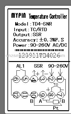
 
The PID runs on 24vdc internally but the built in autosensing power supply needs at least 90v.
Don't take this the wrong way but you might want to do some more reading about how these components work and how they need to be wired... The PID draws less than 1/4 amp.
 
Wait, so all you are doing is trying to use a switch to turn on and off your PID? If so, yes, your SSR idea would work, but you are massively overcomplicating this. Just run the AC current through your switch. PIDs don't generally draw a lot of amperage, so pretty much any well-made switch will be able to handle it just fine.

120V AC hot -> switch -> PID #1 [PID] PID #2 -> 120V AC neutral

Now, if you are worried that your switch is bunk and might short through, say, you, and you would rather run 12V DC for safety and not even touch anything that also touches 120V AC, then you probably shouldn't be using the switch, but yeah, you could do the SSR thing.

But more importantly, why do you even need a switch to turn on and off the PID? If you want a switch to do that, you could use a contactor relay to switch on and off all AC going to the rest of the box.

It's pure aesthetics with the switch. I'm guessing I can't use AC on this switch?
That would really simplify things. I realize this is overly complicated but I'm being petty and really like this switch.

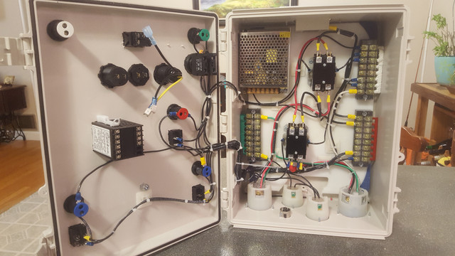
Here's some pics of my panel.

43521.jpg


Also here's a link to my switch. It's a 16 amp switch. If I can run AC through it then this thread is pointless and I apologize. I'm pretty sure I can't and a relay is my only option.

CH4x4 Rocker Switch Beer Symbol - Horizontal - Red LED https://www.amazon.com/dp/B01AAT6UMW/?tag=skimlinks_replacement-20
 
Last edited by a moderator:
Just use any ac rated switch... you can add a 1 amp fuse to the line before the switch to protect the line but yes you want to power the pid with either 120v or 240v either will work. (BTW its not ideal to have the pid on its own switch since you want it to have power as long as the panel is on to be able to see the temp in the kettle even when not heating it. for this reason most power it off of the main power switch)..

Im not sure why you even have all the 12v meter and such going on..(its always going to read 12v BTW since theres no battery) I could be missing it but I dont see any actual application for you 12v power supply in your panel at all? all your outlets at the bottom appear to be AC? Is all that just to have a fancy looking usb charger for your phone or is there another function? I have the same $12 12 utility strip on my golfcart dash.. You could technically use that cheap dc switch to power the pid but it will not light up and it wasnt built or rated for ac power..

And where are your SSR switches? I can see one mounted to the top but I see what looks like 2 element plugs and 2 120v pump plugs? you do realize they make light up ac switches too right? I really hope all that 12v wiring isnt to have light up switches because those are all cheap automotive dc switches? and if you want the switches to light up then why have the indicator light above it? Its very confusing to see illuminated switches being used with indicator lights. You want at least 10a rated AC switches for your pumps.

IM not sure if you know this but the pid has its own power converter inside to supply the correct switching voltage to the SSRs... (thats what the + and - are coming out of the pid. and why they are labeled SSR) did you happen to look at the directions that should have came with the pid? I have used many mypins and I know the directions are in Engrish but they are not that bad really.

Again this is why a better understanding of what your trying to accomplish and how is important BEFORE building the thing.
you can hurt or at the least make a lot of grief for yourself just guessing... Then again im just guessing at what your trying to accomplish by looking at it but it looks redundantly over complicated so...
 
Just use any ac rated switch... you can add a 1 amp fuse to the line before the switch to protect the line but yes you want to power the pid with either 120v or 240v either will work. (BTW its not ideal to have the pid on its own switch since you want it to have power as long as the panel is on to be able to see the temp in the kettle even when not heating it. for this reason most power it off of the main power switch)..

Im not sure why you even have all the 12v meter and such going on..(its always going to read 12v BTW since theres no battery) I could be missing it but I dont see any actual application for you 12v power supply in your panel at all? all your outlets at the bottom appear to be AC? Is all that just to have a fancy looking usb charger for your phone or is there another function? I have the same $12 12 utility strip on my golfcart dash.. You could technically use that cheap dc switch to power the pid but it will not light up and it wasnt built or rated for ac power..

And where are your SSR switches? I can see one mounted to the top but I see what looks like 2 element plugs and 2 120v pump plugs? you do realize they make light up ac switches too right? I really hope all that 12v wiring isnt to have light up switches because those are all cheap automotive dc switches? You want at least 10a rated AC switches for your pumps.

IM not sure if you know this but the pid has its own power converter inside to supply the correct switching voltage to the SSRs... (thats what the + and - are coming out of the pid. and why they are labeled SSR) did you happen to look at the directions that should have came with the pid? I have used many mypins and I know the directions are in Engrish but they are not that bad really.

Again this is why a better understanding of what your trying to accomplish and how is important BEFORE building the thing.
you can hurt or at the least make a lot of grief for yourself just guessing... Then again im just guessing at what your trying to accomplish by looking at it so...

-I've pretty much decided to use a small SSR to power the PID. My girlfriend bought me that switch because of the beer logo on it. I know it's pointless to have a PID switch but it was a thoughtful gift I plan on using.

-The lower center piece is a phone mount for running beersmith/wort apps & digital timer.

-The dc current is for powering the phone charger and a USB powered LED brewery sign that hangs above the panel.

-The DC output is adjustable from 5-24V. Hence the voltmeter. (I know the charging port steps 12v down to 5v)

-I'm powering 1 5500W element. Hence the single SSR. It does receive DC from the PID not the DC inverter. The other large receptacle is for the 240V supply.

-The pump switches are 16 amp.

-My girlfriend's father (master electrician) and I run a full continuity test on the entire panel before plugging it in.

-This isn't my first build but I realize my designs are way different than most on here & I have overly complicated this one.
 
Well that helps because when just looking at it, its very confusing from the pictures. I'm still confused as to why your using indicator lights in conjunction with illuminated switches?

What about getting main contactor with a DC 12v coil and use that to enable the switch to be used to turn the whole panel on.
Or better yet wire it to control the element output contactor so you can still use and adjust the pid settings without having the element firing when you dont want it to? I have a switch for this myself on all my pids. then again maybe thats what the red illuminated switch and light are for?

Alternative solution: fake switch that does nothing except light up.
 
I really like the 12v coil on the main contactor idea. If I order more parts that's what I'll do. Dummy switch solves all problems and is super simple. For now that's what I'll do. Thanks guys!

Cheers
 
Back
Top