Quick electrical question about transformers

Homebrew Talk - Beer, Wine, Mead, & Cider Brewing Discussion Forum

Help Support Homebrew Talk - Beer, Wine, Mead, & Cider Brewing Discussion Forum:

This site may earn a commission from merchant affiliate links, including eBay, Amazon, and others.

blackheart

Well-Known Member
Joined
May 4, 2008
Messages
315
Reaction score
19
Location
Binghamton, NY
Hi. Making some progress with our build. Ran into a question. We have a 120 -> 24v AC transformer

The inputs have your standard 3 wire AC connections.

The outputs also have 3 outputs, one labeled 12v, one 24v..... Do I use the 24v one or bridge them together or what?

I'm thinking it could be like 220v... where their are 2 hot 120v lines, maybe the transformer makes two hot 12v lines... or maybe it just does both 12 and 24 volts...

Any ideas?
 
what's the third output wire say? if you want 24 v, you're probably going to grab the 3rd output and the one marked 24v
 
First of all, what are you trying to do with it? Are you wanting 24vdc or 12vdc? Many transformers come with two or more output voltages, I imagine yours is similar. I just saw one at Fry's that has 120vac input and 12vcd & 24 vcd output. Do you have three pairs of output wires or just three wires? If you have three wires, I imagine one is the ground, the other two are the voltages labeled. So if you want 24vdc then you use the 24vdc and the ground wire...
 
The wires are | Com | 12 | 24 |

Using this to power gas furnace valves.

I guess I will just try the 24v hookup then with the multimeter. Just wanted to ask now so I did not run into a surprise later when I attempted this.
 
To give you a better understanding of how household voltages and transformers work I'll see if I can explain this to you.


In the house, the hot of a 120 system comes off the top of the transformer coil that converts 3 phase 70Kv to 2 phase 220. The neutral comes from the MIDDLE of the transformer coil, and the other 120 comes off the BOTTOM.

Sense AC is in a sin wave, as the voltage wave form travels across the transformer coil the middle of the coil is always at the 0 point of the sin wave. The ends of the coil are at the peaks of the sin wave. This means that one end of the coil has +169v from the center tap, and the other has -169v from the center tap (AC is measured in RMS (root mean square) which for a standard sin wave means that the peak voltages are root(2)*RMS voltage). Thus, when you tie completely across the transformer coil you get 120 - (-120) = +240 VAC. But if you wire to the center you get either one phase of 120 (posative) or 180 degrees out of phase (-120).

When your 120 VAC transformer is wired up you're using 1 of the house phases. The center tap is usually grounded to prevent DC offsets. A transformer can only transfer AC voltages due to -dV/dt effect of magnetic fields. Thus its possible to get 24 VAC out from the transformer, but to have the "0" point of the sin wave be at 10,000 volts if the circuit got static charged, this is why you have that center tap input, to make sure the DC voltage of the primary coil is lined up to earth ground (even though neutral is tied to earth ground at the breaker box, because the neutral is carrying current it might have a higher voltage than earth ground at your point of contact, this is one of the reasons you always run ground with a neutral).

Thus the output of your transformer is giving you the center tap, top, and bottom of your coil. From COM to 24 is most likely top to bottom, COM to 12 is most likely bottom to middle, and 12 to 24 would most likely give you 12 VAC 180 degrees out of phase with COM to 12.

Does that make sense?
 
Excellent explanation. Makes sense to me now. I am wiring up 120AC/24AC/12DC/5DC all in the same box to control various devices. All the 120AC stuff is getting grounded. Wiring up a standard outlet for the pumps to plug into.

Would a standard DC barrel connector found on most DC transformers work for 24v AC connection? Is their a better connector to use? I need two.

I am confused by what you mean "dc barrel connector" and DC transformer (the term in its self is an oxymoron, do you mean the AC to DC converter or a DC to DC converter?) Are you talking about the crimp connectors that many people use to do their connections when you say "barrel connector"?
 
I mean the one that looks like a tube. With an ID and OD. Most DC devices connect to a AC/DC transformer this way.
 
I mean the one that looks like a tube. With an ID and OD. Most DC devices connect to a AC/DC transformer this way.

Do you mean the connectors that usually come on things like wall worts?

like this?
http://en.wikipedia.org/wiki/Coaxial_DC_Power_Connectors

If so, yes that will work for 24 VAC, as long as its big enough, also depends on the current you're running. If you're pulling 20 amps at 24 VAC, then no they wont really work.

I'd suggest the EIAJ-05 size, in small sizes at higher voltages you may arc from the hot to the neutral.
 
Thats the one. I am using a "M" size connector for 12vDC thats rated at 2A for the 1-1.5A 12vDC valves. Its 5.5 OD.

I am guessing if the amperage is around 1-5A I can use a similar large connector. Any other connector types you would recommend besides that?
 
The difference between the ID and the OD is what is important, you need a larger difference between them to reduce arcing at higher voltages, 24VAC is pretty low, but it's just to make sure.

If its rated for 2A I wouldnt put 5A through it.

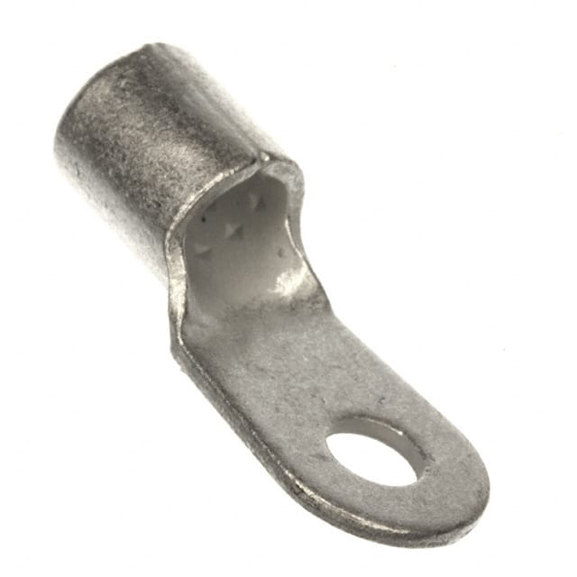
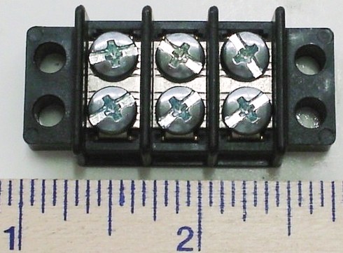
If I was doing the project, and I'm not sure how you're exactly wiring this thing, I'd wire the 120 - 24 transformer to a screw panel bus, and then wire my switches/relays from that to another bus that then connects to the solenoids, and use these connectors:

19193-0245.JPG


then solder them rather than just crimp them.

screw bus for the AC:
Buss_Bar_1.jpg


and something like this for the output of the relays to the devices:
13-1403B.jpg
 
ok, now I'm understanding your question better.

In that case I would use these guys:

IEC60309-2.jpg


it's a mini IEC 60309

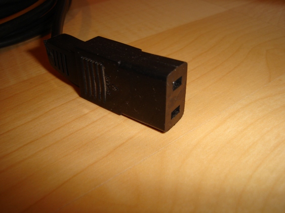
IEC C9 and C10 would also work well
C9IECConnector.JPG


mostly because if you're going to run 5 amps, you need something more.
 
Those are some cool looking connectors... but I only need 2 pins and 2 connectors total... again I'm not sure of the Amperage offhand but it cant be that much. That looks like a bit to specialized connector to me... like special order and $$$ type of connector.
 
Yea I'd check your amperage and then decide. The barrel connectors will work as long as you have a good ID to OD difference, and are using under 2A.
 
I'm going to wire things strait up tonight to test so I should know by tonight. Considering the valve has spade terminals on it the amperage cant be too crazy. Then again I dont want to rebuild this because the plugs are melting.... Thanks for the info. I will let you know how it turns out.
 
Back
Top