Open ArdBir Nano eBIAB Build

Homebrew Talk - Beer, Wine, Mead, & Cider Brewing Discussion Forum

Help Support Homebrew Talk - Beer, Wine, Mead, & Cider Brewing Discussion Forum:

This site may earn a commission from merchant affiliate links, including eBay, Amazon, and others.

schiersteinbrewing

Supporting Member
HBT Supporter
Joined
Mar 25, 2013
Messages
619
Reaction score
140
Location
Stanton
Not long ago I built a BrauSupply Clone system. I am going to convert it into an automated system using Open ArbBir and a Arduino Nano.

BrauSupply Clone w/12v pump

https://www.homebrewtalk.com/attachment.php?attachmentid=375665&stc=1&d=1478032600

https://www.homebrewtalk.com/attachment.php?attachmentid=375666&stc=1&d=1478032600

Thus far I have sourced and ordered all the components (I think).

10k Ohm Resistors
1k Ohm Resistors
470 Ohm Resistors
IN4007 Diodes
BC337 Transistors
IRFZ44 Rectifiers
3362P-1-103LF 10k Potentiometer
B008MU206C 12v Relay
DS18B20 Probe and Sensor
2 Pin Plug-in Screw Terminal Block
3 Pin Plug-in Screw Terminal Block
40Pin 2.54mm Single Row Straight Male Pin Header Strip
Copper Clad PCB
PCB Mount Mini Speaker - 8 Ohm 0.2W
20X4 Character LCD Module Display For Arduino
Arduino Nano V3.0 ATmega328
Assorted 3mm/5mm LEDS
Momentary Push Button Switches
Circuit Board Thermal Transfer Paper
Ferric Chloride

My sources have been:
https://www.homebrewtalk.com/showthread.php?t=540002&page=1
https://github.com/ArdBir
https://github.com/arzaman

I have worked on the PCB design as I couldn't figure out how to use the design in the Github to work with the toner transfer method. The main source for toner transfer methods was using the Arduino Uno. After extensive searching found this page http://www.piwo.org/topic/10829-sterownik-do-kadzi-zaciernej/page-4

It had this PCB design I could work with.
https://www.homebrewtalk.com/attachment.php?attachmentid=375672&stc=1&d=1478034120

After a few hours of PhotoShop, scanning, and a Sharpie Pen I ended up with a final PCB design.
https://www.homebrewtalk.com/attachment.php?attachmentid=375673&stc=1&d=1478034201

Getting the correct sizing on the print out for the PCB is my next hurdle.

Now I wait on components to trickle in.

Update:
Found a list of components for the build.

01 Arduino Nano
01 LCD 20x4 Blue background and White letters
01 mini size relay for 12V (not needed if used a SSR for pump)
01 Buzzer 12V

R8 - 120 Ohms
R2, R10, R11, R14, R15 - 1K Ohms
R1 - 2k7 Ohms
R4, R5, R6, R7 - 10k Omhs
R3, R9, R12, R13, R16 - 1M Ohms
P1 - 10k Ohms

D1, D2, D3 - 1N4007
Q1, Q2 - BC337
Q3, Q4 - IRFZ44N

08 Two Way PCB Mount Screw Terminals
02 Three Way PCB Mount Screw Terminals
01 Strip Line Connector Single Row Straight Terminals(come with 40 pins)
01 PCB sigle 11cm X 9cm

4 push-buttons as keypad

2016-02-01 17.43.47.jpg


2016-02-01 17.47.14.jpg


ardbirnano.jpg


sbcnanosign.jpg
 
I realized in tinkering with the "prototype" that my resistor to the display was to large and causing the display to be to dark. I miss read the specs and used a 470k ohm resistor instead of a 470 ohm. That's why it's on bread board first.
 
Super cool. I used strangebrew and a pi. Love the automation


I already have an automated 16g Brew Boss system, which is awesome. I am a tech person and love learning; so in turn I tinker, challenge 1 build a PID system (done), challenge 2 build a Arduino system, heck by this time next year I'll have a PI system or use PI to control my Ferm chamber.

In high school (20yrs ago) I was very good at coding (c++). In college I set out to be a Computer Sci major(Chemistry was my weak link), just finally graduated with a business degree to get out. I wrote some sweet programs in college some of which the University used. My mom got sick with cancer and I taught her Comp Sci classes during in that time, teaching high school Java. It's been 10yrs and and coding has changed 10 fold since my days. I am enjoying coding again and plus learning. I see life as a challenge and everything as a learning opportunity.
 
My PCB arrived today here is what I was able to get done.

Cut out of a larger 12x12 piece using my tile saw. Roughed up surface with a green scrubbing pad and cleaned with acetone.

View attachment ImageUploadedByHome Brew1478659156.544379.jpg

Bought PCB transfer paper to do the job. As a side note, don't use scotch tape to hold the paper down. It melts and makes a mess on your iron.

View attachment ImageUploadedByHome Brew1478659254.229386.jpg

All in all did pretty good, touched up areas with a marker before the etching.

View attachment ImageUploadedByHome Brew1478659351.027662.jpg

Here we go. Side note don't use a good polished stainless steel fork for this, it is no longer polished.

View attachment ImageUploadedByHome Brew1478659413.125706.jpg

Not to shabby, the areas where the scotch tape melted didn't get etched.

View attachment ImageUploadedByHome Brew1478659523.764984.jpg


Scrubbing off the black stuff was not fun.

View attachment ImageUploadedByHome Brew1478659585.305827.jpg


Holes drilled and ready for soldering.

View attachment ImageUploadedByHome Brew1478659622.497835.jpg
 
So decided to stay up and watch the election last night. While listening to the TV I soldered everything to the board.

That was a learning experience, I have done some soldering here and there nothing like this. Here is what I learned.

1. soldering iron was to hot
2. used the wrong tip in the iron (screw driver style was all I had)
3. the copper pops off if you get to it to hot or if you stick your solder wire to it and yank back when you realize what you've done
4. Things are very close together ( also falls under wrong tip)
5. Use female header strips for Nano and LCD instead of soldering them to the board
6. Test things as you go
7. Have a spare Nano on hand

So after hours of listening to the TV and trying to figure out what goes where, how this needs to be oriented to work, tired hands, burnt fingertips the moment of truth arrives; plug the nano and attached circuit board in to my laptop it powers up LCD comes on, open the Arduino software, upload the program, during the upload you hear fizz, pop and see/smell smoke. Quickly yank the USB cable from the computer and say a few choice words to yourself (wife, baby, and teenager are sleeping). This is where numbers 5,6,7 from above come in to the picture. Go get the solder wick from the garage and start getting the Nano off, destroy the fragile copper circuitry in the process. So after getting the Nano off start removing the LCD. Look at the Nano and a diode on the bottom is toast. Thankfully my laptop is safe and unharmed.

So today I have spent many hours looking at the PCB and schematic trying to figure out where I went wrong. Also with more hours on the internet trying to find PCB designs. The hours of internet research did yield a single Dropbox account gold mine of PCBs, manuals, old/new version on ArdBir. I downloaded everything just in case it disappears. I have ordered a replacement Nano, temporarily fixed my current Nano, got the program loaded on the Nano (that's the last time it will be connected to my laptop) , tested the LCD on breadboard ( it's okay), and ordered female header strips.

I think the issue is I didn't get the direction correct on the IRZ44 (s), BC337(s), or didn't use enough resistance some where

The gold mine of PCBs, Manuals, Libraries and Versions:
https://www.dropbox.com/sh/igkch19thwd64ey/AABxEf0zEHHt2Qopm7DZVu6Ca?dl=0
 
I feel you man. It is painful when you put the energy into a good DIY project only to find it go south and all your time and energy "wasted". I quote the wasted, because you learned something in the process, but are not that much closer to your goal.

Personally I think having a board made rather than etching your own makes economic sense these days, as you can get one-off boards cheap enough.
 
Yeah, it could be that the nano won't call for heat unless the setpoint is higher then the temperature reading. If there is no probe hooked up it will not call for heat as it reads like 40000 degrees.
 
I was going to make that board but the Chinese Arduino I had was a slightly different pinout so I ended up going with the uno version. Maybe send a pic of your shield and maybe someone can spot the error.
 
Yeah, it could be that the nano won't call for heat unless the setpoint is higher then the temperature reading. If there is no probe hooked up it will not call for heat as it reads like 40000 degrees.


I used the original board I printed and reversed the heater diode. Then just used my uno and held the wires to the circuits it works. So I don't have something right on bread board.
 
Dude that's awesome. Is the board you modified for the Chinese nano the one you posted on the main post? I would love to have a copy
 
dude, you are amazing.
I like DIY too, but I could never do something like that. I have only skill of programming.
A year ago, I started to develop my own controller by studying Open ArdBir. Now, I get something like this.
DIY to me is that I can do anything I want if I could. It's nothing about money or time.

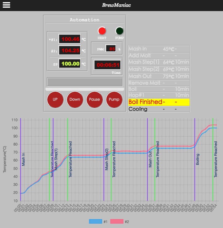
screenshot.jpg
 
The female strips came in today and I was able to get them soldered up.

View attachment ImageUploadedByHome Brew1479523825.419344.jpg
View attachment ImageUploadedByHome Brew1479523840.562841.jpg
View attachment ImageUploadedByHome Brew1479523857.970945.jpg

More pics to follow tonight after the fam goes to bed and I can do more work.

View attachment ImageUploadedByHome Brew1479527629.590175.jpg

Pump and heater are firing (red LED pump/ green LED heater).

Side note I did have to remove and rotate 180deg the two transistors that are on the left that control the pump and spare. I originally had them backwards.
 
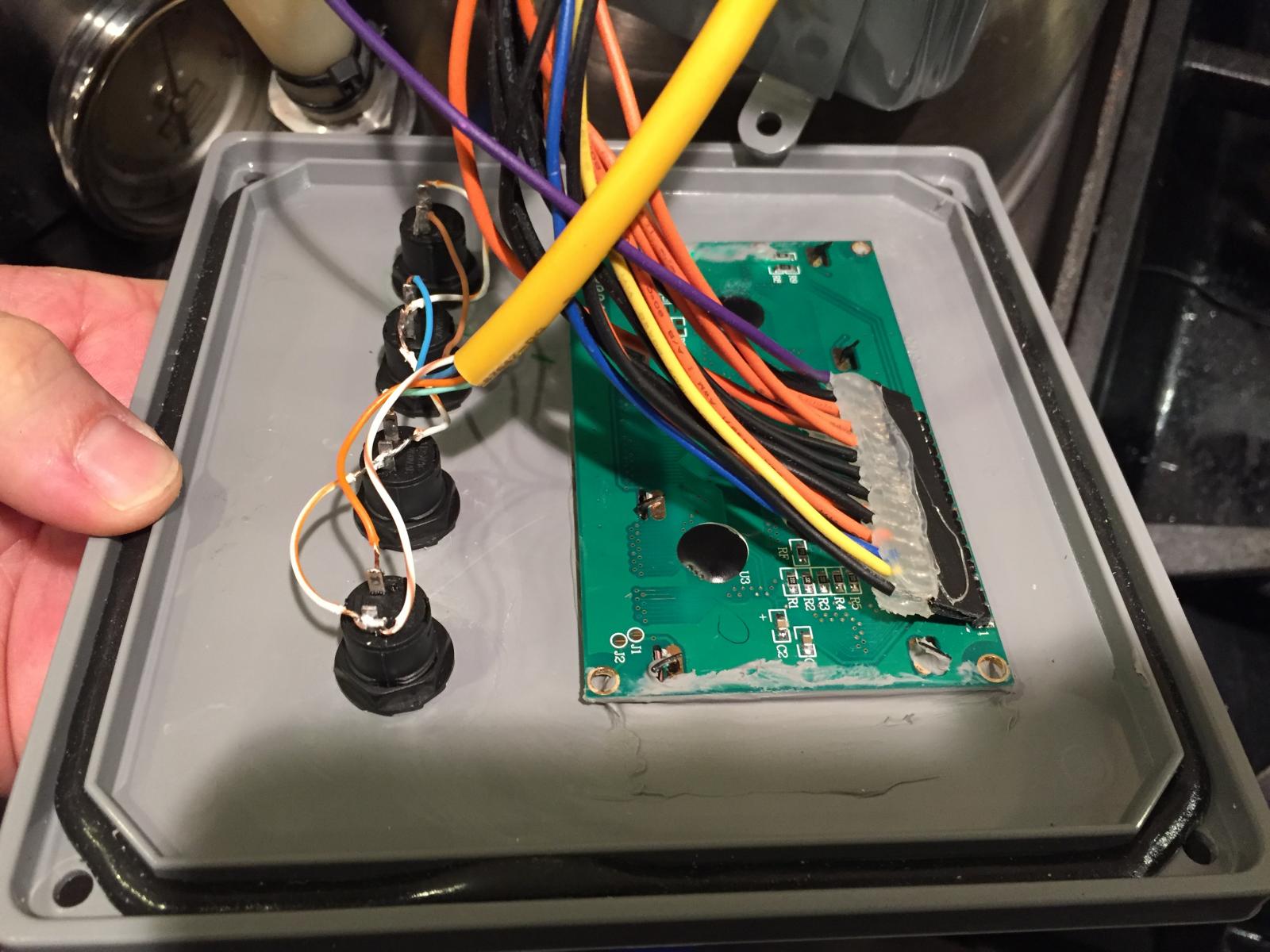
For it to all fit in this small of a box I had to make a "ribbon" cable for the display.

Not quite 100% complete but it's close. Done enough I can make some test runs. Need a longer temp probe wire and an easy way to remove/connect temp probe; I'm thinking a stereo headphone jack similar to how the Brew-boss is done. Need a thermo well for the temp probe. Also need a way to remove/connect pump. Open parts will be sealed with grey silicone caulk.

View attachment ImageUploadedByHome Brew1479767575.063626.jpg
View attachment ImageUploadedByHome Brew1479767592.663067.jpg
View attachment ImageUploadedByHome Brew1479767758.340664.jpg
 
Ordered a 2meter temp probe and a microphone connection for it.

Wet run went well. Trying to dial in the PID settings.
Okay but overshot
P - 50
I - 1
D - 10

Fast but way over shot
P - 100
I - 20
D - 5

I found a way to tune it but need to set the duty cycle how do you do that?
 
Nice work!following you!
am planning to build the same CC, I've ordered most of the components :ban:
 
I ended up leaving my PID settings on whatever was there. When I did a wet run test it was overshooting, but when the whole volume of water was in there it was dead on so I just left it.
 
I ended up leaving my PID settings on whatever was there. When I did a wet run test it was overshooting, but when the whole volume of water was in there it was dead on so I just left it.

My wet run was full volume (8 gal). Thanks, I will reload the program and go with defaults and see what happens.
 
Yes that is the one i have exactly, but after further investigation i realize now that is the Arduino mini. There is no board that fits the chinese mini but it probably wouldn't take too much to modify the board

Yeah I miss read the eBay title and description, so I ended up with 5 of the Arduino Mini's.
 
To get the buzzer to work I gave up on the original placement. I ended up just using the spare pump (D8 on the Nano) by changing the "board".h file. As soon as I did that the buzzer worked.

Note: In the picture the buzzer is still located in its original position, it has since been moved. I have also ordered a louder buzzer.

2016-11-22 21.54.21.jpg


2016-11-22 21.54.32.jpg
 
Cost was approximately $160 with out reusing any parts from my PID controller. Now including cutting wheels for my Dremel, caulk, ferric chloride, and the various screw ups I made when ordering parts and frying two Nanos the cost was approximately $240.
 
Borrowed a lab grade thermometer and logger from our chemistry teacher where I work.

I calibrated both the Ardbir and the lab termo in ice water. What I am noticing is that the temp out put by the Ardbir gets further away from actual as the temperature increases. Has anyone noticed this?

Double checked with my Thermapen and a calibrated dial thermo. At one point I was using 5 thermometers.
 
I assume using 1-wire sensors? They should be accurate to within a degree. You only really care about accuracy at mash temp anyway. Calibrate there and ignore freezing and boiling temps. Does the software have any calibration mechanisms (offset/slope/etc.)?
 
I assume using 1-wire sensors? They should be accurate to within a degree. You only really care about accuracy at mash temp anyway. Calibrate there and ignore freezing and boiling temps. Does the software have any calibration mechanisms (offset/slope/etc.)?

Yes its a one wire and yes I have the temp correction maxed out. If I cant figure it out thats my plan just calibrate at mash temp and call it good enough.


Also having issues with the Fahrenheit settings, it isn't pulling the def F settings it just uses Celsius settings.

I'm using v 2.8.3, may try older versions and see what happens.

I've got time to play with it, all my fermenters are full and all my kegs are full.
 
Back
Top