You are using an out of date browser. It may not display this or other websites correctly.
You should upgrade or use an alternative browser.
You should upgrade or use an alternative browser.
My new brew system, a brutus 10 with some nice modifications

Help Support Homebrew Talk - Beer, Wine, Mead, & Cider Brewing Discussion Forum:
This site may earn a commission from merchant affiliate
links, including eBay, Amazon, and others.
OneHoppyGuy
Well-Known Member
joelireland
Active Member
Hmmmm ... conflicting opinions - love it.
I will have a fair bit of length spare so I might give it a crack by hand and see how she goes. I guess I will need a bender for my pick up tubes in any case.
Once I get my tubing I will let you know if I have any problems.
I will have a fair bit of length spare so I might give it a crack by hand and see how she goes. I guess I will need a bender for my pick up tubes in any case.
Once I get my tubing I will let you know if I have any problems.
2NobleDogs
Well-Known Member
I have the same panel box connectors for my RTD sensors. Anybody know the proper way to make the wire connections to the connector posts? 
OneHoppyGuy
Well-Known Member
2Noble... your post comes somewhere out of left field. Can you put a link to the particular post (click the number to the left of the post and paste the address) or give us a photo
2NobleDogs
Well-Known Member
I guess that was kinda out of the blue. Here is a link to the connectors I'm referring to: Panel mount connector for RTD sensor [RTDCON] - $3.75 : auberins.com, Temperature control solutions for home and industry
You can see them in action on post #10. I'm using them to connect the STD sensor to the panel box. The problem I am having (being a dolt at this type of thing) is making the wire connection to the posts. Because the posts are straight (w/o holes) there is no way to hook or solder the wire to it. I'm sure there has to be a tiny wire connector that just slides onto it but I cannot find anything. Sorry I don't have a picture of the actual post.
You can see them in action on post #10. I'm using them to connect the STD sensor to the panel box. The problem I am having (being a dolt at this type of thing) is making the wire connection to the posts. Because the posts are straight (w/o holes) there is no way to hook or solder the wire to it. I'm sure there has to be a tiny wire connector that just slides onto it but I cannot find anything. Sorry I don't have a picture of the actual post.
Cant you heat the post a bit, apply some solder, then reheat the solder and place the wire. Another thought that comes to mind is the slip on mounts. Post a question here, Durham Mountain Brewery | Facebook
You may get a response.
You may get a response.
OneHoppyGuy
Well-Known Member
The longer piece disassembles
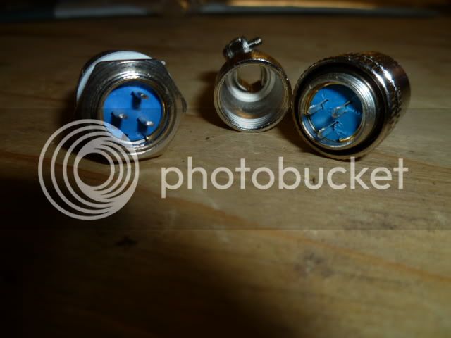
I have placed a wire on one of the posts to show where you should solder.
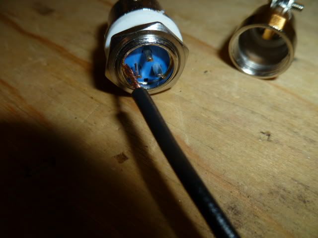
Note the the posts are cupped to hold the solder and wire.
You will want to use a small soldering iron to avoid getting the posts too hot and melting the plastic. You will have to tin the wire and the post before attempting to solder them together.
Remember when you are soldering to reverse the wires on one of the disconnect sides so they match when they're attached. Wiring configuration doesn't mater on the posts as long as the PID has the correct wiring.
Reading glasses, a magnifying light and a miniature vise come in handy for this project.
I have placed a wire on one of the posts to show where you should solder.
Note the the posts are cupped to hold the solder and wire.
You will want to use a small soldering iron to avoid getting the posts too hot and melting the plastic. You will have to tin the wire and the post before attempting to solder them together.
Remember when you are soldering to reverse the wires on one of the disconnect sides so they match when they're attached. Wiring configuration doesn't mater on the posts as long as the PID has the correct wiring.
Reading glasses, a magnifying light and a miniature vise come in handy for this project.
drkwoods
Well-Known Member

CollinsBrew
Well-Known Member
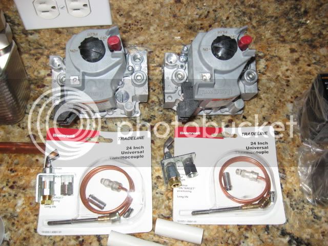
Finally back in the states and have all of the parts. By the new year I'll have a finished stand and control box.
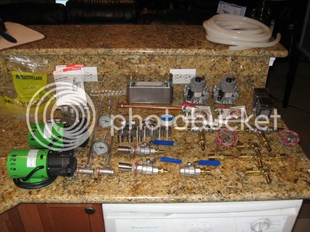
The temperature probe.
Auber Temp Controllers
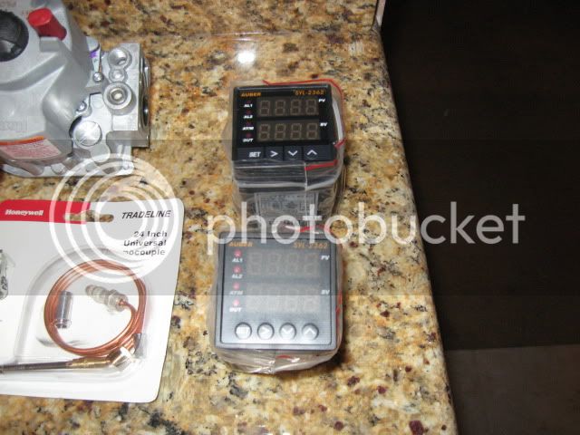
Propane Valves and Pilot lights
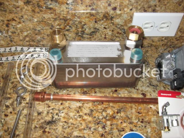
Dudadiesel 30-plate chiller
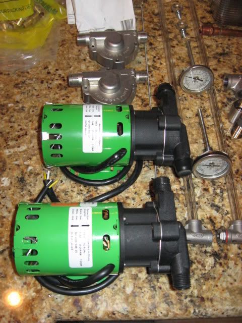
Original Chuggers with Stainless Heads and Sightglasses
The temperature probe.
Auber Temp Controllers
Propane Valves and Pilot lights
Dudadiesel 30-plate chiller
Original Chuggers with Stainless Heads and Sightglasses
CollinsBrew
Well-Known Member
Picked up some of my electrical components today. I got a few from a friend and then stopped by radio shack to grab some of the stuff he didn't have. They had Radio Shack brand transformers (part # 273-1512) there so I picked one up but may need to take it back. It's rated with both yellow wires to be 25.2V 2A.
The door chime transformers at Home Depot are rated for exactly 24V 20VA and are probably a better fit for what I need.
Also, I'm going to buy the wire for this tomorrow and need to was curious what gauge you guys went with? An earlier post mentioned 12 which I guess I could use for everything but seems like a bit of overkill for the 24V stuff. Any input?
drkwoods
Well-Known Member
Ive seen several threads on Banjo distance to the Keggle, but it seems most are regarding high pressure LP. Does anyone know the suggested distance if you are using Low pressure LP (i.e. 11"wc) ? I put mine at 4" but it seems far... ideas??
Zeek
Well-Known Member
- Joined
- Nov 29, 2008
- Messages
- 49
- Reaction score
- 1
There seems to be alot of people that are using the 10" banjo burners on low pressure, but not much info appears to have been posted about the best distance from the bottom of a keggle! I am interested to find out also.:rockin:
CollinsBrew
Well-Known Member
Still no advice on the wire gauge to use?
drkwoods
Well-Known Member
Spoke with Derrin @ Brewers Hardware, LLC. and his recommendation is is 2" of distance from a Banjo running low pressure LP (11" w/c) to the Vessel Bottom. Im going to try this tomorrow and report back
Huaco
Well-Known Member
Wow... have read the entire 30 page thread! Inspiring... I think my tax refund for next year is already allocated! haha!
drkwoods
Well-Known Member
I lost 50% of my eyesight reading and re-reading this!! LMAO. But I expect to gain it all back when I start my own Brewery Build Thread in a week or two here! Look for it..Huaco
Well-Known Member
Did this in the hour after work... Its a start.

2NobleDogs
Well-Known Member
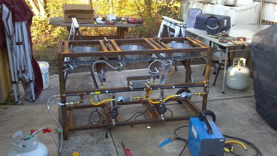
Here is my build so far. I'm still working out some controller issues but will hopefully be brewing by the weekend. BTW- I am planning on cleaning it up and painting it Many thanks to everybody who has posted on this thread...especially Josh! His build has been quite the inspiration
 .
.
Cheers!
Many thanks to everybody who has posted on this thread...especially Josh! His build has been quite the inspiration
Cheers!
Huaco
Well-Known Member
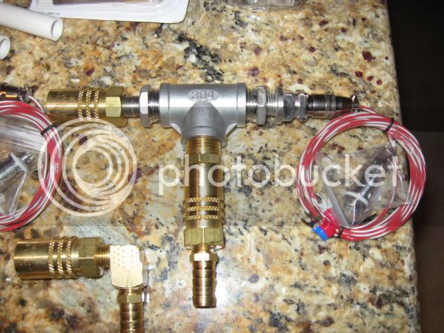
Why the need for a regulator at the tank as well as the additional 2 regulators at the controlled gas valves?
Huaco said:Why the need for a regulator at the tank as well as the additional 2 regulators at the controlled gas valves?
I was wondering the same thing
OneHoppyGuy
Well-Known Member
Why the need for a regulator at the tank as well as the additional 2 regulators at the controlled gas valves?
Furnace gas valves will not work above 3 psi. If you used a low pressure regulator at the tank, the boil kettle would take much longer to come up to boiling point due to the reduced BTUs.
2NobleDogs
Well-Known Member
furnace gas valves will not work above 3 psi. If you used a low pressure regulator at the tank, the boil kettle would take much longer to come up to boiling point due to the reduced btus.
+1
CollinsBrew
Well-Known Member
If you're using low pressure LP with low pressure burners then your btu loss shouldn't be that significant. High pressure has a smaller gas orifice requiring a higher pressure to push through he same amount of gas. A larger orifice allows more gas through and a lower pressure. Essentially, you're using a similar amount of gas and creating a similar amount of btu's. Notice I'm not saying the same amount, but the loss I don't think, will cause will cause your boil times to be that different. Maybe in much higher liquid volumes this could be the case.
Then again, like was previously suggested, you could run your two furnace valves on low pressure and your boil kettle on a high pressure regulator if you're that concerned. I'm planning on having one low pressure regulator right off of the tank and running them all that way.
Then again, like was previously suggested, you could run your two furnace valves on low pressure and your boil kettle on a high pressure regulator if you're that concerned. I'm planning on having one low pressure regulator right off of the tank and running them all that way.
I am building single tier 3 burner system with 10" banjos. I've tested boil times using high pressure propane and low pressure propane feeds (via Honeywell gas control) to the burners. I can definitely say the low pressure burners take about 40% longer to boil 20 gals of water compared to the high pressure fed burners. I have the correct orifices installed depending on the pressure and have tweaked the air / gas mixture in every conceivible combinations but the low pressure just does not compete or burn as clean as the high pressure fed burner. I don't know why, perhaps it's the banjos are designed for high pressure in mind?
Anyway I'm going with low pressure to the HLT and MT, with high pressure on BK so I can get a quick and rolling boil going. I don't need burner temp control on BK so don't need the Honeywell gas control there
Anyway I'm going with low pressure to the HLT and MT, with high pressure on BK so I can get a quick and rolling boil going. I don't need burner temp control on BK so don't need the Honeywell gas control there
Zeek
Well-Known Member
- Joined
- Nov 29, 2008
- Messages
- 49
- Reaction score
- 1
Spoke with Derrin @ Brewers Hardware, LLC. and his recommendation is is 2" of distance from a Banjo running low pressure LP (11" w/c) to the Vessel Bottom. Im going to try this tomorrow and report back
Did you get a chance to try this? If so, how did it work out?
Thanks
Zeek
drkwoods
Well-Known Member
I will test the 2" distance next week n report back
drkwoods
Well-Known Member
The 2" distance doesnt work well. I was given bad advice I think, at least for my system. The flames wanna come up the kettle sides 10". Thats 10" too much for me.. One of the burners actually is getting "balls" of flame under the burner as there is too much unburned gas dropping belwo the burner and igniting.. I lifted the kettles up 2" and they performed perfect. So Im going back to mounting my Banjo burners 3-4" from the Bottom of the Keggles..
Did this in the hour after work... Its a start.
What 3D program are you using? Just curious, I use Solidworks myself.
rtockst
Well-Known Member
The jlandin removable control panel is money.
I built a panel just like it, and I've got a very strange voltage reading. I was checking the 24v lead to the honeywell valve, and it measured 62 volts! It did that with both valves . I checked the transformer output, and it was 27, which is fine. What's causing it?
I built a panel just like it, and I've got a very strange voltage reading. I was checking the 24v lead to the honeywell valve, and it measured 62 volts! It did that with both valves . I checked the transformer output, and it was 27, which is fine. What's causing it?
OP
OP
jlandin
Well-Known Member
The jlandin removable control panel is money.
I built a panel just like it, and I've got a very strange voltage reading. I was checking the 24v lead to the honeywell valve, and it measured 62 volts! It did that with both valves . I checked the transformer output, and it was 27, which is fine. What's causing it?
Are you running the 24V source through the PID? If you have the SYL2362 PID, check the manual (here) section 10.3 and make sure your wiring is correct.
rtockst
Well-Known Member
jlandin said:Are you running the 24V source through the PID? If you have the SYL2362 PID, check the manual (here) section 10.3 and make sure your wiring is correct.
Yes, I'm sending the 24v line to an hoa switch, then to the 13 pin. The 14 pin is going to the coaxial panel mount. The neutral on the panel mount is going to the neutral bus.
OP
OP
jlandin
Well-Known Member
Yes, I'm sending the 24v line to an hoa switch, then to the 13 pin. The 14 pin is going to the coaxial panel mount. The neutral on the panel mount is going to the neutral bus.
You'll have to use your multimeter to test the circuit at each point. Test the voltage at the 24V output (pre-switch), post-switch into PID, PID output (directly), and the coaxial output connector. Also check the voltages when you have your switch in "Manual/On" mode.
rtockst
Well-Known Member
You'll have to use your multimeter to test the circuit at each point. Test the voltage at the 24V output (pre-switch), post-switch into PID, PID output (directly), and the coaxial output connector. Also check the voltages when you have your switch in "Manual/On" mode.
The manual/on mode reads 62V also. Preswitch it's 27V. PID output is 62V. I didn't check the post-switch into the PID. I'll do that when I get home.
Do you think it could be the switch? I'm not using a SPDT. I picked up the wrong one, and it's a DPDT. I'm only using 3 of the 6 pins though. The auto/off/manual functions work, but do you think it could possibly be changing my voltage? That's the only thing I can think of.
OP
OP
jlandin
Well-Known Member
The manual/on mode reads 62V also. Preswitch it's 27V. PID output is 62V. I didn't check the post-switch into the PID. I'll do that when I get home.
Do you think it could be the switch? I'm not using a SPDT. I picked up the wrong one, and it's a DPDT. I'm only using 3 of the 6 pins though. The auto/off/manual functions work, but do you think it could possibly be changing my voltage? That's the only thing I can think of.
Yepper... you have the switch wired wrong. Just go down to Radioshack and throw down the $3 for a SPDT.
Similar threads
- Replies
- 0
- Views
- 279
- Replies
- 4
- Views
- 565
- Replies
- 3
- Views
- 1K
- Replies
- 10
- Views
- 638
