List of PJ Electrical Diagrams

Homebrew Talk - Beer, Wine, Mead, & Cider Brewing Discussion Forum

Help Support Homebrew Talk - Beer, Wine, Mead, & Cider Brewing Discussion Forum:

This site may earn a commission from merchant affiliate links, including eBay, Amazon, and others.
Does anyone know of some circuit diagrams that use STC1000's and electromechanical relays? I'm on a super-tight budget, don't need a lot of whistles, bells, and buzzers, and have some of the parts already.
my STCs are 220v.
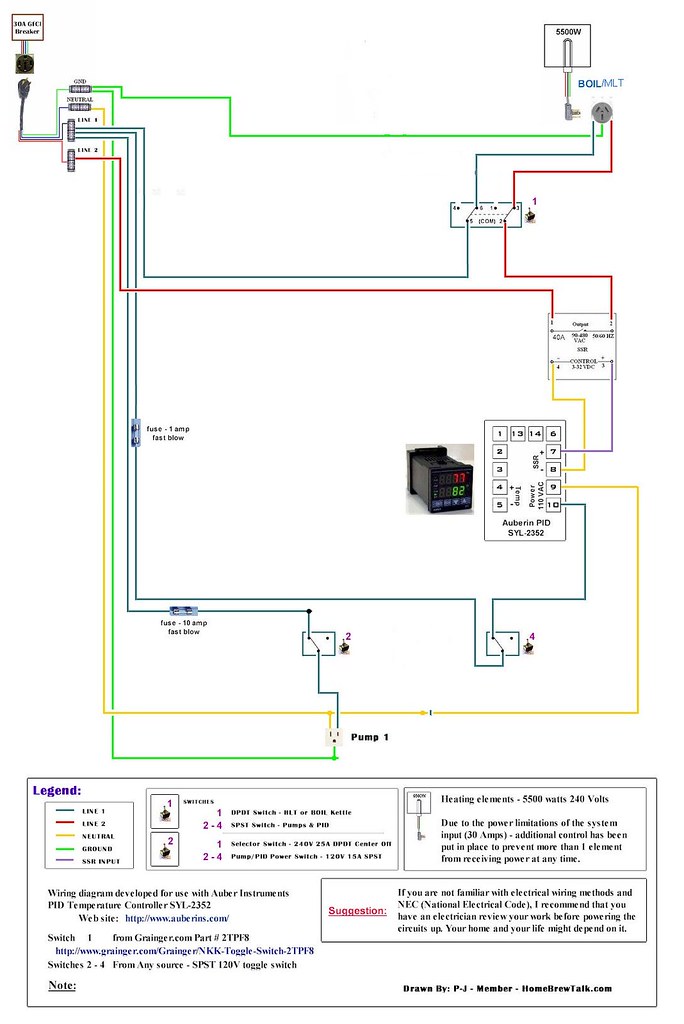
I'm just looking for some diagrams to give me ideas so I can use/butcher/modify them for my own use. I'm presently using some from PJs collection, and have done some extensive white-out work to make them close to what I want.
Maybe if I had a small diagram of how an electromechanical relay is wired into the system between the 240v output of the STC and the 4500W element, that would suffice. I think I've got everything else just the way I want it.
TIA
 
If I understand the question:

Line1 --->HtrA--->HtrB--->ContactorA---->ContactorB---->Line2

Line1---->STC1000A----->STC100B---->ContactorCoilA----->ContactorCoilB---->Line2

Hope that's clear.
 
If I understand the question:

Line1 --->HtrA--->HtrB--->ContactorA---->ContactorB---->Line2

Line1---->STC1000A----->STC100B---->ContactorCoilA----->ContactorCoilB---->Line2

Hope that's clear.
Nope, didn't help me a bit (I know, I'm a dummy!) -
The way I understand contactors and relays is; IF I run a 12v line to the coil, that actuates the relay (NO to NC). IF I run 240v (L1 & L2) to one side of the relay and run the corresponding wires to the heating element (L1 & L2) on the other side of the relay, when the coil is actuated by applying 12v, the contacts in the relay go from NO to NC, so I will then have 240v power going across the relay to the elements. This is how I understand them to work - is this what you meant by the above explanation?
TIA
 
I just have two questions:

1. Would it be possible to replace the glass bulb fuses with automotive blade fuses?

2. Can the 1 amp fuses in the first diagram listed be safely replaced with 2 amp fuses?
 
I just have two questions:

1. Would it be possible to replace the glass bulb fuses with automotive blade fuses?

2. Can the 1 amp fuses in the first diagram listed be safely replaced with 2 amp fuses?
Most automotive blade fuses are rated for 32V or 58V (I didn't find any higher ratings on a very short search), so these should not be used in 120V or 240V applications. What's the attraction of using those vs. the cylindrical glass fuses?

For the second question, I'm going to give a snarky answer: If you don't know how to determine acceptable fuse ratings, you shouldn't be considering altering the fuse ratings in someone else's design. Doing so makes you the designer.

Brew on :mug:
 
My motivations for substitutions are purely selfish: I have them on hand. Thank you very much for your reaponse, snarky or otherwise.
 
Most automotive blade fuses are rated for 32V or 58V (I didn't find any higher ratings on a very short search), so these should not be used in 120V or 240V applications.
Brew on :mug:
I don't mean to be intrusive here, but there are 1 amp glass fuses with a 250v rating - They've been in the automotive industry for many years - as far back as I can remember anyway ;>). The car and the truck I drive use them!
For eight decades, LIlttelfuse has been developing industry-leading circuit protection products by working closely with their customers. These unique partnerships have led to such innovations as the first small, fast-acting protective fuse in 1927, the first automotive blade fuses and the world's smallest SIDACtor® device.

Littelfuse solutions can be found in virtually every product that requires electrical energy, from automobiles to computers to telecom devices. By combining their extensive product line with the knowledge of their application experts, Littelfuse has the unique ability to evaluate customer needs and deliver the right solution.

See here

This is just an example, not a complete list of suppliers. I'd prefer to use these in my control box because when they 'blow out' (open), it's usually very visible, and the cost isn't prohibitive - less than 5 bucks for five of them. I'd see if you can find them in the local auto parts stores and not have to pay for shipping.
 
I don't mean to be intrusive here, but there are 1 amp glass fuses with a 250v rating - They've been in the automotive industry for many years - as far back as I can remember anyway ;>). The car and the truck I drive use them!


See here

This is just an example, not a complete list of suppliers. I'd prefer to use these in my control box because when they 'blow out' (open), it's usually very visible, and the cost isn't prohibitive - less than 5 bucks for five of them. I'd see if you can find them in the local auto parts stores and not have to pay for shipping.

You are confused. The question I answered was about substituting plastic body blade fuses for the tubular glass body cartridge fuses (the type specified by P-J.) The blade fuses are the ones with the low voltage rating, which should not be used in 120V or 240V AC applications. The glass cartridge fuses are suitable.

Brew on :mug:
No, not confused, just from the wrong generation :D! In my youth, we always called the glass fuses 'blade' fuses becuz of the 'blade' inside! Sorry about intruding. Everything I drive is pre-'blade' plastic fuses. :tank:
If you will note, there are also glass fuses that are only rated for 32v (and probably 58v), but I had thought you were referring to glass ones rather than plastic ones. Next time I'll stay out of it ;>)!
 
Nope, didn't help me a bit (I know, I'm a dummy!) -
The way I understand contactors and relays is; IF I run a 12v line to the coil, that actuates the relay (NO to NC). IF I run 240v (L1 & L2) to one side of the relay and run the corresponding wires to the heating element (L1 & L2) on the other side of the relay, when the coil is actuated by applying 12v, the contacts in the relay go from NO to NC, so I will then have 240v power going across the relay to the elements. This is how I understand them to work - is this what you meant by the above explanation?
TIA
I guess what I need to do is figure out how to scan my wiring diagram (actually taken and modified from one or two of PJ's), onto my computer and then I could post it to see if one of you electronic geniuses will tell me if it works or not, and why (or why not)! I'm a computer illiterate, so that will take some doing!

I am a retired Appliance repairman, and have worked with a lot of wiring diagrams in the past (none using relays, STC1000's, rheostats, power switching units, V/A/W meters and such, all that was already done for us - never had to design my own system .... but I'd like to get some input as to whether what I know now is the same as what I think I remember knowing in the past! Age does have a way of clouding the memory ;>).
 
Is their a determining factor that makes use of circuit breaker setup necessary, as some drawings include them and others just utilize the existing contactors and switches to provide control.
In process of a 2-5500 watt and 2000 rims.
Thanks in advance.
 
A circuit breaker is used when a circuit needs to be broken. There are a couple of reasons why a circuit needs to be broken. One is simply when it must be disconnected from its supply such that no part of its load is energized. This would be the case when it is to be serviced, inspected, repaired, modified or removed or when having it energized represents a hazard as, for example, when one is working near it even though not working on it. Or simply when it is to be turned off. Think if the lights in your high school gym.

Circuit breakers are frequently used for disconnection as described above but one doesn't need a circuit breaker to disconnect a load. A circuit breaker also has the ability to open a circuit if the load on that circuit is excessive to the point where either the equipment or the wiring to it may be damaged. The circuit breaker is thus a protective device as well as a switch. Most electrical codes require a circuit breaker to protect wiring from the location of the breaker (panel) to the load, i.e. the wiring in the walls of your house. If you plug a 30 amp load into a 15 amp outlet the wire will carry more current than wire of its size (#14) should and it will get hot. The circuit breaker prevents this by opening if 30 amps is drawn for more than a few seconds (to handle,for example, startup demands of motors but not their locked rotor loads). Protection of devices or parts of devices themselves is left to breakers or fuses installed as part of the equipment.

Circuit breakers are also available which open if current in the circuit returns through other than the design path (GFCI/ELCB) to include arc and phase to phase fault protection. These are special breakers and cost more as do ones that can be remotely (shunt) tripped by a control signal.

The general rule of thumb is that if something down stream of the feed requires over current, leakage, or other protection, use a breaker. Otherwise, (adequate protection is installed elsewhere) a simpler (less expensive) disconnect will do.

Thanks, so the circuit breakers, being after the 50amp GFCI ARe protecting the system forward. Makes sense now. I guess those that did not have them were on 30amp GFCI.
Thanks again.
 
I am looking online for the fuses, and I am not very electrical savvy. I am looking at the 1 element, one pump 120v 20a diagram. Which fuses should I buy, looking online I am getting overwhelmed :confused:

Thanks guys :mug:

-Dan
 
I am also looking to put together the 120v and am trying to source out the parts. Boxkicker, if you search amazon for 1amp fast blow fuses and 4 amp fast blow I found 5 of tem
 
Disregard that, hit post by accident. I found two packs of 5 fuses for like $5 and then search fuse holders, I found 5 fuse holders to fit 5mmX20MM fuses and they are attached to 16g wire. My question to anyone who may be able to help me is in regards to the transistors in PJ's schematic for the single pid/pump/120v element. I'm well versed in electrical from a contracting and house building standpoint, however, I'm lacking in electronics. If I understand the sketch correctly I need to install two 1k ohm 1 watt transistors in succession on one hot line leading to the E-stop. Will I need to get a breadboard or pcb of some kind to attach the transistors? I found the transistors on amazon as well just looking for means to attach them after the in line fuses.

Also regarding the switches and e-stop, what specific criteria is mandatory for this 120v set up. What kind/size switches do I need? Thanks in advance to all for the help.
 
This is the original sketch I will be working off of.

image.jpg
 
Disregard that, hit post by accident. I found two packs of 5 fuses for like $5 and then search fuse holders, I found 5 fuse holders to fit 5mmX20MM fuses and they are attached to 16g wire. My question to anyone who may be able to help me is in regards to the transistors in PJ's schematic for the single pid/pump/120v element. I'm well versed in electrical from a contracting and house building standpoint, however, I'm lacking in electronics. If I understand the sketch correctly I need to install two 1k ohm 1 watt transistors in succession on one hot line leading to the E-stop. Will I need to get a breadboard or pcb of some kind to attach the transistors? I found the transistors on amazon as well just looking for means to attach them after the in line fuses.

Also regarding the switches and e-stop, what specific criteria is mandatory for this 120v set up. What kind/size switches do I need? Thanks in advance to all for the help.

Those are resistors, not transistors. You can just solder them in-line with the fuse holder and cover with shrink wrap tube. No need for any mounting hardware.

Brew on :mug:
 
Lol that's them. And awesome thanks, that was my next action if I Dident get any feedback on here. Thank you sir
 
Those are resistors, not transistors. You can just solder them in-line with the fuse holder and cover with shrink wrap tube. No need for any mounting hardware.

Brew on :mug:

Would you normally cover the entire resister with shrink wrap tube or just the leads you will be soldering. I don't think it would effect the entire unit but figured id ask.
 
Would you normally cover the entire resister with shrink wrap tube or just the leads you will be soldering. I don't think it would effect the entire unit but figured id ask.

Put one longish piece of shrink tube over both resistors and all the leads (2 places), and then put another piece over the first one, just to get some additional insulation for extra safety.

Brew on :mug:
 
Looks like all of the linked photos in the OP are down. I'm looking for a 50a 3 element diagram, anyone have a copy in their archives?
 
Looks like all of the linked photos in the OP are down. I'm looking for a 50a 3 element diagram, anyone have a copy in their archives?

They have been down for a few days. Google has the stored thumbnails of the pictures but the links are dead. Try a search in google with the set up the way you want it. You may find it is hosted someplace else. I was lucky enough to have the one I needed on another thread. Hope this helps.
 
I may have what you are looking. I made copies of images that I am working with.

Anybody with saved images should host them, or give them to somebody to host them.

I could do it if nobody else wants to, but it would be nice if they were all hosted from the same site.

I've got a Photobucket account that has been hosting images on other sites for many many years.
 
here are a couple that I had saved previously, I encourage everyone else to do the same, these things are great resources!

5500w-no pump pid.jpg


4500w-no pump pid.jpg
 
Hi guys, i'm trying to organize my ideas for a bcs herms setup. I am leaning towards 3 phase 400v service. This is europe. I've found 3 phase elements and ssrs among other items, but i'm having trouble with a diagram. Any chance one is floating around here? I found some for split phase which seems different from what i'm looking for. Thanks
 
Here is another..Looks like single element one pump 220V

5618569643_03f53ae4ce_b_d.jpg
 
Hi all, I'm new to the forum. Does anyone know if a schematic exists for a 2 kettle setup with 2 separate circuits in the same panel? My mash tun with RIMS and pump will be on a 120v 20a circuit and my BK/HLT will be on a 240v 30a circuit. I want to be able to still use my controller when I brew outside with propane, hence the separate 120v circuit for just the pump and RIMS element. I'd like to have 1 power switch only. I have 2 PIDs already. Thanks in advance.
 
I have decided to build a box and have started to look at different setups. I do have a few diagrams but none match exactly. But I should not have a problem combining them.

But if someone has one that matches I would be grateful.

I want to have the ability to run three elements at once and two pumps. The elements are:
HLT 3750W. 16A
RIMS 3500W. 15A
BK 5000W. 21A

Also I just would like a Rheostat through a SSVR for the BK.

I am planning on 60A service.

Any thoughts would be great.
Thanks.
 
These are the 2 I saved. I am looking for the 50a 2 element pid switched diagrahm

1PID 2 Elements.jpg


Switched 2 PId.jpg
 
I have a good idea of what I'm doing here, but I'm no electrician. I am hoping someone has a diagram to simplify my crossbred ElectricBrewery and EBrewSupply build.
-50A back to back
-RIMs, BK, HLT elements with 2 elements active at any given time. Switch will control between RIMs unit and BK.
Pics represent current progress
TYIA

20161002_202425_30044300226_o.jpg


20161002_202315_29450394574_o.jpg


20161002_202257_29450389434_o.jpg


20161002_202252_29450388414_o.jpg
 

Latest posts

Back
Top