List of PJ Electrical Diagrams

Homebrew Talk - Beer, Wine, Mead, & Cider Brewing Discussion Forum

Help Support Homebrew Talk - Beer, Wine, Mead, & Cider Brewing Discussion Forum:

This site may earn a commission from merchant affiliate links, including eBay, Amazon, and others.
Correct me if I'm wrong but it looks like when you switch on the contactor your unintentionally getting 120v from line 1 through your element and LED.

Using a 240v LED you could try wiring it up like the 5500 2 Element 30a EStop PID diagram.
 
however, the LED i want to come on only when the element is firing. i put it on the contactor on the red wire, but thats still just making the LED come on always when the switch has power. It worked fine on my last setup WITHOUT the contactor - so i think i'm going to put it on the "2" of the SSR and see if that works? unless anyone else has any ideas?

Moving the hot connection of the LED to the other side of the contactor will just make things worse. When the contactor is closed, and the SSR not firing, the current path thru the LED still goes from line 1 thru the element, thru the LED, back to neutral. When the contactor is open, the LED will light up due to leakage current thru the SSR (there are threads that discuss this around here somewhere.) EDIT: found the thread: https://www.homebrewtalk.com/showthread.php?t=523055

The solution to the problem is to put a 240V LED across the hots on the element plug. Even in this case, if the contactor is closed, the SSR is not firing, and the element unplugged, the LED still comes on due to leakage current thru the SSR. This can be fixed with an appropriate value resistor (something like 7.5K ohms, 10 W) in parallel with the LED.

Brew on :mug:
 
In the drawing you'r referring to it looks like switch 7 is a selector switch, only allowing power to one element at a time.

Oops... I overlooked switch 7 in that schematic which determines the element that powered - my apologies. However, for schematic "50a 5500 2 Element 4 outlet BCS 460" and others similar, there is no such switch, and both elements can be powered via manual or automatic control simultaneously. Its not an overamp environment like I incorrectly quoted above, but you should never use all 50+ amps of a 50 amp circuit. Nor should 2000W be drawn from a standard 15A 120VAC outlet. Two 5500W elements and two pumps pretty much puts you at 50A.

Schematic "120v 2000 2 Element 2 pump single PID" also suggests that two plugs be wired and possibly connected to one outlet. 4000W @ 120V is 33A - this could be very dangerous. Even if two outlets were used, It would be highly improbable two 15A 120V outlets are near each other and on opposite legs. They would likely be chained and wired with 14Ga wire. It would take an experienced engineer/electrician to fish this out.

I will not go into the incorrect application of the E-stop as it sounds like others have commented on this, but I do recommend anyone looking to build a panel does their homework.

Again, not a personal knock - my hats off to anyone who takes the time to make the community better. We just need to be safe with this type of electricity.

-BD
 
Moving the hot connection of the LED to the other side of the contactor will just make things worse. When the contactor is closed, and the SSR not firing, the current path thru the LED still goes from line 1 thru the element, thru the LED, back to neutral. When the contactor is open, the LED will light up due to leakage current thru the SSR (there are threads that discuss this around here somewhere.) EDIT: found the thread: https://www.homebrewtalk.com/showthread.php?t=523055

The solution to the problem is to put a 240V LED across the hots on the element plug. Even in this case, if the contactor is closed, the SSR is not firing, and the element unplugged, the LED still comes on due to leakage current thru the SSR. This can be fixed with an appropriate value resistor (something like 7.5K ohms, 10 W) in parallel with the LED.

Brew on :mug:

Perfect! thanks my good man! thats just the answer i was looking for
 
Oops... I overlooked switch 7 in that schematic which determines the element that powered - my apologies. However, for schematic "50a 5500 2 Element 4 outlet BCS 460" and others similar, there is no such switch, and both elements can be powered via manual or automatic control simultaneously. Its not an overamp environment like I incorrectly quoted above, but you should never use all 50+ amps of a 50 amp circuit. Nor should 2000W be drawn from a standard 15A 120VAC outlet. Two 5500W elements and two pumps pretty much puts you at 50A.
Realize that the text titles given to each schematic are what the OP thought the schematic represented. In this drawing it looks like OP made a typo, 5500W should have been 5000W per P-J's drawing (P-J didn't start this thread). 2x5000W elements = 42 amps + room for a few pumps.

Schematic "120v 2000 2 Element 2 pump single PID" also suggests that two plugs be wired and possibly connected to one outlet. 4000W @ 120V is 33A - this could be very dangerous. Even if two outlets were used, It would be highly improbable two 15A 120V outlets are near each other and on opposite legs. They would likely be chained and wired with 14Ga wire. It would take an experienced engineer/electrician to fish this out.
The drawing suggests to me that the plugs should be on different circuits. Maybe some of the schems should have some clarifications. Again, realize that these drawings were all gathered here from other places and are kind of out of context.

I do recommend anyone looking to build a panel does their homework.
+1000

(edit) I'm not trying to argue with you our anything, your warnings/concerns are definitely valid. People do need to know what the h*** they are doing and fully understand their drawings before attempting anything.
 
Are you all really happy that I am no longer making diagrams???

It is all of this type of BS over time that convinces me to quit doing them and supporting this forum..

Sorry all.

P-J
 
Are you all really happy that I am no longer making diagrams???

It is all of this type of BS over time that convinces me to quit doing them and supporting this forum..

Sorry all.

P-J

Nope, you captured dreams on the screen and launched a thousand more.

I am sorry if you have stopped but not that you did any to begin with.

Thanks for your contributions, I have them wall papering my office as I try to decide which direction I will go.

:mug:
 
There are a thousand ways to do the same thing. P-J shared his way and people often feel the need to display their superior intelligence by outlining why it's the wrong way for them.

I built my panel using one of P-J's drawings and am very happy with the results. It's definitely safe enough for me.
 
Are you all really happy that I am no longer making diagrams???

It is all of this type of BS over time that convinces me to quit doing them and supporting this forum..

Sorry all.

P-J

Well, I suppose you can take your ball and go home if you want, but as I said, this was not a personal knock and I, among many others, appreciate your contributions.

...feel the need to display their superior intelligence...

Well, that is absolutely not my mission, believe it or not. I expressed concern over information here that may be accepted as gospel, that *may* just not be consistent with safe application according to publications by authorities. YMMV and caveat emptor.

-BD
 
Are you all really happy that I am no longer making diagrams???

It is all of this type of BS over time that convinces me to quit doing them and supporting this forum..

Sorry all.

P-J

It was because of your diagram for my rims system and questions answered that I can brew on my full 30A rims system. There would be no way I could of done it without you unless I bought a prebuilt kit and spent over a grand. Love my system and building it and the operation of the panel. Thanks for your support PJ
 
P-J or any others, I have looked through most of the thread and haven't been able to find what I need. I am looking for a diagram for a single 4500 or 5500 w element with single PID as well as timer, 1 or 2 pumps with E-stop and key or regular switch main power on. Thanks

There are a couple of drawings for two elements that already include what your looking for. I saw one for two elements and a timer, so just remove the extra element ( including PID, SSR, contactor, etc.)
 
Does anyone see a problem with using two 30amp contractors in place of one 60amp contactor?

I have two NO contacts on my key switch and would add another NC contact to my e-stop so that there's a feed going to both contactors with the same action.
 
Does anyone see a problem with using two 30amp contractors in place of one 60amp contactor?

I have two NO contacts on my key switch and would add another NC contact to my e-stop so that there's a feed going to both contactors with the same action.

I would not, because while they switch quickly, they will not switch at the same rate, meaning one will transiently connect or disconnect potentially double current, which may wear out the contacts. Better to replace and wire with one properly sized contactor, IMO.

-BD
 
I would not, because while they switch quickly, they will not switch at the same rate, meaning one will transiently connect or disconnect potentially double current, which may wear out the contacts. Better to replace and wire with one properly sized contactor, IMO.

-BD

Also, contactors in parallel will not share current equally unless you ballast the contacts. This means one relay will carry significantly more current than the other likely exceeding it's 30A rating in a 60A application.
 
Oops... I overlooked switch 7 in that schematic which determines the element that powered - my apologies. However, for schematic "50a 5500 2 Element 4 outlet BCS 460" and others similar, there is no such switch, and both elements can be powered via manual or automatic control simultaneously. Its not an overamp environment like I incorrectly quoted above, but you should never use all 50+ amps of a 50 amp circuit. Nor should 2000W be drawn from a standard 15A 120VAC outlet. Two 5500W elements and two pumps pretty much puts you at 50A.

You should note that the "50a 5500 2 Element 4 outlet BCS 460" diagram shows two 5000w elements, not two 5500w elements. Each element draws about 20.8 amps and beer pumps draw about 1.4a each, giving a total of 44.4 amps. The drawing is mislabeled but the amperage draw is fine for 50a.
 
You should note that the "50a 5500 2 Element 4 outlet BCS 460" diagram shows two 5000w elements, not two 5500w elements. Each element draws about 20.8 amps and beer pumps draw about 1.4a each, giving a total of 44.4 amps. The drawing is mislabeled but the amperage draw is fine for 50a.

Yes, you are correct - that particular one has 5k elements, but there are plenty others below it that have element power sums of 11k. Add two pumps and you are at about 49A. Again, a 50A circuit is not meant to have 50A drawn from it. Will it work - of course. Is it going to start a fire - unlikely. Is it inline with code/standards - no (using continuous load standards in section 210.19(A) of the NEC).

I understand I kicked the hornet's nest on this - I'm just a new guy here so I expect the responses, but I am entitled to my beliefs as you are. Do your research before you decide to be an impromptu electrician or electrical engineer, is all I suggest to anyone looking to build a panel.

-BD

Trust me, there's been quite lengthy debates on here about what "continuous load" means. Let's not get into it in this thread.
 
I was looking for a drawing similar to Kal's electric brewery but I couldn't find one. A couple were close, so I took 3 different PT drawings and mashed them together.
I was going to include an alarm switch in the mash PID, but did'nt have room. I'm pretty sure it's correct, but this is where I add legal ease fine print.

Edit: I updated drawing to include four alarm switches

This looks very similar to what I would like to do. Any second opinions on the viability?
 
Sorry guys, don't mean to highjacj thread, but Looking for P-J. Paul, I would like to pick your brain on my eBrewery. I live in Charlotte, NC. Willing to meet you at local Charlotte Craft brewery and buy you some beers. Contact me via Twitter or Linked In.

Cheers,
John Sparre
Aka Sparre Brewery
 
I have been collecting my parts and hope to start my panel build in the next couple of weeks. Below is what I have planned for one of the Auber's 10 x 8 x 6 enclosuers.

5500w-30a-biab_mod_a-65462.png
 
Are you all really happy that I am no longer making diagrams???

It is all of this type of BS over time that convinces me to quit doing them and supporting this forum..

Sorry all.

P-J

I for one am very sorry to see this. I understand the frustration. P-J, it looks like you have invested many hundreds of hours sharing your knowledge and skills with the folks here. I only got this far in this thread today (recently bought a BCS-462), but have known of your contributions for years. Now that I finally have the stuff to let me use them, I am very grateful for the wisdom that you have shared here. Thank you.

Did a new computer ever delivered? I would be happy to contribute towards it.
 
Hey, P-J,

I can't send you a PM, so I'll ask here: Did your Windows XP computer ever get replaced by something newer? I could find anything to show that it was. If it has not, we have some prospective contributors, even of a new machine.
 
Hey, P-J,

I can't send you a PM, so I'll ask here: Did your Windows XP computer ever get replaced by something newer? I could find anything to show that it was. If it has not, we have some prospective contributors, even of a new machine.
No. It is all the same.
Please do not worry about it as I am way too old now to handle it anymore. I have a hell of a time just keeping focused on things that matter. I will be extremely lucky if I last another six months. Getting very old sucks.

Thanks anyway for your concern.
Wishing you the best.

P-J

Aw, come on. Don't say that. My grandma's been saying that for the past 20 years. But yeah, getting old sucks.
 
No. It is all the same.
Please do not worry about it as I am way too old now to handle it anymore. I have a hell of a time just keeping focused on things that matter. I will be extremely lucky if I last another six months. Getting very old sucks.

Thanks anyway for your concern.
Wishing you the best.

P-J

My regular job is internal medicine. In nearly 30 years of practice I have seldom seen people predict survival well. I have been surprised in both directions too many times to hazard guesses any more. I have seen some self-fulfilling prophecies when people give up. I hope you are not having such a bad time as to fall into that category.

Wishing YOU the best.
 
Problem with indicator lights in my panel:

This may be a long shot, but maybe someone has tried this and figured it out. I wired up a 120 v. RIMS system (which also has an HLT and BK with 240 v.) and I wired it so the element won't come on unless the pump is running. Problem is my indicator lights, one each for element on and pump on, both go out when both are running. With pump off, if I turn on the element the light comes on and I hear it throw something like the relay or contactor, but the element isn't powered. It goes through a normally open switch (the element on switch).

With the element switch off, if I turn the pump on, both lights come on, which should indicate both have power but the element is still cold. So when I then turn the element switch to the on position, the pump and element are both working but the lights go out. The pump switch is stacked - it has two normally open contactors, one for the pump and one completes the element circuit. With the lights out but things running, it seems like there is 120 v. running through the lights when I meter them - putting my probes across the light contacts - but no light. A bit much for my small brain. (I have a big head, but it must be mostly air in there).

If I stare at it long enough, and review the schematic (which I believe was one of PJ's for which I am very grateful and am sure I mucked up somewhere along the line) long enough, I can figure it out maybe. But if anyone has any ideas to look at I am thankful in advance. It is no biggy, since it gets the job done. But as it is it is unprofessional.

cheers, JD

We need to see the schematic you followed, and also any mods you made to the actual circuit to be able to help. Also, the manufacturer and part numbers of the switches and lights would be useful.

Brew on :mug:
 
Hey Doug, thanks for the time it took you to read and respond. And others.. I appreciate it.

I may have found the problem in trying to diagram it out for this forum. I think I'm missing a link back to neutral, although I'm not sure how it all works (except the indicator lights) without it. The contactors, SSRs, PIDS, and stuff have neutral, but the switches and lights seem to be isolated.

Can't find the diagram in this forum without looking thru the whole thing, or I may have downloaded it from PJ's or someone's repository which I can't find online now. I'll try and include a pic.. it would be the switch no. 5 that I don't think I've tied the neutral back to the PID of the RIMS or the neutral bar. Easy fix if so.. I'll have to take another look tomorrow. The components are mostly from Electric Brewing Supply, except Mypin TD4 PIDs, and maybe a few others like SSRs and possibly the contactors.
new-doc-6_1-65535.jpg
 
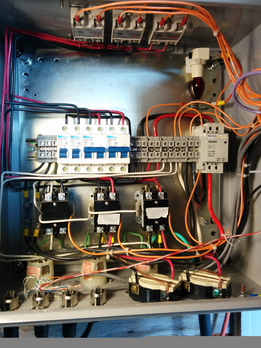
Oh, for the heck of it- I'll post my pics. It has a lot to critique as it was a first attempt. I would do it differently if I did it over - better organization, maybe use less wires. But it works! Haven't killed anyone yet. Has a small problem with switches not lighting up at proper time, but I may have that sorted. Can't really tell from the pics what's going on too well. But maybe someone can see this and figure out how to do it better themselves. Pics are always worth a thousand-some words. I left space above the breakers in case I wanted to someday do a BCS or similar system, though I wish I had more space below the contactors. The christmas tree light suffices as the resister for the panic button.

control-panel1-65536.jpg


control-panel2-65537.jpg
 
Only your hot lines should run through the switches. If you have 120v lights (or lighted switches), the light needs both a hot and a neutral.
 
I've been reading through the forums and can't find a similar scenario. I currently have a 120v control panel with two separate circuits; one for the pumps and one dedicated for the HERMS. Now I want to upgrade to 240V. I recently discovered that I have a 240V location at the pool pump timer. For those of us that have a 240V source with no neutral (H-H-G), can I simply run a 240 V (L1, L2, G) into the control panel, and a separate 120V circuit (L, N, G) into the control panel. Then I would run the L1 and L2 to the contactor poles and output side of the SSR, and then use the 120V circuit to control the PID, contactor coils, and 120V pumps. All circuits would be separated except for the ground. I saw something similar but much more complicated on page 67, and the only other option i know of is to run the 3 - 4 wire in a new spa panel. I appreciate any pointers.
 
I've been reading through the forums and can't find a similar scenario. I currently have a 120v control panel with two separate circuits; one for the pumps and one dedicated for the HERMS. Now I want to upgrade to 240V. I recently discovered that I have a 240V location at the pool pump timer. For those of us that have a 240V source with no neutral (H-H-G), can I simply run a 240 V (L1, L2, G) into the control panel, and a separate 120V circuit (L, N, G) into the control panel. Then I would run the L1 and L2 to the contactor poles and output side of the SSR, and then use the 120V circuit to control the PID, contactor coils, and 120V pumps. All circuits would be separated except for the ground. I saw something similar but much more complicated on page 67, and the only other option i know of is to run the 3 - 4 wire in a new spa panel. I appreciate any pointers.

Yes, you can do what you propose. Just make sure you have separate GFCI protectors for the 240 and 120 circuits.

Brew on :mug:
 
I have a 2352 pid and I'm having trouble with the alarm. I set the alarm to 155 for steeping and it goes off at temp; however when I change the alarm to 205 for boiling temp it won't go off unless I cycle through the setting a few times. Any insight on what I'm doing wrong?
 
P-J,

I am looking to do a 10gal Two Vessel Brewing system for 5gal batches using a 2000watt RIMS set up, a HLT/BK with a 4500-5500watt element, and one chugger pump. I was wondering if you could suggest which one of your diagrams would be the best for this. I would be using the RIMS, Pump, and HLT/BK at the same time for Mashing and Maintaining my Sparge Water Temp. Please let me know what you think when you have a spare moment.

Thank You,

Dogman
 
30a 5500 2 Element 2 Pump EStop Single PID
Auberin-wiring1-a4-5500w-30a-e-stop.jpg


50a 5500 3 Element 3 outlet BCS 460 RIMS
BCS-460-wiring-2-4.jpg


50a 5500 2 Element 4 outlet BCS 460
BCS-460-wiring-2-4-c.jpg


30a 5500 2 element 3 outlet estop BCS 460
Kenneth-BCS-460-wiring-2-4a.jpg


30a 5500 2 element 2 pump single PID estop
Auberin-wiring1-b4-5500w-30a-e-stop-8b.jpg


120v 2000 2 Element 2 pump single PID
Auberin-wiring1-a4-simple-1.jpg


30A 5500 Single Element Single pump dual PID?
Auberin-wiring1-a4-5500w-30d.jpg


50a 5500 2 element 2 pump 2 PID
Auberin-wiring1-a11a-RM-SYL-2352-5500w.jpg


120v 2000 Single Element Single Pump Single PID EStop
Auberin-wiring1-a4-2000w-BIAB-120V-A.jpg


50a 4500 2 Element 2000w RIMS 2pump 3PID EStop
Auberin-wiring1-a13-Rob-May-SYL-2352-4500w.jpg


50a 5500 2 Element 2 PID 2 Pump Estop
Auberin-wiring1-a11a-SWA-2451-5500w-s.jpg


40a 5500 2 Element 2 PID 2 Pump Estop
Auberin-wiring1-a11a-SYL-2352-5500w.jpg


Could I use this for my Two Vessel build? Just take away one element and one pump.
 
Could I use this for my Two Vessel build? Just take away one element and one pump.

I assume you are asking about this particular schematic. Is that correct?

Auberin-wiring1-a13-Rob-May-SYL-2352-4500w.jpg

If that's what you want, then it would end up looking something like this:

Kettle+RIMS Control Schematic.jpg

Brew on :mug:
 
Last edited:

Latest posts

Back
Top