sicktght311
Well-Known Member
- Joined
- Oct 16, 2018
- Messages
- 684
- Reaction score
- 303
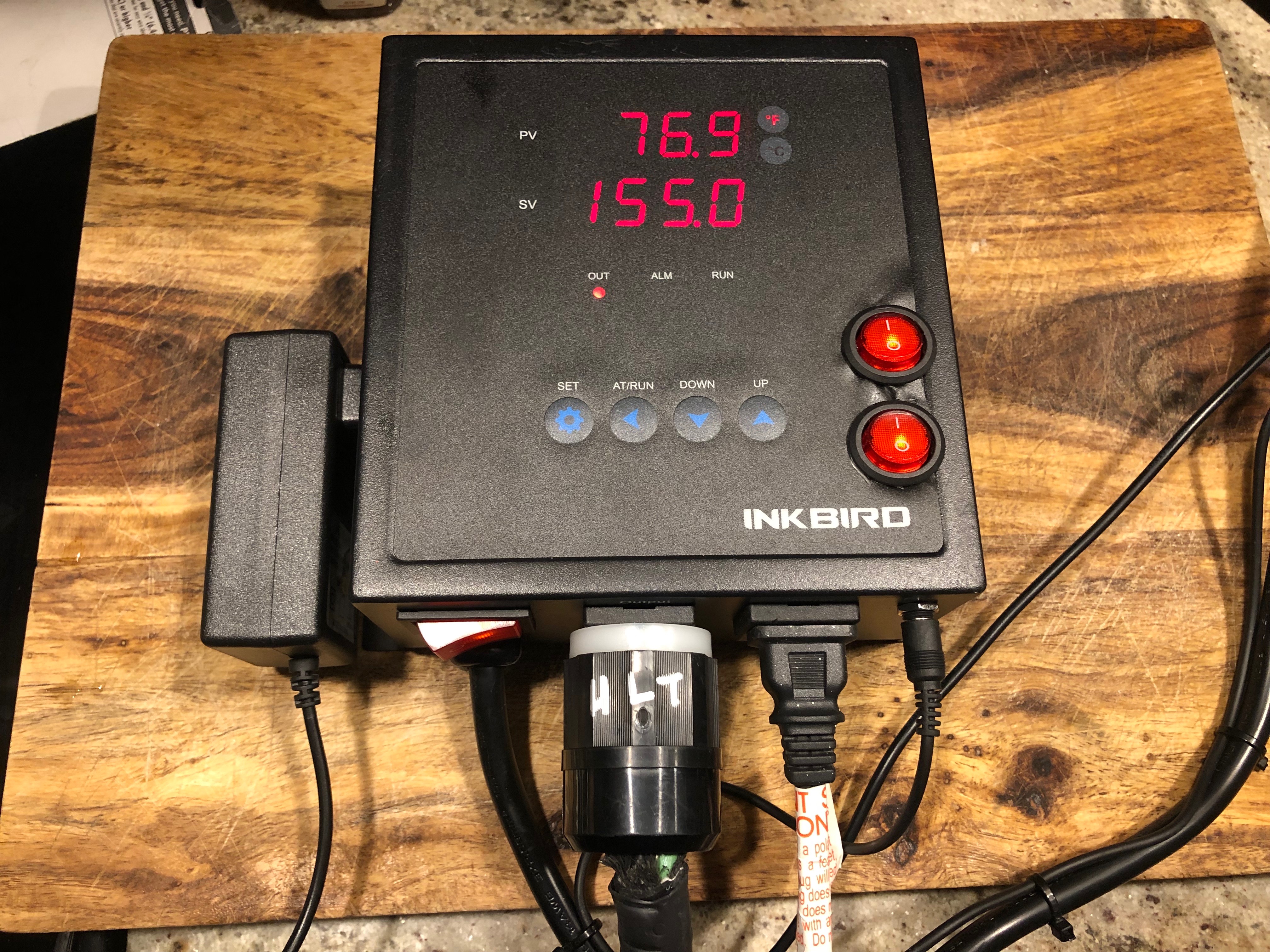
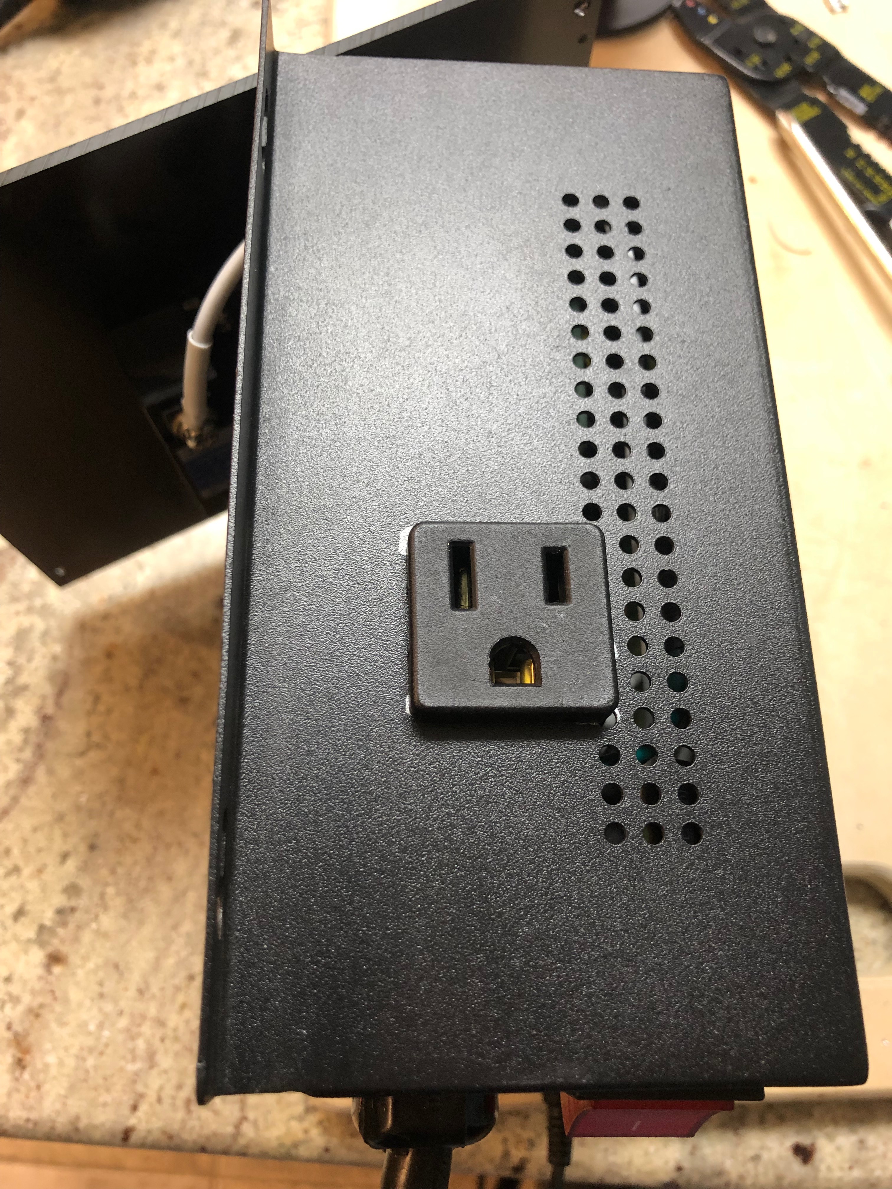
So i'm in the process of modding my IPB-16 to use as a temporary controller until i get around to building a Kal style 120v panel for my e-herms system, and as i had it open, it got me thinking......
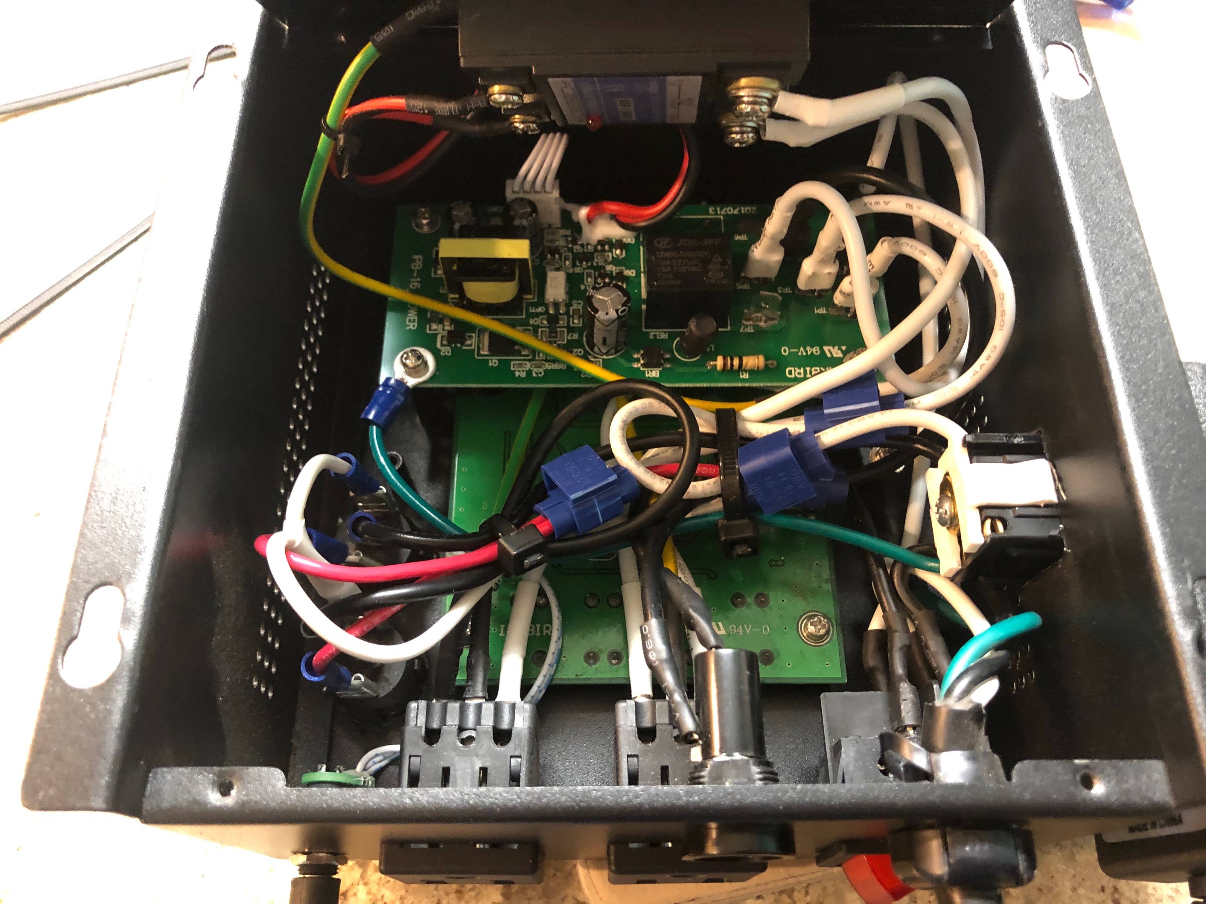
1) I have 2 pumps. One Mark II pump as my wort pump, and a tan DC solar pump permanently plumbed into my HLT output for my water pump. Obviously i can do the pump mod on the IPB16 for the single pump switch from the alarm output, which i'm doing anyway, but whats to stop me from splicing another 120v line off the same pre switch alarm output, to another switch, and cutting a square hole in the side of the IPB16 and placing a second panel mounted 120v outlet for the solar pump? That way i can control both pumps from the single device....
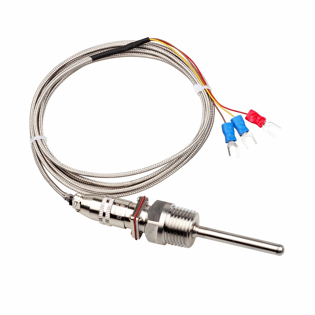
2) Going even further.....then i could easily replace the 1/8" headphone PT100 sensor plug, with two Auber RTDCON panel mount connectors, one for the HLT output, one for the boil kettle, and use a small on/off/on DPDT switch to toggle between the two new 1/2" NPT Auber sensor inputs to the PID when i want to switch from Mash to Boil/Chill.
Seems like these are both fairly easy to do mods with typical everyday wiring knowledge which i have, and a steady hand with a step bit/dremel cutting wheel. This turns the IPB16 into pretty much a start to finish controller for a 3 vessel 120v Herms system
OTHER THAN.......unplugging the HLT element, and plugging in the Boil Kettle element. That is the last piece of the puzzle that a normal panel takes care of with two DPDT contactors and a on/off/on switch. So then
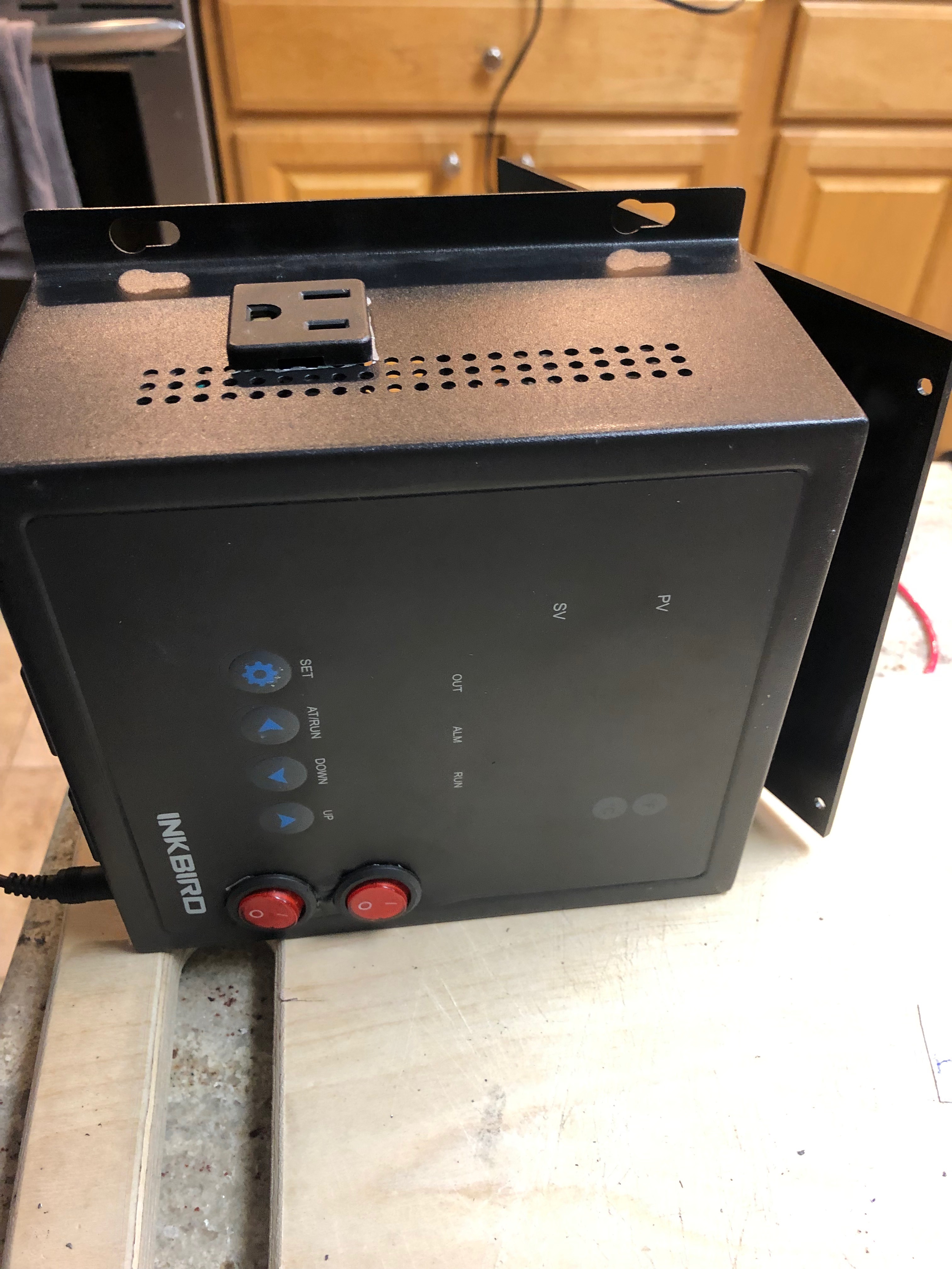
3) Why couldn't i place two 240v DPDT 120v coil contactors into a small/medium project box, with two 120v panel mount outlets, a 3 way on/off/on switch, and wire it up so the IPB16's element output plugs into the "Element selection box", and then switch between the two elements. Everything stays plugged in, the IPB16 is the overall brains of the system, and everything functions as a normal all in one panel.
The only issue i cant seem to get past, is the need for a 120v constant power hot line to power the contactor coils. You cant really splice off the element hot line coming into the selector box, because its post SSR so it would be pulsing on and off, and would overload a contactor. Could it just be as simple as splicing a hot 120v (post fuse) line in the ipb16, running it out of the IPB16 through a hole, into the element selector box, and using that in the on/off/on switch to power whichever contactor's coil i'm selecting? I just hate not having things detachable between the IPB16, and the Selector box, and seems like an added danger having a single hot lead coming out of the IPB16 and into a project box.
1) I have 2 pumps. One Mark II pump as my wort pump, and a tan DC solar pump permanently plumbed into my HLT output for my water pump. Obviously i can do the pump mod on the IPB16 for the single pump switch from the alarm output, which i'm doing anyway, but whats to stop me from splicing another 120v line off the same pre switch alarm output, to another switch, and cutting a square hole in the side of the IPB16 and placing a second panel mounted 120v outlet for the solar pump? That way i can control both pumps from the single device....
2) Going even further.....then i could easily replace the 1/8" headphone PT100 sensor plug, with two Auber RTDCON panel mount connectors, one for the HLT output, one for the boil kettle, and use a small on/off/on DPDT switch to toggle between the two new 1/2" NPT Auber sensor inputs to the PID when i want to switch from Mash to Boil/Chill.
Seems like these are both fairly easy to do mods with typical everyday wiring knowledge which i have, and a steady hand with a step bit/dremel cutting wheel. This turns the IPB16 into pretty much a start to finish controller for a 3 vessel 120v Herms system
OTHER THAN.......unplugging the HLT element, and plugging in the Boil Kettle element. That is the last piece of the puzzle that a normal panel takes care of with two DPDT contactors and a on/off/on switch. So then
3) Why couldn't i place two 240v DPDT 120v coil contactors into a small/medium project box, with two 120v panel mount outlets, a 3 way on/off/on switch, and wire it up so the IPB16's element output plugs into the "Element selection box", and then switch between the two elements. Everything stays plugged in, the IPB16 is the overall brains of the system, and everything functions as a normal all in one panel.
The only issue i cant seem to get past, is the need for a 120v constant power hot line to power the contactor coils. You cant really splice off the element hot line coming into the selector box, because its post SSR so it would be pulsing on and off, and would overload a contactor. Could it just be as simple as splicing a hot 120v (post fuse) line in the ipb16, running it out of the IPB16 through a hole, into the element selector box, and using that in the on/off/on switch to power whichever contactor's coil i'm selecting? I just hate not having things detachable between the IPB16, and the Selector box, and seems like an added danger having a single hot lead coming out of the IPB16 and into a project box.
")