Well finally back after finding some time to do some testing.....can't say that I found anything wrong so here's what I did....was suspicious that maybe the 1 wires were bad so used one from another vendor (Oscsys to be specific) and hooked it up...didn't show up.....when the first offerings were offered by BrewPi I purchased one and have it assembled and it's totally a different animal on how it's put together so figured it would work with either one of the 1 wire sensors....no deal.....problem is both systems get to the same place and don't show any 1 wires no matter which I use....obviously a problem somewhere but since they both have the same trouble seeing the sensor, I'm at a loss.....again any help more than welcome....thanks
You are using an out of date browser. It may not display this or other websites correctly.
You should upgrade or use an alternative browser.
You should upgrade or use an alternative browser.
HOWTO - Make a BrewPi Fermentation Controller For Cheap
- Thread starter FuzzeWuzze
- Start date

Help Support Homebrew Talk - Beer, Wine, Mead, & Cider Brewing Discussion Forum:
This site may earn a commission from merchant affiliate
links, including eBay, Amazon, and others.
- Status
- Not open for further replies.
If that was a Rev A BrewPi with their shield and all it's fairly different from their current configuration - it definitely uses the AVR pins differently, for instance. But if you installed the correct packages and the appropriate AVR code (there's firmware specific to their original configuration) it should certainly work.
As for what I guess is your new build, a refresh of that configuration would be helpful for context. Especially how you have connected the temperature sensor. And what the specific problem is as well...
Cheers!
As for what I guess is your new build, a refresh of that configuration would be helpful for context. Especially how you have connected the temperature sensor. And what the specific problem is as well...
Cheers!
So after reading this thread for awhile, and the STC-1000+ thread, the inspiration has finally spilled over and I jumped in. These micro controllers and raspberry Pi's are too damn cool not to play with. So I wanted to build a controller that was compact and clean, as my current old STC-1000 build is a bit slapdash. I am putting everything into a radio shack small black project box, using 1/4 inch stereo audio jacks on the box for my thermocouples, panel mount flush plugs for switches and a reverse PC power inverter style, fused switched male power input. The outer looks of the box I want to look alot like the "black box" build that is super clean. You guys have inspired me so I want to photo log my build to hopefully inspire others.
I have alot of spare parts around so a complete part list would be hard produce but at the end I'll try to put it up. This would not be the "dirt cheap" goal as mentioned frequently by fuzzy, but only because of a few extra connectors, and it may only add up to 30 or so bucks over the cost of the base components. I had plenty of SD cards and NOOBS was super easy (cut and paste on a formated drive!) I had monitors, keyboard, usb, and wifi dongle (although pretty big). I also had plenty of spare connectors, wires, solder, and very importantly plastic spacers (as you will see), from a past life.
I have seen some builds with the RPI outside of the relay/arduino components, but I wanted all components, and the USB connectors for them to all be contained in the box. The outside switch for my main power is an "emergency switch" to shut it all off if I need to, but I don't want to have components visible.
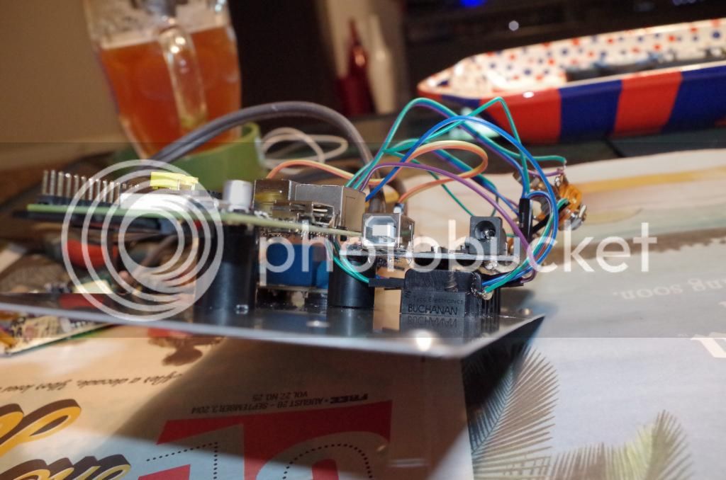
This is my first installment, most of the "guts" getting placed and connected:
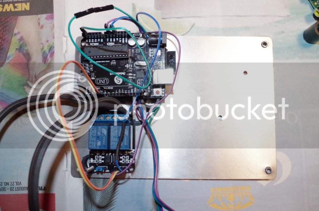
First I installed the terminal block and the relays on the metal plate. You need to line up your components with their screw holes and pilot drill to get it lined up properly. I used different length plastic spacers to pull each board off the metal plate to avoid any shorts and to stagger each item, elevating them and making more space to make everything more compact

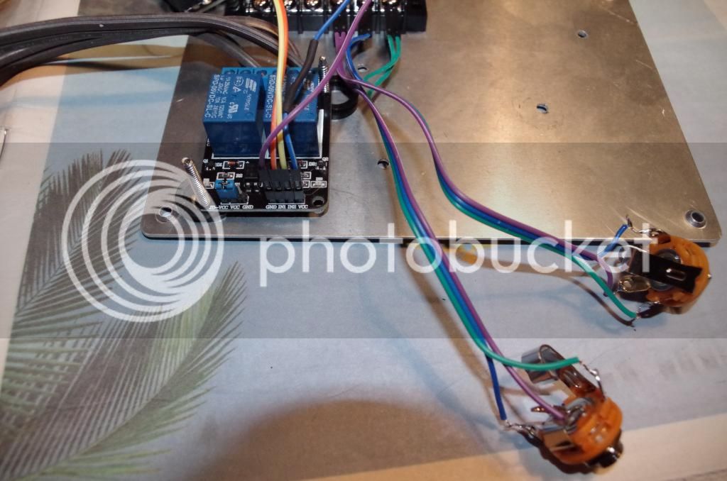
here are the panel, female side of the 1/4 audio jacks
here is the terminal block under the arduino, it is just narrow enough to avoid all the screw holes from the arduino too


Here is the arduino elevated over the terminal block

Another view

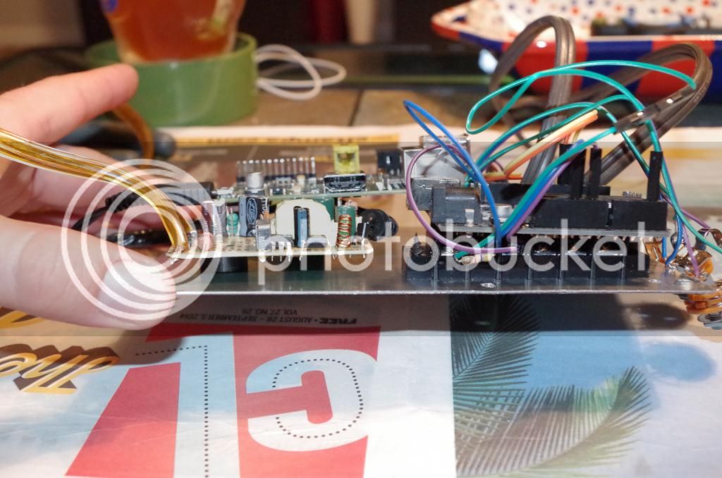
Next I added the RPI on the board, it is the tallest item so it has the longest spacers to rise it above the rest.


Another view
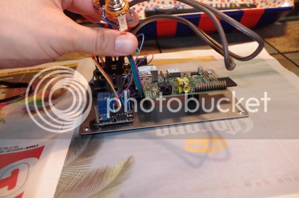

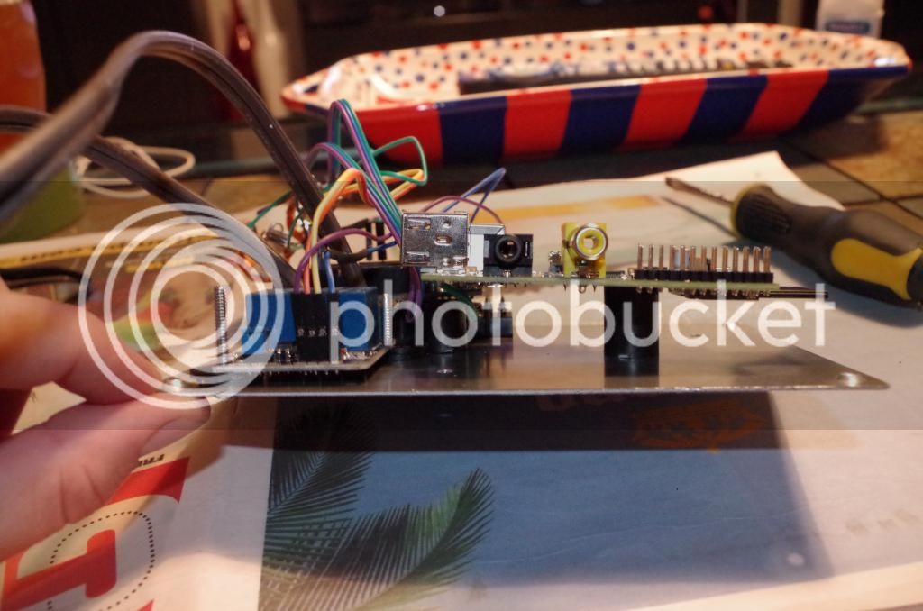
Next I used an old blackberry charger, broke all the plastic off and soldered some leads to the board, to provide power via micro usb to the Pi. I had to drill a small hole in the board, avoiding any electric contacts and shorts of course, to mount it the the back plate. Note I shortened the usb charger cable which was way too long.
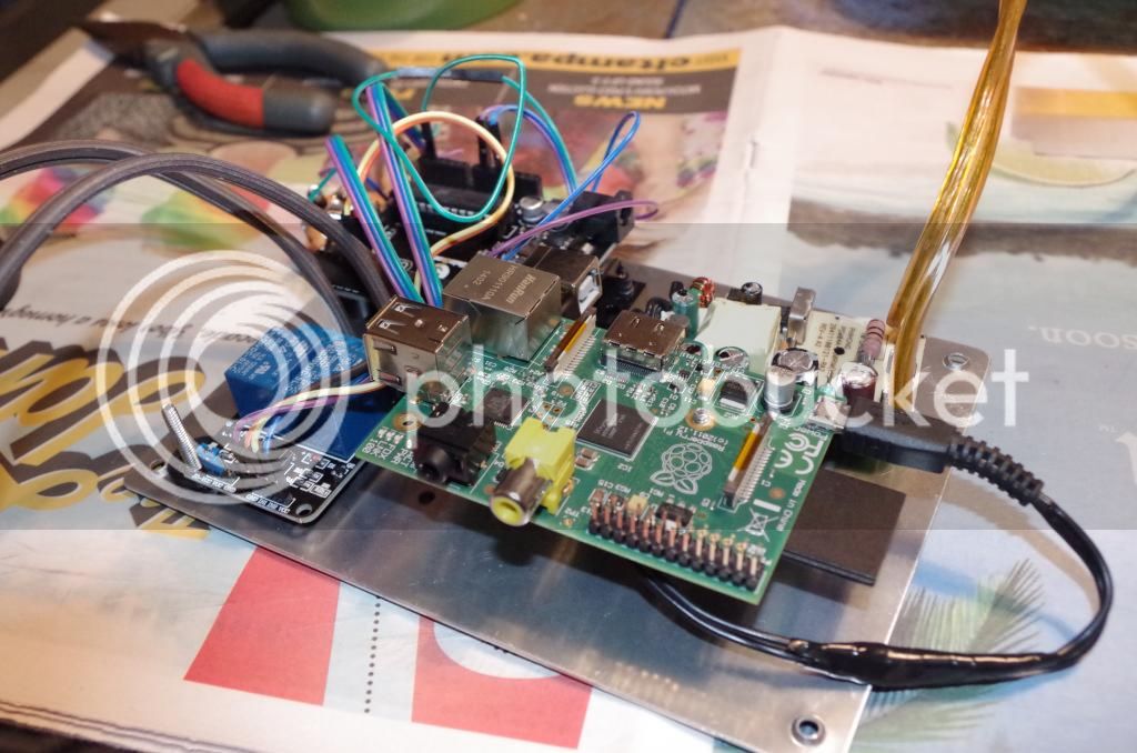

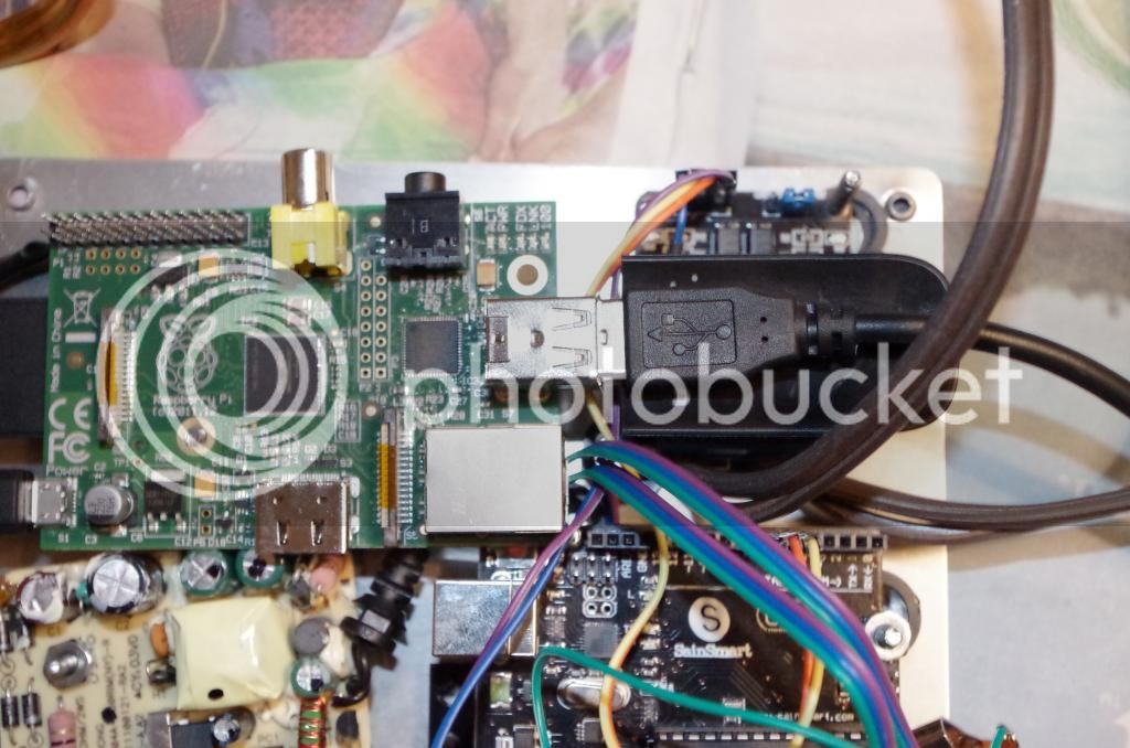
Almost everything above
Big ass network adapter
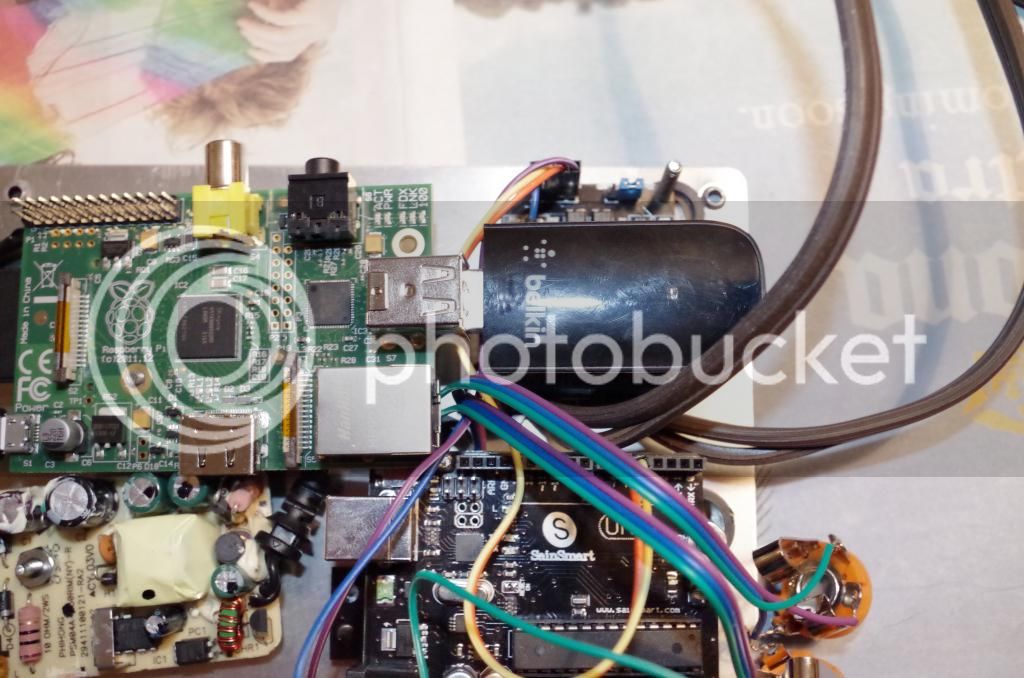
USB on Pi going to Arduino
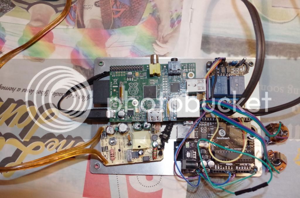
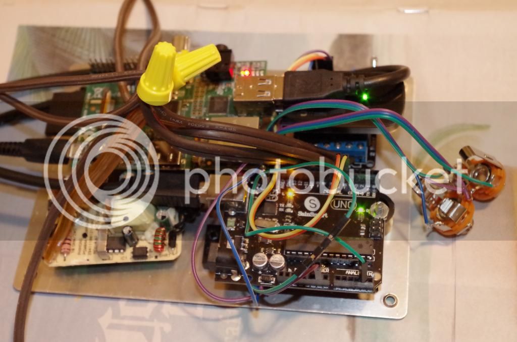
And finally a temporary dry run to make sure that my connections didn't get disloged:
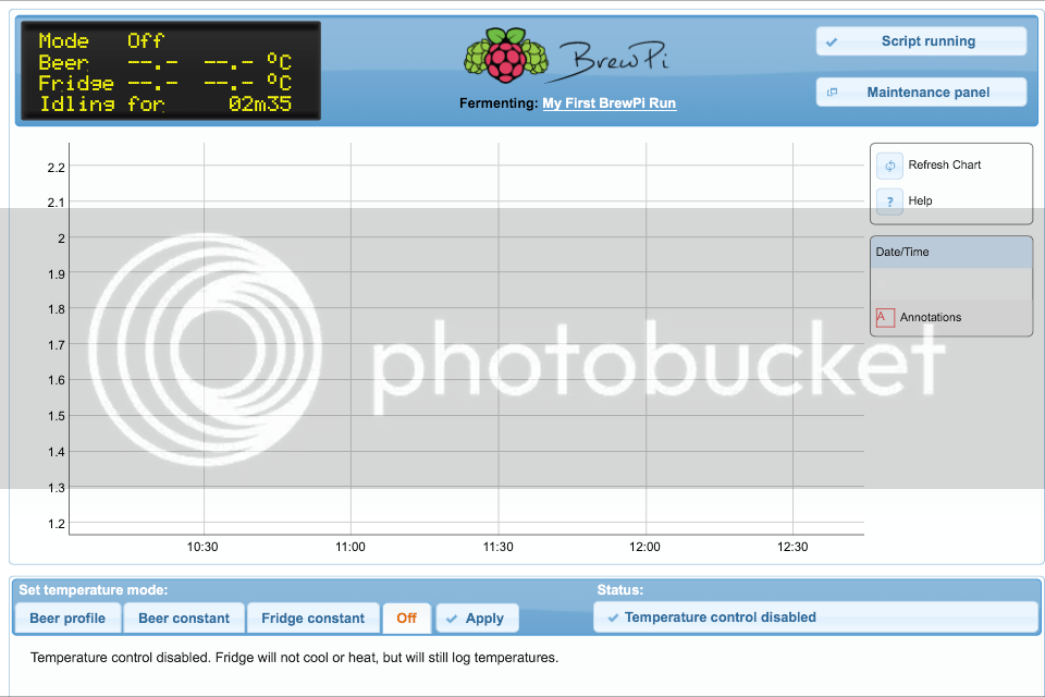
and my Iphone screen shot immediately after!!!
I have not hooked up the temp sensors of course. Also you must install your raspbian and brewPI software on the devise before all of this! I am waiting on my other connectors to put it into the box and cross my fingers that it all fits. I will have to get a right angle micro USB connector of course, as the crackberry one is too long and won't fit in the box as it sits.
I am going to post up some additional pictures when it is all in the box, and try to get a parts list going. Just glad that it is all working so far.
Cheers all,
I have alot of spare parts around so a complete part list would be hard produce but at the end I'll try to put it up. This would not be the "dirt cheap" goal as mentioned frequently by fuzzy, but only because of a few extra connectors, and it may only add up to 30 or so bucks over the cost of the base components. I had plenty of SD cards and NOOBS was super easy (cut and paste on a formated drive!) I had monitors, keyboard, usb, and wifi dongle (although pretty big). I also had plenty of spare connectors, wires, solder, and very importantly plastic spacers (as you will see), from a past life.
I have seen some builds with the RPI outside of the relay/arduino components, but I wanted all components, and the USB connectors for them to all be contained in the box. The outside switch for my main power is an "emergency switch" to shut it all off if I need to, but I don't want to have components visible.
This is my first installment, most of the "guts" getting placed and connected:

First I installed the terminal block and the relays on the metal plate. You need to line up your components with their screw holes and pilot drill to get it lined up properly. I used different length plastic spacers to pull each board off the metal plate to avoid any shorts and to stagger each item, elevating them and making more space to make everything more compact

here are the panel, female side of the 1/4 audio jacks

here is the terminal block under the arduino, it is just narrow enough to avoid all the screw holes from the arduino too


Here is the arduino elevated over the terminal block

Another view

Next I added the RPI on the board, it is the tallest item so it has the longest spacers to rise it above the rest.


Another view


Next I used an old blackberry charger, broke all the plastic off and soldered some leads to the board, to provide power via micro usb to the Pi. I had to drill a small hole in the board, avoiding any electric contacts and shorts of course, to mount it the the back plate. Note I shortened the usb charger cable which was way too long.


Almost everything above

Big ass network adapter

USB on Pi going to Arduino

And finally a temporary dry run to make sure that my connections didn't get disloged:

and my Iphone screen shot immediately after!!!

I have not hooked up the temp sensors of course. Also you must install your raspbian and brewPI software on the devise before all of this! I am waiting on my other connectors to put it into the box and cross my fingers that it all fits. I will have to get a right angle micro USB connector of course, as the crackberry one is too long and won't fit in the box as it sits.
I am going to post up some additional pictures when it is all in the box, and try to get a parts list going. Just glad that it is all working so far.
Cheers all,
makez_beer
New Member
I just want to say thanks to Fuzze for posting this, and to all that have provided such great information in this thread. I completed my build yesterday and have been running a "wet test" overnight.
Really happy with even the "base level" build functionality.
Really happy with even the "base level" build functionality.
OP
OP
FuzzeWuzze
I Love DIY
Good to hear! Welcome to HBT lol.


USB hubs.
Anyone have a recommendation on one that does work?
I can say *don't* use one of these
http://www.amazon.com/dp/B005C32NMS/?tag=skimlinks_replacement-20
It doesn't work - drops the signal every once in a while, then it will work if I replug. Junk.
Also, I was using a SainSmart nano clone, and found it didn't re-initialize the connection with the computer at reboot, only after re-plugging. I got another nano clone(?) on ebay http://www.ebay.com/itm/111244914166?_trksid=p2059210.m2749.l2649&ssPageName=STRK:MEBIDX:IT
This one works better for me, and it's cheaper! Once every thing comes in, I'll be back on track with the build.
Anyone have a recommendation on one that does work?
I can say *don't* use one of these
http://www.amazon.com/dp/B005C32NMS/?tag=skimlinks_replacement-20
It doesn't work - drops the signal every once in a while, then it will work if I replug. Junk.
Also, I was using a SainSmart nano clone, and found it didn't re-initialize the connection with the computer at reboot, only after re-plugging. I got another nano clone(?) on ebay http://www.ebay.com/itm/111244914166?_trksid=p2059210.m2749.l2649&ssPageName=STRK:MEBIDX:IT
This one works better for me, and it's cheaper!
Once every thing comes in, I'll be back on track with the build.
Last edited by a moderator:
wbarber69
Well-Known Member
- Joined
- Oct 13, 2013
- Messages
- 2,191
- Reaction score
- 263
I was able to get 1 arduino working on the hub with the shortest USB cables I could find
but it doesn't really solve the problem. As soon as I hooked up the second one problems arose. I'll see what I can get out of these monoprice ones. Sometimes their gear outperforms even the most expensive and sometimes it's the cheapest garbage you can find. Only time will tell.
USB hubs.
Anyone have a recommendation on one that does work?
I can say *don't* use one of these
http://www.amazon.com/dp/B005C32NMS/?tag=skimlinks_replacement-20
It doesn't work - drops the signal every once in a while, then it will work if I replug. Junk.
[...]
lol! That's the same hub I've been running with a pair of Unos for months.
That much works perfectly, but if I add a wireless adapter - wifi or quasi-bluetooth - it'll eventually cause the 'Pi to shoot its USB root complex.
Hopefully someone will find a more tolerant hub...
Cheers!
Last edited by a moderator:
wbarber69
Well-Known Member
- Joined
- Oct 13, 2013
- Messages
- 2,191
- Reaction score
- 263
Running for 30 minutes now with absolutely no errors. And this hub will power the pi b+ from upstream usb connection ") now to start hooking up probes to see how it performs while logging. Then I'll hook up the one-wire actuators and start clicking some relays.
now to start hooking up probes to see how it performs while logging. Then I'll hook up the one-wire actuators and start clicking some relays.
now to start hooking up probes to see how it performs while logging. Then I'll hook up the one-wire actuators and start clicking some relays.wbarber69
Well-Known Member
- Joined
- Oct 13, 2013
- Messages
- 2,191
- Reaction score
- 263
this is the hub im using
http://www.monoprice.com/Product?c_id=103&cp_id=10307&cs_id=1030702&p_id=10065&seq=1&format=2
http://www.monoprice.com/Product?c_id=103&cp_id=10307&cs_id=1030702&p_id=10065&seq=1&format=2
wbarber69
Well-Known Member
- Joined
- Oct 13, 2013
- Messages
- 2,191
- Reaction score
- 263
Looks super promising so far. I've got all 4 up and running and I can reprogram each one with no errors. And I'm officially running off power from the hub. I've eliminated even 1 more cable/wire to deal with.
EDIT: I should note the monoprice hub did not come with a power supply. I'm using the one that came with the bs hub from belkin I bought first.
EDIT: I should note the monoprice hub did not come with a power supply. I'm using the one that came with the bs hub from belkin I bought first.
Got my thermowell in today. Fits in the grommets I use for the airlock perfectly. I'll have to drill another hole and add a grommet. Getting some OT next week so hopefully I can fix this freezer or buy another freezer before I brew again.
The pics


wbarber69
Well-Known Member
- Joined
- Oct 13, 2013
- Messages
- 2,191
- Reaction score
- 263
The pics
That's so funny I was just doing the same thing to my big mouth bubblers


I like that threaded set up you have. After seeing you post them earlier in the thread I thought about gong that route. Unfortunately the red lid is curved and wasn't sure if it would be a PITA because of that.


Anyone know if you can share a single one wire DS18b20 bus across two arduinos? I *think* it can be done based on a single test that I did for 5 minutes.
That would enable 1 DS18b20 to measure external temp for freezer and fridge.
That would enable 1 DS18b20 to measure external temp for freezer and fridge.
Got it drilled.


RyanSweeney
Well-Known Member
Door switches can be shared
View attachment 223173
View attachment 223175View attachment 223176View attachment 223179
Do you have the code posted somewhere that shows how to get multiple stats screens on one page?
Looks super promising so far. I've got all 4 up and running and I can reprogram each one with no errors. And I'm officially running off power from the hub. I've eliminated even 1 more cable/wire to deal with.
Awesome! I'm ordering a couple right now.
EDIT: I should note the monoprice hub did not come with a power supply. I'm using the one that came with the bs hub from belkin I bought first.
lol! At least you salvaged the wall wart
Cheers!
wbarber69
Well-Known Member
- Joined
- Oct 13, 2013
- Messages
- 2,191
- Reaction score
- 263
Do you have the code posted somewhere that shows how to get multiple stats screens on one page?
Yeah it's in this forum fuzze posted it to the original post in the links section
Yeah it's in this forum fuzze posted it to the original post in the links section
Which, btw, I forgot to thank FuzzeWuzze for taking the time to do.
I've used it a half-dozen times already to locate my own posts
Cheers! (and thanks, Fuzze!
)Anyone know if you can share a single one wire DS18b20 bus across two arduinos? I *think* it can be done based on a single test that I did for 5 minutes.
That would enable 1 DS18b20 to measure external temp for freezer and fridge.
Sharing a One-Wire bus between two unaware entities isn't gonna work well.
If you were to implement a semaphore side-band signalling protocol it could work very well indeed, but that's a fairly complex paradigm to implement that's also likely to have side-effects running up into user code.
Probes are effin' cheap. Strap a pair of them together...
Cheers!
wbarber69
Well-Known Member
- Joined
- Oct 13, 2013
- Messages
- 2,191
- Reaction score
- 263
Sharing a One-Wire bus between two unaware entities isn't gonna work well.
If you were to implement a semaphore side-band signalling protocol it could work very well indeed, but that's a fairly complex paradigm to implement that's also likely to have side-effects running up into user code.
Probes are effin' cheap. Strap a pair of them together...
Cheers!
For my setup, my intention is to not have any room temp sensors. Too much extra data to log. I've allowed my test setup to run for like 2 months straight without changing anything and once my graph got that big it started dragging down my browsers and crashing my phone.
I had one run duplicated across two BrewPi instances that both went on for over a month with all three probes. No problems. GS4
But the fact is the Room Temperature probe is only interesting to the interested. It has no effect on the governing BrewPi code, so if something had to be cast overboard to lighten the load, that's the logical one to toss...
Cheers!
But the fact is the Room Temperature probe is only interesting to the interested. It has no effect on the governing BrewPi code, so if something had to be cast overboard to lighten the load, that's the logical one to toss...
Cheers!
wbarber69
Well-Known Member
- Joined
- Oct 13, 2013
- Messages
- 2,191
- Reaction score
- 263
Day_tripper I'm letting the hub run unpowered overnight to see how it performs. Hopefully you won't need to buy a power supply. Haven't seen any errors so far
.
And I'm running iceweasel in an xinit type kiosk mode. So far I haven't gotten it to freeze up or puke out any errors.
I love monoprice!
And I'm running iceweasel in an xinit type kiosk mode. So far I haven't gotten it to freeze up or puke out any errors.
I love monoprice!
Power is not a problem, all my modules are running on their own 'warts.
Maintaining coherent communication with a heterogeneous USB device population behind the hub is the problem. I have a viable work-around should the (ridiculously inexpensive) hub of yours not play nice with a nic and an Uno or two, but it would be simpler if it does work out.
btw, that's one awesome Uno sandwich!
Cheers!
wbarber69
Well-Known Member
- Joined
- Oct 13, 2013
- Messages
- 2,191
- Reaction score
- 263
Yeah for real
if this thing holds out like it is now. I'm gonna buy one in every color. I love monoprice, every USB cable I'm using in this project came from there. And the cat6 cable the pi is using for network.
RyanSweeney
Well-Known Member
Yeah it's in this forum fuzze posted it to the original post in the links section
Found it. Thanks...to you AND to Fuzze! I got it up and running, but in a hidden page. My brewpi is available over the web but secured with a password. Anyone know of a way to have the LCD or LCD and graph displayed in a web page, but not the controls?
RyanSweeney
Well-Known Member
The lcd.php file in each instance will display only the lcd text for that particular instance if you just run lcd.php by itself.
Right, but then anyone can view the source on that page and see the URL to my brewpi, and without a password, they'll be able to control it also.
- Status
- Not open for further replies.
Similar threads
- Replies
- 3
- Views
- 1K
