How To: BrewPi LCD Add-On

Homebrew Talk - Beer, Wine, Mead, & Cider Brewing Discussion Forum

Help Support Homebrew Talk - Beer, Wine, Mead, & Cider Brewing Discussion Forum:

This site may earn a commission from merchant affiliate links, including eBay, Amazon, and others.
Hi guys

First of all, just want to say a massive thanks to day_trippr and fuzze for all the work they've put into the brewpi resources on this site. They are invaluable resources for putting this stuff together.

I recently got my build working on a breadboard with the lcd. I'm looking to move that circuit to the protoshield soon now that I've verified the parts are all OK, and then I plan on having a go at the backlight timeout and the rotary encoder. I just wanted to check something about the transistor for the timeout functionality. I have some transistors which came with a arduino kit, and I'm not sure if they would do the job here, or if I need to source the models mentioned earlier in this thread? The transistors I have are labelled BC547B.

Thanks for any help
 
Hi there,

In the circuit diagram a 2N2906 transistor is specified, which is a PNP transistor capable of switching 600mA, wired as a high-side switch. A BC547B is an NPN transistor, capable of switching 100mA, and usually used as a low-side switch.

You could use this transistor as I think the current rating is sufficient, but the action of the transistor is inverted. What this would mean is that the backlight brightness will be opposite of what is desired, i.e. 10% brightness (10% on and 90% off) would appear instead as 90% brightness (10% off and 90% on). To get around this you could alter the firmware to invert the signal that drives the backlight, or you could add a second BC547 transistor to invert the signal.

Or you could buy a 2N2906 (or equivalent) transistor. It's only being used as a switch, so almost any PNP transistor would do.
 
Sorry, I forgot to add, if you are using two BC547s, with one as an inverter, you need to re-wire the second transistor so that it switches the ground side of the backlight. In other words, connect pin 15 of the LCD module to 5V, then put the switching transistor in-line from pin 16 to GND.

Here's a good article about general-purpose transistors:
https://www.baldengineer.com/the-best-4-transistors-to-keep-in-your-parts-kit.html

tl;dr PNP: 2N3906 or BC557
 
For those still having scrambling issues. A work around is to have the LCD screen re-init periodically. Every 60s for example. After trying everything (with induction relays), this was the best solution I could find. I've been running the modified arudino image and scrambling hasn't been an issue.

If you want the uno hex and I can find a place to upload it.
 
Hi all again

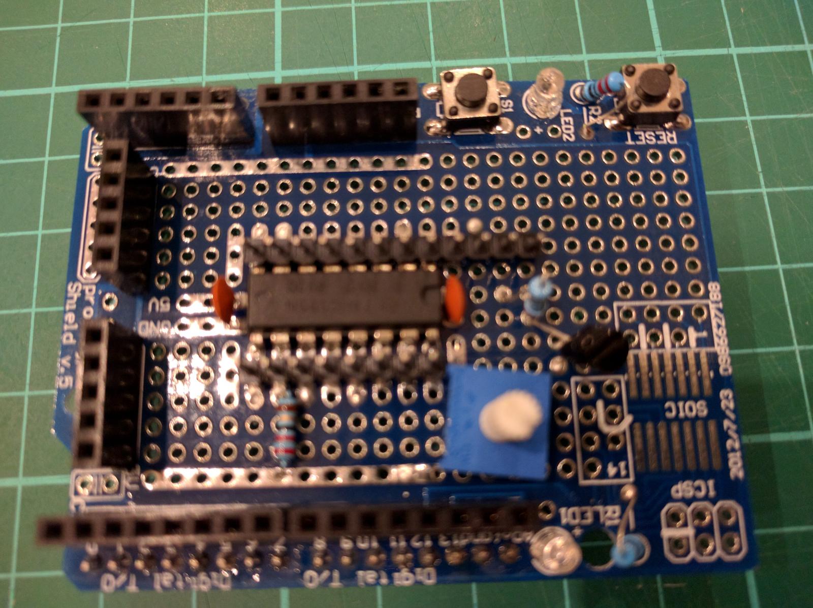
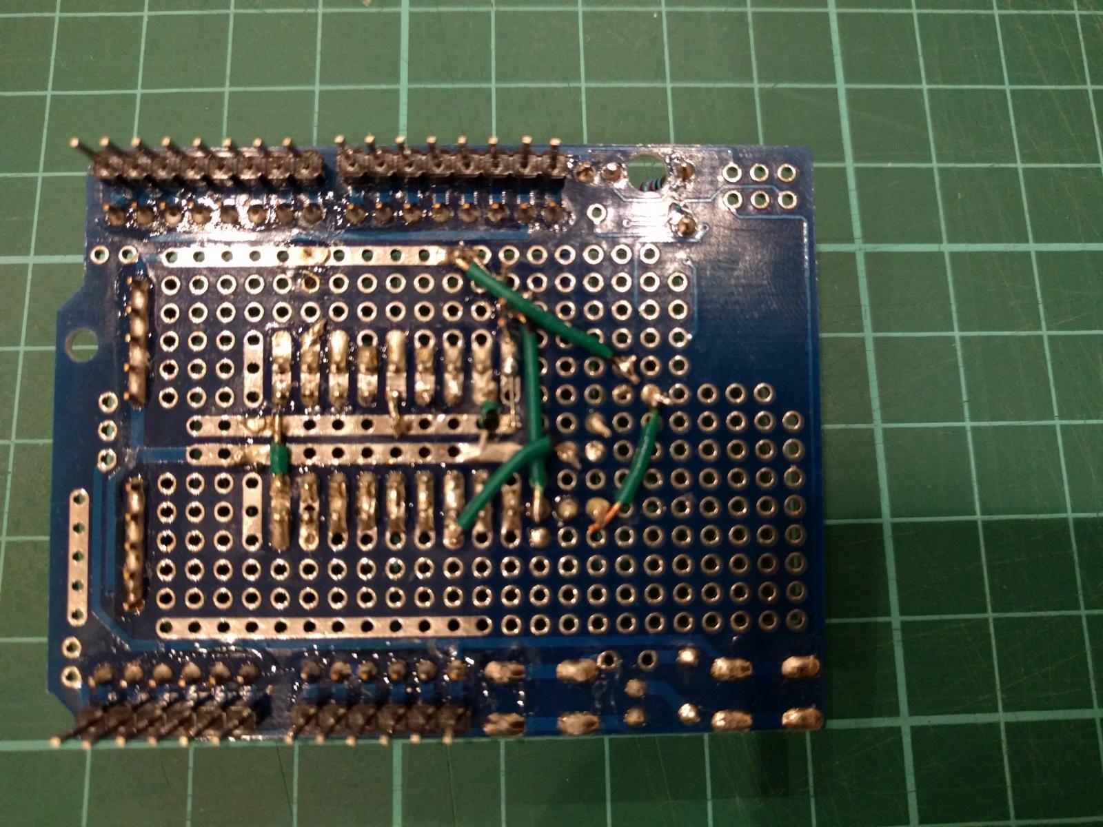
I got everything working including the rotary encoder and the backlight dimming with a PNP transistor. I've now tried to move everything from the breadboard onto the protoshield. I'll admit I'm not the finest at soldering, but I think I got all the basics for the LCD done. However, I am having a couple of issues, and I was wondering if anyone can give me any pointers on how to troubleshoot them.

Firstly, the LCD backlight is coming on, and the contrast pot is working fine. However, the display just shows two lines of squares, on the first and third line.

Secondly, if I connect the temperature sensors directly into the 5V/GND/A4 headers, the board ceases to boot properly and isn't even recognised by the brewpi. If I remove the protoshield and plug the sensors directly into the arduino, they work fine. I should note that I still have the resistor across the live/data lines of the temperature sensors in the choc block- I have not moved it onto the shield.

I appreciate it's hard (impossible?) to diagnose this from just my description, but any pointers for how to work out if any components have failed, or similar, would be appreciated. I have checked my connections with a multimeter, so I am pretty convinced that they are solid.

edit: fwiw, I've attached some pictures of my "handywork".

2016-02-06 23.44.31.jpg


2016-02-06 23.44.40.jpg
 
Last edited:
AFAIK the 'black boxes' are a problem with contrast.

Does turning the contrast pot have any visible effect? If not, maybe there is a short somewhere on the pot or the wiring path to the pot or display. Or maybe an open-circuit, or bad solder joint, or missed connection.

Regarding the sensor, my guess is that the pin order is now backwards compared with the breadboard. Double check your physical wiring with the schematic.

It's tedious, but the only way to troubleshoot is to trace each line of the schematic on the physical board and check for shorts or bad joints. Take a break for a while and come back to it.
 
[...]Firstly, the LCD backlight is coming on, and the contrast pot is working fine. However, the display just shows two lines of squares, on the first and third line.

That state is totally normal immediately following power up or reset. But if it persists more than a handful of seconds, it means the LCD is never receiving transactions from the Uno.

Secondly, if I connect the temperature sensors directly into the 5V/GND/A4 headers, the board ceases to boot properly and isn't even recognised by the brewpi. If I remove the protoshield and plug the sensors directly into the arduino, they work fine. I should note that I still have the resistor across the live/data lines of the temperature sensors in the choc block- I have not moved it onto the shield.

Has to be a wiring error somewhere.

I appreciate it's hard (impossible?) to diagnose this from just my description, but any pointers for how to work out if any components have failed, or similar, would be appreciated. I have checked my connections with a multimeter, so I am pretty convinced that they are solid.

edit: fwiw, I've attached some pictures of my "handywork".

Unless you're using Dupont jumpers between the shift register and the IO headers, there's a lot of wire missing...

Cheers!
 
That state is totally normal immediately following power up or reset. But if it persists more than a handful of seconds, it means the LCD is never receiving transactions from the Uno.


Has to be a wiring error somewhere.


Unless you're using Dupont jumpers between the shift register and the IO headers, there's a lot of wire missing...

Cheers!

There is a lesson in all of this. When frustrated and tired, go to bed and come back the next day. I was running wires from the IO headers to the shift register, but there were a couple of obvious mistakes in my wiring that fresh eyes saw immediately. That seems to have sorted both issues, and it's all up and running. Just the rotary controller to go now!
 
That's a few revs behind what's available - 0.2.10 iirc - but most of my minions are running 0.2.3 anyway.

I see, the latest is in firmware, brewpi-avr is not longer maintained. I 'll try to compile the latest version tonight.

I'll grab a copy and when I get a chance I'll give it a spin.

Cheers! :mug:

[edit] Whoops! I get a 404 from https://docs.google.com/uc?id=0B_iwvoOIaQnERUdMYTBxUlRDVU0&export=download

Try the link again and let me know if you have trouble.
 
There is a lesson in all of this. When frustrated and tired, go to bed and come back the next day. I was running wires from the IO headers to the shift register, but there were a couple of obvious mistakes in my wiring that fresh eyes saw immediately. That seems to have sorted both issues, and it's all up and running. Just the rotary controller to go now!

Excellent!

Cheers!
 
Tried to add a screen this weekend. I think I messed up some of the wiring.

6PWlzCEcEu_jL30TY4nGorfBKyIBVubpfnv1js5fMY80FAsnb8lvPzV4JJZ2zxRFNbf1bVCUWEBwkAmnXa1gG2TkrmsL8fdo96owbb5hNt92mcGOF5psMtVrvZHjfIZG9BZldcCKg6cj_eKdNAUSeTzKuWLDaPjY5meJYpWx5GKRkSVB1oapJKjVrl-XSHggkdPE-K0jteAin8pW5PSsQH23Y9zj6jVxwAiwyax6j1buEbElAkwcnQUTRHjj7UHMAEcjbGdQLlFH6qebWdNl8i8n62bok_phUXSPvbaZx2Fqssfq5kQQ7Tvhl_ubmSF8nGhsayOdo7m7cCcpfjP5Yg_P7rnME5pq-dK_Mq8Z5GPc6pTS-pQVDBZu_wTuoLZS71wFbZe3KviFb5mXcYLLFPGiibwxMpWGZtkESNkssibs5EJvhaN9hZ5Pjbzlcu3shVntIsQHsqCpe7jtvw2oJV_Re3nAMAdsanQl-f2TwkgJiQhSO6ggbIjyIrShVCoY3hG8ad9h7cBmOpRRbau9-uxxWPuvuxlwel_DQiK2OKhnU9BHfXIHnbzT4PqEHXoOzSBG_Q=w1469-h826-no


Need to go double check everything tonight.

Quick question. Do I really need 4 separate capacitors like is shown? I had a single one that was close to the right size and used that. If it's critical I'll find 4 smaller.
 
Presumably you mean the four caps along the top edge of the schematic? These are important as they are power-supply decoupling capacitors. One should be located near the '595, and others near the power input point and power take-off point for the LCD.

The circuit will work without them, but they are there to reduce the effects of electrical noise (which will definitely be present). If you don't have enough of them now you can still finish the circuit and add more later.
 
I see, the latest is in firmware, brewpi-avr is not longer maintained. I 'll try to compile the latest version tonight.

Try the link again and let me know if you have trouble.

So I tried loading this hex file, and ran into a couple of problems, one of which was a show-stopper.
The first was after loading the hex file BrewPi had issues restarting, and decided the right thing to do was to clear all the Uno settings. Arrgh!

Code:
Feb 11 2016 16:53:34 Opening serial port
Warning: Cannot receive version number from controller. Your controller is either not programmed yet or running a very old version of BrewPi. It will be reset to defaults.
Resetting EEPROM to default settings
INFO MESSAGE 15: EEPROM initialized
Now checking which settings and devices can be restored...
Warning: Cannot receive version number from controller after programming. 
Something must have gone wrong. Restoring settings/devices settings failed.

After I got the devices configured and the settings switched to °F and got the script running, I noticed that the Cool relay was hot, even though the gui said that device was 'inactive' and the LCD showed the system was Idling.

The device was properly configured (inverted channel, etc) but I then noticed if I clicked on its Apply button, the relay would open as it should. But within one second it closed again. And that's the show-stopper.

I reverted back to 0.2.10 - and this time all of the settings were properly restored automatically and the script started without any intervention.

When I get around to it I'll give this whole thing another try...

Cheers!
 
So I tried loading this hex file, and ran into a couple of problems, one of which was a show-stopper.

The first was after loading the hex file BrewPi had issues restarting, and decided the right thing to do was to clear all the Uno settings. Arrgh!
...


Well then, that didn't go as planned. :)


My guess is that because this is an older version bad things happened. From a fresh brewpi installation mine works well. Only a few lines of code was added to have the LCD reset every 60 seconds, nothing else was changed.


Still working on getting the latest version compiled. Not as easy as you would think...


Thanks for testing the hex file on another brewpi setup.
 
Hi guys,

Any progress or update on this? Since I'm lazy I would prefer to have ha hexfile that updates the screen instead of rebuilding my projectbox with SSR:s.

Chers!:rockin:

Well then, that didn't go as planned. :)


My guess is that because this is an older version bad things happened. From a fresh brewpi installation mine works well. Only a few lines of code was added to have the LCD reset every 60 seconds, nothing else was changed.


Still working on getting the latest version compiled. Not as easy as you would think...


Thanks for testing the hex file on another brewpi setup.
 
Well then, that didn't go as planned. :) [...]

The guts of my test "minion" sprawled on the desk have been reminding me I needed to revisit this.

This morning it had dawned on me that perhaps the 0.2.10 release I had been running uses the eeprom differently from the 0.2.4 version, and that attempting to preserve the settings from version to version was the wrong way to go.

So this time through the BrewPi burning procedure I did not preserve or reload the settings to the Uno eeprom, and instead set them all manually.
The result looks good so far: the Cool and Heat relays and all other devices are acting properly.

And now I can observe your handiwork:

- The display back light still dims and can be woken up via the rotary encoder.
- Every ~60 seconds you can see the display go through initialization and then population of the display values...
- ...at which point the back light promptly turns off.

Did not expect that last part.

The "stock" code keeps the back light turned on for 10 minutes from last use of the rotary encoder. The modded code can literally turn off the display a second after it's woken up via the encoder - it depends on where in the 60 second loop for the re-initialization timer you wake up the back light. In fact the first time I woke up the display it shut off within a second or so.

I've always thought the "stock" 10 minute timer for the display blanking was excessive - one minute would be plenty, imo. Otoh, the modded code goes a bit too far. I've woken the display up about ten times while writing this and two times it blanked within a couple of seconds. And now I'm noticing that you only get to see the first field of values populated - by the time display toggles to the other set of values, the back light has shut off.

If there is a way to hold the display back light for at least both frames to show (or, say, for ten seconds) that would be more friendly, but it's not a show-stopper.
I'm sure for folks plagued by screen scrambles this would be a godsend as it is...

[edit] and for anyone who didn't include the back light control, it'd be a straight replacement...

Cheers!
 
Right, I have everything in a project box and running. Has been keeping some water at temperature for 24 hours now. But, of course, I now have the scrambling issue. Not sure what caused it as it happened overnight. I've read the whole thread (I think) so I have some ideas and things to check. I just wondered, is it possible that powering the arduino independently rather than just daisy chaining from the pi on USB could help?
 
I just wondered, is it possible that powering the arduino independently rather than just daisy chaining from the pi on USB could help?

It definitely won't hurt, and easily could help. I did some DC measurements on the "5V" USB input on an Uno R3 using different USB cables and at best I was seeing 4.7V at the Uno end, and often closer to 4.5V.
The latter could be out of spec for most commercial grade 5V components which are typically rated at nominal +/- 10%
('course, that's also across the temperature range, hence often you can get away with running low voltage at a comfortable temperature. But I digress...)

All of my Unos get powered via 9VDC wall-warts or equivalent,
and the only screen scrambling I ever see is from zapping them with static...

Cheers!
 
day_trippr, can please you take a look at these files at the rotary encoder hookups? I was thinking I would hook up the rotary encoder to D7, IO8, and IO9 on the stackable headers from the UNO, but now that I'm looking at it, do I need a separate header instead and have the inputs from the header trace through the resistors back to the IO pins? Does that question make sense? I've been looking at this too long...

https://drive.google.com/file/d/0BwakCoACNDsmVm9GOUQ1aTI4Wms/view?usp=sharing
https://drive.google.com/file/d/0BwakCoACNDsmT1lZS211TlZHNDA/view?usp=sharing
 
You don't need a separate header for the encoder, just use the stacked IO headers on the shield to connect the rotary encoder. That's what I use.

Looks like you're battling with the layout.
Is this going to be a two layer design, or four?

Cheers!
 
You don't need a separate header for the encoder, just use the stacked IO headers on the shield to connect the rotary encoder. That's what I use.

Looks like you're battling with the layout.
Is this going to be a two layer design, or four?

Cheers!

Two layer. My first board, so battling for sure.
 
@day_trippr - I'm getting ready to finish my build and put it in a project box. I'm on the fence about adding the two switches that you have in your builds. When do those switches come in handy? I can't think of an instance where you'd need to turn the heater or cooler directly on, or off, for that matter. When do you use those in your process?
 
Off the top of my head, I've used the switches to totally shut down my ferm fridge when not in use, force the fridge into its coldest state when crashing a batch (basically let the fridge's thermostat take it to its "9" setting), and heat it up when a fresh fermentation is anticipated that day (the ferm fridge is in an unheated basement).

I could do all of that through the gui of course, but I've found the switches handier. They evolved from my earlier dual-stage controllers based on the Love TSS2, where they were definitely handy (no web gui ;)) and I kinda like having them...

Cheers!

[edit] I'll add they can be handy for debugging some actuator issues...
 
Please Help??

So I was given a bunch of kit to build some brew pi setups for someone else. im having massive issues with the programming side of things.
the arduinos are chinese knock offs and i believe the ttyACMO and TTYACM1 need to be changed to ttyUSBO and USB1 in order to connect to the arduinos. is this correct? how do i access the config.cfg file/area to change this? what commands would be need to be added? have tried via the docs.brewpi.com steps and the http://diybrewpi.wikia.com/ pages and following everything to a t and still having issues. (round 6 of starting from scratch and tearing my hair out)
when entering id brewpi command i get
uid=1001(brewpi) gid=1001(brewpi) groups=1001(brewpi),20(dialout),33(www-data)
as opposed to
uid=1001(brewpi) gid=1002(brewpi) groups=1002(brewpi),20(dialout),33(www-data) as quoted. im guessing this would be an issue?
Also when identifying usb ports for each controller, how do you get out of the i guess "terminal" to check for the others? after entering
udevadm info -a -n /dev/ttyUSB0 | less i have to close and restart the session as it wont let me out of that command screen setup?
connecting to the raspberry pi via laptop using putty.

does anyone have a tried and true sd card os image that i could grab and try??

Cheers for any help!
 
Are you attempting a multi-chamber setup? hot are you just trying to build one. maybe you missed a step or you ran the setup script and tried tot do a manual install. how about your version of rasbian is it wheezy or Jesse. and if you are getting stuck in a command in terminal did you try ctrl c or ctrl X to stop the command. and if you are this new to Linux then why did you take on this task for someone else?
 
Please Help??

So I was given a bunch of kit to build some brew pi setups for someone else. im having massive issues with the programming side of things.
the arduinos are chinese knock offs and i believe the ttyACMO and TTYACM1 need to be changed to ttyUSBO and USB1 in order to connect to the arduinos. is this correct? how do i access the config.cfg file/area to change this? what commands would be need to be added? have tried via the docs.brewpi.com steps and the http://diybrewpi.wikia.com/ pages and following everything to a t and still having issues. (round 6 of starting from scratch and tearing my hair out)
when entering id brewpi command i get
uid=1001(brewpi) gid=1001(brewpi) groups=1001(brewpi),20(dialout),33(www-data)
as opposed to
uid=1001(brewpi) gid=1002(brewpi) groups=1002(brewpi),20(dialout),33(www-data) as quoted. im guessing this would be an issue?
Also when identifying usb ports for each controller, how do you get out of the i guess "terminal" to check for the others? after entering
udevadm info -a -n /dev/ttyUSB0 | less i have to close and restart the session as it wont let me out of that command screen setup?
connecting to the raspberry pi via laptop using putty.

does anyone have a tried and true sd card os image that i could grab and try??

Cheers for any help!


The knock off arduinos publish themselves as /dev/USB0 (more on that below) and that port need be in /home/brewpi/settings/config.cfg as: port = /dev/USB0 to suit your arduino version.

Use nano to edit the file using: sudo nano /home/brewpi/settings/config.cfg
I initially tried to download an sd image myself but I just kept getting corrupt bootloaders and I have a multi chamber setup using bluetooth so my image will not work for you. I also think that the image need to match your hardware (Raspberry version).

Fuzzewyzze have done an exellent howto, If you follow that to the letter (and edit the config file to suit the chinese arduino) chances are that you will get a working setup, dont give up its sometimes easier to start over than chase around for an error. It is also more rewarding with the long road :).

And: the chinese knockoff boards are often(always?) using a WCH 340 chip, you can find more info on how to program and initiate them using the web interface by checking herrfrost on github (github.com/herrfrost/firmware/tree/feature/SoftwareI2C) and how to edit the BrewPiUtil.py in order to be able to program them. I only have original myself but started using a copy and couldnt get anywhere at first because of that bug.


Cheers and good luck! /A
 
Cheers,
I have re flashed and re started the raspberry pi sd card about 9 times now. And keep missing something i feel but will endure. Have got x loader sorted to flash the arduinos which hopefully will help. 1 step forward 10 back but will keep enduring.

Wasnt sure how to get into the config.cfg area to update the arduino ports, kept getting fatal error msgs or directory does not exist and so would start from scratch.
 
Still unsure as to where im going wrong?
Have been on fuzzywyzze's wiki page and following it to the letter. Started on the first page and got brewpi installed (flashed the arduinos first with x loader). Installed brewpi as per the first page, updated arduino via brew pi, changed the config file to ttyusb0. Started on the dual chamber/lcd screen set up and im still getting
Uid=1001 (brewpi) gid=1001(brewpi) groups=1001(brewpi),30(dialout),33(www-data)

Unsure as to where im going wrong?? Do the source files in the lcd setups needs to be changed to var/www/html as opposed to var/www? Have tried both ways and gone back over each step religiously and apart from changing the "kernels" line to usb0, usb1, usb2, as per what comes up with ls /dev/tty*. The kernels ip of one is 1-1.2:1.0. Should the : be removed and replaced with a full stop or just the first three numbers used? Killing me here! Hahaha
Any help appreciated. Cheers.


So you are going for a multi chamber setup? Thats advanced. The path for www files need only be changed to ../html for Jessie but if you use older raspbian it should not be changed. Also make sure you download the legacy branch from git with the -legacy switch both for the script files and the avr.

Im away from the setup atm so precise commands are scarce.

Cheers /A
 
I think he's seeing something different on his machine after he is done creating users and groups and its throwing him for a loop. I wonder if he ever just ran through the setup to completion for one duino to see if it actually did work. it looks like he is getting to the point where his uid readout is slightly different than the instructions so he's blowing the whole thing out and giving up.
 
Just realised i need to elaborate a bit, doing a "3 chamber" setup. Can get one "box" running but when i go into fuzzewyzze's multiple chamber/lcd setup. That is where the problem begins. Do i need to start that whole process from scratch? Have tried numerous times with brewpi set up for one box and then fresh install however it doesnt work. When on the multiple chamber setup page, it says about opening a web browser (ive had the default raspbian saying "it" works) however when i get ti the stage of opening the web browser for the "multiple" chambers, i get the same default page? Ill wipe the sd card tomorrow and start again, now knowing about how to get into the "config" file for brew pi. And a question with that, when the "port" is set, should it be set as "ttyUSB*" or as 0? Given that later in the piece each "chamber" is given its port address or do i skip that part completely and just set up the ports as required with each chamber?

Apologies if im confusing, im a tad confused by it all as os "jessie" runs with /var/www/html/ and the multiple chamber sets everything as /var/www/.

Cheers again for any help

I don't have multiple chambers so I can't help troubleshoot, but check out this post from day_trippr from the other thread. He indicates that he clones the directories and makes a couple of changes in the config files to get multiple chambers going.

https://www.homebrewtalk.com/showthread.php?p=7484011
 
Well then, that didn't go as planned. :)


My guess is that because this is an older version bad things happened. From a fresh brewpi installation mine works well. Only a few lines of code was added to have the LCD reset every 60 seconds, nothing else was changed.


Still working on getting the latest version compiled. Not as easy as you would think...


Thanks for testing the hex file on another brewpi setup.

do you have the new version compiled? I would like to try that too but I can't compile the hex file on my mac :/
 
Just realised i need to elaborate a bit, doing a "3 chamber" setup. Can get one "box" running but when i go into fuzzewyzze's multiple chamber/lcd setup. That is where the problem begins. Do i need to start that whole process from scratch? Have tried numerous times with brewpi set up for one box and then fresh install however it doesnt work. When on the multiple chamber setup page, it says about opening a web browser (ive had the default raspbian saying "it" works) however when i get ti the stage of opening the web browser for the "multiple" chambers, i get the same default page? Ill wipe the sd card tomorrow and start again, now knowing about how to get into the "config" file for brew pi. And a question with that, when the "port" is set, should it be set as "ttyUSB*" or as 0? Given that later in the piece each "chamber" is given its port address or do i skip that part completely and just set up the ports as required with each chamber?


Apologies if im confusing, im a tad confused by it all as os "jessie" runs with /var/www/html/ and the multiple chamber sets everything as /var/www/.


Cheers again for any help


It sounds like you don't understand the part where it makes you copy the folder to a new folder
 
Hi, I have a working setup with an I2C backpack to a 20x4 LCD with a rotary encoder and automatic reset every 2 minutes (and Bluetooth, thanks day_trippr!). Link for download : http://s000.tinyupload.com/index.php?file_id=15700787823698715094 , it is for an Arduino UNO, I2C backpack with adress 0x27, rotary encoder.

-While that is fine, there is room for improvement and I think that it would be possible to have software switch off the backlight (or the whole LCD)? It is certainly under software control using a I2C backpack, though dimming does not work (without more hardware like a LDR or PWM) , its either full on or off AFAIK.

The reset of the LCD is done through the little snippet in Brewpi.cpp at line 100:

if( (ticks.millis() - lastLcdUpdate) >= 120000) { //reset lcd every 120 seconds
lastLcdUpdate = ticks.millis();

display.init();
display.printStationaryText();
display.printState();

That takes care of scrambling issues, but its not ideal. It would be far better to do that after pushing the rotary encoder and the main loop could switch off the backlight or the whole LCD after a set period of time. One could even use another sensor as input to switch it on again (like a proximity sensor or whatever).

The I2C (software)implementation is herrfrosts on github that maintain the pin configuration of the RevC board it can be found here: https://github.com/herrfrost/firmware, I just downloaded that, installed Atmega studio and compiled the hex after adding the above code.


The advantages of using a I2C backpack is that everything on the AVR is modular, there is no need of a proto board and very little soldering (I just made a connection block for GND and 5V). - I made my "minions" connected to a multi chamber set up this way, and they are rock solid (but LCD where sometimes scrambled, likely from using sainsmart relays in combination with 230V mains).

- Anyone have an idea on how to implement a method for SW on/off backlight (or LCD)? I have yet to prod into how the code for the project is set-up, I just included the reset hack. After a SW backlight off/on is implemented this solution is ideal in my opinion. Possibly one could use a ESP8266 instead of an Arduino UNO, but that is another project altogether.

Regards and cheers! /A
 
Back
Top