Getting back into brewing, want to upgrade system

Homebrew Talk - Beer, Wine, Mead, & Cider Brewing Discussion Forum

Help Support Homebrew Talk - Beer, Wine, Mead, & Cider Brewing Discussion Forum:

This site may earn a commission from merchant affiliate links, including eBay, Amazon, and others.
I bought a p100 RDT temp probe from auber instruments... Now information on what lead is what....

It has two reds, and a while lead... I see which connectors on the EZboil controller they hook to, just not which is which... I could guess, but that might hurt the probe or the controller for all I know...

Which leads are which?
:confused:
 
The diagram below shows how the PT100 RTD hooks up to the DSPR110.

Minimal DSPR110 240V only.jpg

Brew on :mug:
 
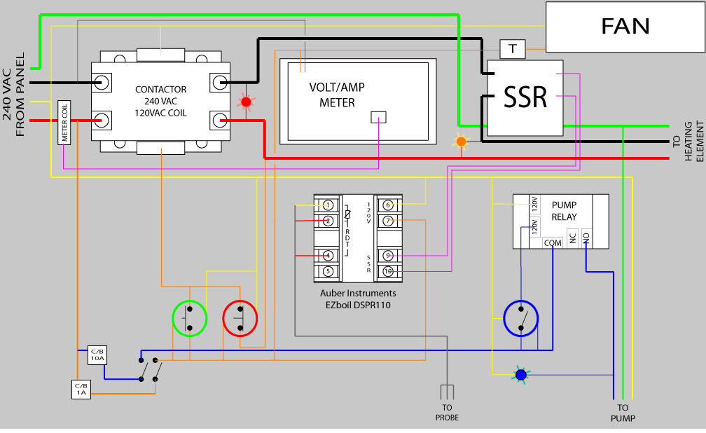
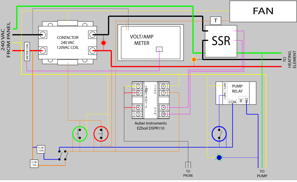
Here's the first rough of my wiring diagram....

Once I get the heat sink and SSR, I can plan exactly where everything can fit, and the decide what I can use to make an enclosure.... Thinking about just gluing up some polycarbonate, and getting some of that two color, dual layer plastic where you carve away the top color to reveal the second color, and then I can just engrave all the labels/IDs in it..

Then put it all in a nice wooden box...

EBIAB controller layout 1a wiring diagram.jpg
 
Just realized that since I changed the background color to grey, there's no point in not coloring the neutral white like it's supposed to be.. :)

The two switches in the lower left (just after the Circuit Breakers) are part of a 3 position switch.. to the left is off-off... To the center is on-off (pump circuit enabled only), to the right is on-on (pump and heater circuits on)..

The large green circle is a momentary NO push button switch with a lit green ring around it... Pushing it causes the contactor to energize which has a latch circuit on the load side through the large red switch which is a momentary NC switch with a lit red light ring around the button... Pushing it opens the latch circuit and opens the contactor, removing the 240v from the SSR... a red indicator light lights to indicate that 240v is available to the SSR... An Amber light is across the load side of the SSR to show when the heater element is actually being powered...

The large blue circle is a held NO switch that energizes the relay which puts power to the pump.. It lights a blue panel light to verify that power is going out to the pump..

EBIAB controller layout 1a wiring diagram.jpg


EBIAB controller layout 1b wiring diagram.jpg
 
Damn, uploaded the same image again, tried to delete the first one, can't find any way to do that.. Tried to delete the whole post, couldn't find any way to do that either..

There's no way to delete a post or delete a picture from a post?
 
Why are you going to the trouble of using a relay for the pump? Why not just switch power to it directly, and use the light in the switch to show that the pump is powered?

I don't see any real errors in the design.

Brew on :mug:
 
Why are you going to the trouble of using a relay for the pump? Why not just switch power to it directly, and use the light in the switch to show that the pump is powered?

I don't see any real errors in the design.

Brew on :mug:

Cuz the switch I'm using is not rated for that kind of current.. and I want it to match the other switches... Hoping to add a little 'sexy' to the whole deal... I may fail, but Imma try.. ;)
 
Cuz the switch I'm using is not rated for that kind of current.. and I want it to match the other switches... Hoping to add a little 'sexy' to the whole deal... I may fail, but Imma try.. ;)

OK, I understand the method to your madness now. Carry on.

Brew on :mug:
 
Cool! Just received my stuff from BrewHardware..

So, now I gotta think about actually doing some work on things.. ;)
 
Started a new thread for the actual build process.. People like pictures and there's not a lot of that in this thread... Plus, this is a generally boring thread to read...

New thread is HERE
 
Back
Top