You need another part http://www.drillspot.com/products/50305/White_Rodgers_PG9A38JTL24_Pilot_Burner_Generator. This will be the valve power source that would be wired through the PID controller to the gas valve. The PID controller still needs it's own power source though.
You are using an out of date browser. It may not display this or other websites correctly.
You should upgrade or use an alternative browser.
You should upgrade or use an alternative browser.
Gas and Temperature Control for Dummies
- Thread starter Sawdustguy
- Start date

Help Support Homebrew Talk - Beer, Wine, Mead, & Cider Brewing Discussion Forum:
This site may earn a commission from merchant affiliate
links, including eBay, Amazon, and others.
Regarding the Omega's, I bought a lot of 10 of them from eBay and I got a damned good deal. I like the Omega line in general, and since I already had a pH controller as well, I also wanted to stay with Omega for the... uh oh... aesthetic value! ")
I'm a bit surprised at the incompatibility of the pilot burner and thermocouple, as the place I bought the items from was in this business as a wholesaler/retailer and didn't flinch when I told him my application and that they needed to work together.
The 0.75V signal is what I'm worried about... I'll have 110V AC power provided to the system just to power the PIDs, so I guess I need to figure out how to get the AC converted to a DC (e.g., a standard transformer, of which I probably have a hundred spares laying around the house that bring 110V AC down to 4.5 - 12 V DC). Any thoughts on which resisters and how to hook them up?
Sorry, I'm a biologist, not an electrician, but still love to play with the gadgets!!
Thanks for the quick reply!
OP
OP
Sawdustguy
Well-Known Member
Regarding the Omega's, I bought a lot of 10 of them from eBay and I got a damned good deal. I like the Omega line in general, and since I already had a pH controller as well, I also wanted to stay with Omega for the... uh oh... aesthetic value!
I'm a bit surprised at the incompatibility of the pilot burner and thermocouple, as the place I bought the items from was in this business as a wholesaler/retailer and didn't flinch when I told him my application and that they needed to work together.
The 0.75V signal is what I'm worried about... I'll have 110V AC power provided to the system just to power the PIDs, so I guess I need to figure out how to get the AC converted to a DC (e.g., a standard transformer, of which I probably have a hundred spares laying around the house that bring 110V AC down to 4.5 - 12 V DC). Any thoughts on which resisters and how to hook them up?
Sorry, I'm a biologist, not an electrician, but still love to play with the gadgets!!
Thanks for the quick reply!
It's simple, get a 5 volt DC Wall Wart and a 1000 ohm 1/4 watt resistor (R1) and a 175 ohm 1/4 watt resistor (R2) and you have it.

http://www.sparkfun.com/products/8269
Sawdustguy,
OK, I'm continuing to circle this bad boy... and I'm threatening to jump in with both feet... flailing!!
In a bit of frustration, I just RETURNED everything that I bought ('cept the PIDs) and I'm starting fresh. I'm going with the Honeywell VR8200A Super Tradeline model that comes with a Honeywell Q340A thermocouple, the Honeywell Q314A4584 pilot burners, and the Honeywell AT72D1683 24V transformers.
But now I'm hung up on a couple of other things...
1) In the EXCELLENT drawing provided in this thread showing the Auber Instruments SLY-4352 and the Honeywell VR8200A, the 24V transformer is incorporated into the system using terminals 6 & 7 of the Auber SLY-4352. When I look at the Instruction Manual for the SYL-4352 that I downloaded from their website, it shows terminals 7 & 8 are used by the aforementioned un-needed SSR, with terminal 6 not being used at all. The only places in the manual that shows terminal 6 ever being used is in association with the Auber SLY-4342. Was this just a typo in the drawing, or is this an undocumented feature of the Auber SLY-4352?
2) Among the Omega CN9000As that I have, most of them appear to be pretty similar to one or the other of the two Aubers - the Omega CN9111A has relay contact outputs for both output 1 and output 2 (like the 4342), and the Omega CN9121A and CN9122A both have SSR 5V DC pulse outputs (similar to the 4352's SSR 12V DC pulse). My question here is, can I use the relay contact method used by the Auber SLY-4342 just as easily as the SSR method used by the SLY-4352, or should I stay with the SSR outputs? Is there a difference between the 5V and 12V DC pulses, or will both have the same effect on the valve?
I guess if I were to try and figure out where my ignorance in all of this lies, it comes from not really knowing what the gas control is expecting as a "signal" telling it to open. Is it simply the closure of the 24V electrical circuit that allows the transformer to then open the valve, or is there actually a DC "signal" (5V or 12V) being received by the gas valve that then tells it to open the the valve by using the power provided by the transformer... if even any of THAT description makes any sense.
Yeah... most definately a newbie... soon to be wannabie... soon able to sound like an expert...
OK, I think I just had one of those ever-more-common AH HA moments...
The gas valve is dumb - all it's waiting for is an electrical charge from the transformer to "tell" it to open the valve. The power to the transformer is controlled by the relay in the PID. That would seem to make sense!!
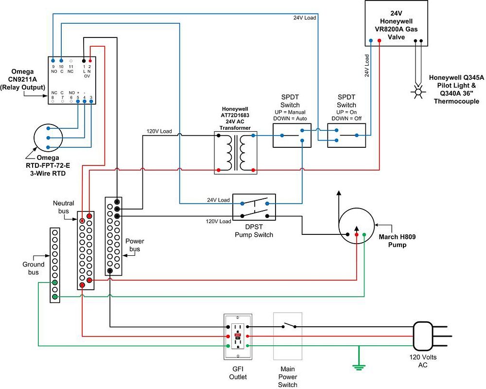
Assuming that to be the case, here is my wiring schematic for ONE of the PID/gas valves. I plan to eventually have two gas valves hooked up this way, plus another 6-8 PIDs being used just to monitor temps at various parts of the system - hence the use of power buses to distribute power. I also wanted to be able to bypass the PID and operate the burner on manual, hence the use of 3-way switches.
http://i366.photobucket.com/albums/oo109/NamakoH3/BrewStandElectronics.jpg
Any thoughts? Any fatal flaws to consider before I fry one or more of my PIDs?
Thanks all!!
Namako
The gas valve is dumb - all it's waiting for is an electrical charge from the transformer to "tell" it to open the valve. The power to the transformer is controlled by the relay in the PID. That would seem to make sense!!
Assuming that to be the case, here is my wiring schematic for ONE of the PID/gas valves. I plan to eventually have two gas valves hooked up this way, plus another 6-8 PIDs being used just to monitor temps at various parts of the system - hence the use of power buses to distribute power. I also wanted to be able to bypass the PID and operate the burner on manual, hence the use of 3-way switches.
http://i366.photobucket.com/albums/oo109/NamakoH3/BrewStandElectronics.jpg
Any thoughts? Any fatal flaws to consider before I fry one or more of my PIDs?
Thanks all!!
Namako
OP
OP
Sawdustguy
Well-Known Member
Sorry I did not get to answer you sooner. See my comments in RED below.
The gas valve is dumb - all it's waiting for is an electrical charge from the transformer to "tell" it to open the valve. The power to the transformer is controlled by the relay in the PID. That would seem to make sense!!
The above is exactly correct except I would control the output of the transformer.
Assuming that to be the case, here is my wiring schematic for ONE of the PID/gas valves. I plan to eventually have two gas valves hooked up this way, plus another 6-8 PIDs being used just to monitor temps at various parts of the system - hence the use of power buses to distribute power. I also wanted to be able to bypass the PID and operate the burner on manual, hence the use of 3-way switches.
http://i366.photobucket.com/albums/oo109/NamakoH3/BrewStandElectronics.jpg
Any thoughts? Any fatal flaws to consider before I fry one or more of my PIDs?
Two comments on your drawing: 1) It would be alot easier for you to control the secondary or output of the transformer. 2) Why does the pump have to be switched on for you to control the burner? The relay in your PID will never get any power to switch unless you have the pump switched on.
Namako
Thanks for the thoughts, and I'll try to justify mine
Without a constant flow passing over the RTD, the wort that would be sitting there when the pump was turned off would be cooling. It will quickly be cool enough to be telling the PID to apply heat, thereby turning on the gas valve. As a result, without a flow, the temps in the HLT will be rising, eventually to a boil. I didn't want that to happen.
I also wanted the ability to take the PID out of the equation (switch on the left) and run the gas valve manually (switch on the right), hence the ability to go "manual." For example, during cleaning, I'd rather not be playing with PID set points just to warm up some water. I'm also concerned that a suddenly-defective PID would interrupt my brew day.
As for controlling the output of the transformer... I thought about that, but I'll show my ignorance again... The PID's relay seems to be controlling AC power through those terminals (9 & 10), while the power after the transformer is DC. Since I'm "in-line" with AC power at the switches, I wanted to stay on the AC side. Am I wrong?
Here's a graphic of my proposed control panel, showing the PIDs and the switches...
http://i366.photobucket.com/albums/oo109/NamakoH3/PanelDesign.jpg
Thanks again!
Namako
OP
OP
Sawdustguy
Well-Known Member
As for controlling the output of the transformer... I thought about that, but I'll show my ignorance again... The PID's relay seems to be controlling AC power through those terminals (9 & 10), while the power after the transformer is DC. Since I'm "in-line" with AC power at the switches, I wanted to stay on the AC side. Am I wrong?
Yup. The 24 volt transformer is a device that makes a higher AC voltage in a lower AC voltage. In North America that would make 120 volts to 24 volts. The Honeywell valve can only accept AC voltage, that is why we use a transformer and not a DC power supply.
Uh oh... another "AH HA" moment so quickly arrives...
Did I mention I'm a biologist, not an electrical engineer?
So, the transformer for the gas valve is NOT like every other "transformer" that I thought I had in the house. I thought all of my other "transformers" converted AC to DC - e.g., 120/240 CAC in, 3 VDC out - but as you alluded, they're really just DC power supplies being driven by an AC current, and are NOT really "transformers" at all.
Indeed, the Honeywell AT72D-1683 24V transformer that I want to use clearly states that it steps down the voltage from 120 VAC to 20 VAC, confirming that both sides are AC, and therefore qualifies as a true transformer!!
Well, don't I feel a bit stupid, and now it's clearly documented in this thread!! ;^)
Did I mention I've been drinking homebrews as I type this stuff? No, wait - it's X'Mas morning here in Japan, and I shouldn't really use that excuse this early.
Since that's the case, I can indeed wire the PID into the circuit AFTER the transformer, and I will. That modification will keep the transformer from repeatedly cycling on and off each time the PID calls for heat, and reduce constant surges in the system.
Sawdustguy, seriously, thanks a LOT for your input!! It was incredibly valuable... and pretty damned educational to boot!
I'll modify and re-post my new wiring scheme for use in the thread.
Namako
OP
OP
Sawdustguy
Well-Known Member
I am happy to help. If you have any more questions fire away. If I can't answer I am sure others will be able to chime in. Happy Holidays!!
OK, I just finished the re-design of the wiring schematic. In light of Sawdustguy's concerns regarding the power to the pump precluding use of the gas valve, I decided to change up the switching a bit, using a DPST switch for the pump, and wiring it into the PID relay. Here's the link to the JPG...
Now, the PID and the transformer are constantly energized when the main power is on, and the pump and gas valve can be turned on with the flip of a switch.
As a result, this should allow me to use the pump anytime I want, and I can manually operate the gas valve whenever the "Manual/Auto" switch is in the "Manual" position. When the switch is in the "Auto" position, however, the pump will need to be turned on, and as long as the ball valves are open, it will be pumping ambient temperature wort past the RTD that is used by the PID to drive the gas valve.
Again, this is just a safety measure to ensure that the HLT isn't being heated up to boiling because the liquid that is in contact with the RTD has cooled and the PID erroneously thinks that it needs to be heated back up to the set point, when in fact, the HLT is already at the proper temp.
Any thoughts, suggestions, warnings, criticisms, even laughter, is appreciated... usually.
Namako
OP
OP
Sawdustguy
Well-Known Member
Without a constant flow passing over the RTD, the wort that would be sitting there when the pump was turned off would be cooling. It will quickly be cool enough to be telling the PID to apply heat, thereby turning on the gas valve. As a result, without a flow, the temps in the HLT will be rising, eventually to a boil. I didn't want that to happen.
Your diagram looks fine but you are still running the pump while heating the water in your HLT. This I do not understand. Does the pump really need to be on while heating strike or sparge water? Your PID temperature sensor should be in the HLT where you can actually read the temperature of what you are heating. Maybe I am not seeing what you are trying to accomplish. Maybe an over all diagram of your brewery would help explain things.
Ah, you want LOGIC??? Sorry, it's the day after X'Mas, and all through the house is... CHAOS!!
The RTD (temperature probe) that drives the HLT PID is in-line as the water comes up from the pump and into the distribution manifold, not sitting in the HLT - I only monitor the temp in the HLT out of curiosity and boredom. I'm measuring the temperature of the HLT water after the pump has recirculated it through most of the piping. Once I've reached my desired strike/sparge temperature at near the outlet, I flip the ball valve and instead of returning the water to the HLT, I deliver the water - at the right temp - to the mash tun, whether I'm just striking in or I'm now sparging.
I plan on using the same logic as I recirculate wort during the mash, with the RTD that drives the Mash Tun PID also being in-line, just as it exits the heat exchanger and returns to the mash (the outlet). In my case, I don't have a direct-fired MT, so I have my wort being pumped through an immersion chiller sitting in the boil kettle (yes, I use BOTH during the strike/mash), with the MT PID driving the gas valve under that burner.
Once I'm nearly done with the mash (about 10 minutes prior to sparging, after full conversion), I stop the mash recirculation, remove the heat exchanger from the boil kettle, and then pump the water in the boil kettle over to the HLT - that takes about 5 minutes - and the HLT PID takes over, getting the water ready for the sparge.
I will eventually put a burner under the mash tun and use the MT PID to drive that burner (Brew Sculpture 2.0), again measuring the wort temp just prior to it returning to the mash. Because of the amount of SS piping I have in my brew stand (see link below for picture), my system has an inherent heat loss that I need to account for, hence the use of in-line measurement. If I just measure the temp in the HLT, for example, by the time the water makes it through the system, it has already cooled.
Here's my brew sculpture:
http://i366.photobucket.com/albums/oo109/NamakoH3/DSCN5161.jpg
and
http://i366.photobucket.com/albums/oo109/NamakoH3/DSCN5169.jpg
I don't really care what temperature the water is in the HLT, just as long as it is the right temperature when it reaches the end of the line and re-enters the HLT or enters the mash tun. The PID will know (or rather, will "learn") what temperature that needs to be, and make it so.
That keeps me from having to worry about the thermal mass of my system, both the inherent properties based on the equipment itself, AND the variations caused by the seasonality of my brewing. I brew in air temperatures ranging from at or below freezing to near 100 degrees F, and that changes the thermal properties as well. By measuring my temps at the outlet, rather than the source, I really don't need to care what happens "behind the curtain."
Back to the chaos...
As requested, here's a schematic of my brew system...
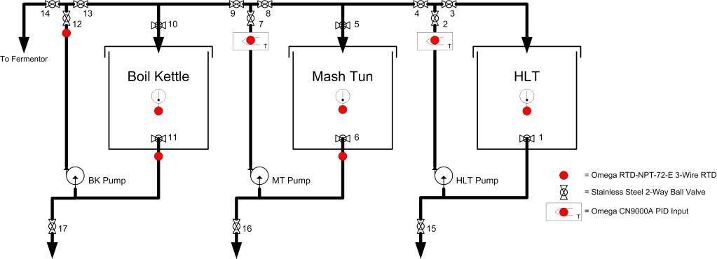
Depending on which valve is open, I can move water and wort from any kettle to any other kettle. I can also set the valves and allow PBW to cycle through the system virtually forever (HLT --> MT --> BK --> HLT)
If anyone has any questions, I'm happy to defend/change.
Depending on which valve is open, I can move water and wort from any kettle to any other kettle. I can also set the valves and allow PBW to cycle through the system virtually forever (HLT --> MT --> BK --> HLT)
If anyone has any questions, I'm happy to defend/change.
OP
OP
Sawdustguy
Well-Known Member
Ah, you want LOGIC??? Sorry, it's the day after X'Mas, and all through the house is... CHAOS!!
The RTD (temperature probe) that drives the HLT PID is in-line as the water comes up from the pump and into the distribution manifold, not sitting in the HLT - I only monitor the temp in the HLT out of curiosity and boredom. I'm measuring the temperature of the HLT water after the pump has recirculated it through most of the piping. Once I've reached my desired strike/sparge temperature at near the outlet, I flip the ball valve and instead of returning the water to the HLT, I deliver the water - at the right temp - to the mash tun, whether I'm just striking in or I'm now sparging.
I plan on using the same logic as I recirculate wort during the mash, with the RTD that drives the Mash Tun PID also being in-line, just as it exits the heat exchanger and returns to the mash (the outlet). In my case, I don't have a direct-fired MT, so I have my wort being pumped through an immersion chiller sitting in the boil kettle (yes, I use BOTH during the strike/mash), with the MT PID driving the gas valve under that burner.
Once I'm nearly done with the mash (about 10 minutes prior to sparging, after full conversion), I stop the mash recirculation, remove the heat exchanger from the boil kettle, and then pump the water in the boil kettle over to the HLT - that takes about 5 minutes - and the HLT PID takes over, getting the water ready for the sparge.
I will eventually put a burner under the mash tun and use the MT PID to drive that burner (Brew Sculpture 2.0), again measuring the wort temp just prior to it returning to the mash. Because of the amount of SS piping I have in my brew stand (see link below for picture), my system has an inherent heat loss that I need to account for, hence the use of in-line measurement. If I just measure the temp in the HLT, for example, by the time the water makes it through the system, it has already cooled.
Here's my brew sculpture:
http://i366.photobucket.com/albums/oo109/NamakoH3/DSCN5161.jpg
and
http://i366.photobucket.com/albums/oo109/NamakoH3/DSCN5169.jpg
I don't really care what temperature the water is in the HLT, just as long as it is the right temperature when it reaches the end of the line and re-enters the HLT or enters the mash tun. The PID will know (or rather, will "learn") what temperature that needs to be, and make it so.
That keeps me from having to worry about the thermal mass of my system, both the inherent properties based on the equipment itself, AND the variations caused by the seasonality of my brewing. I brew in air temperatures ranging from at or below freezing to near 100 degrees F, and that changes the thermal properties as well. By measuring my temps at the outlet, rather than the source, I really don't need to care what happens "behind the curtain."
Back to the chaos...
I think, because of the way a PID works you are going to have a difficult time regulating the temperature of the HLT water the way you propose to do it. Maybe someone like CodeRage who has a much better knowlege of PID's will chime in on this.
I think, because of the way a PID works you are going to have a difficult time regulating the temperature of the HLT water the way you propose to do it. Maybe someone like CodeRage who has a much better knowlege of PID's will chime in on this.
My understanding... and I've been proven wrong even in THIS very thread - is that one of the advantages of using a PID (vice a simple on-off controller) is that it is able to "learn" to compensate for the lag in both the response time and the rate of increase that occurs between the initial call for heat (based on the PID set-point) and the final realization of achieving the set-point temp.
If I place the RTD way back in the HLT, then all I'm doing is keeping the HLT at a set temperature, and that's really not the point. I want to deliver water to the mash at a specific temperature, AFTER it has had the chance to flow through - and cools down in - my system, regardless of whatever the HLT temperature needs to be in order to deliver that temperature at the outlet.
Maybe I'm giving the PID more credit than it deserves... I'd like to hear from others who have tried moving the RTD around in their system.
butterball1121
Member
This thread has been extremely informative and enlightening...
That said, how easy would it be to make the application to other common valve/contoller/pilot combinations?
A friend of mine is in the HVAC business and throws away two furnaces a week. He hung on to one for me and im wondering if its worth figuring out the nuances of controlling it when there is a such a straight forward thread like this for different components.
Its hard to turn down a whole working furnace...seems like there would be all sorts of goodies to salvage (valve, pilot, TX, spark igniter, relays, switches, CB)
Coincidentally:
-White Rodgers 36E series valve
-3 wire pilot
-120/24 VAC TX
-working PCB
Bryce
Active Member
Sawdustguy I know this is an old post but I wanted to see if you had a wiring diagram of your old control panel maybe some inside pics of it. I would love to make this control box. I have to say thanks also as your articles have been KEY!!! In my single tier build. Are you using an asco value as an emergency shutoff for your HLT gas?
THANK YOU!!!
THANK YOU!!!
Hey all! This thread is old, but it seems like a good place to post this.
I found a supplier in China for SS 1/2 NPT electric (12VDC) ball valves. Only $24 each plus shipping and wire transfer fee (which is a bit much). If anybody else is interested, we could save some $$ on shipping and wire fee. Drop me a line. I plan on making the purchase on Monday.
I found a supplier in China for SS 1/2 NPT electric (12VDC) ball valves. Only $24 each plus shipping and wire transfer fee (which is a bit much). If anybody else is interested, we could save some $$ on shipping and wire fee. Drop me a line. I plan on making the purchase on Monday.
OP
OP
Sawdustguy
Well-Known Member
Hey all! This thread is old, but it seems like a good place to post this.
I found a supplier in China for SS 1/2 NPT electric (12VDC) ball valves. Only $24 each plus shipping and wire transfer fee (which is a bit much). If anybody else is interested, we could save some $$ on shipping and wire fee. Drop me a line. I plan on making the purchase on Monday.
These valves are not a great choice for propane. You really want a standing pilot furnace valve with safety shutoff especially if you anticipate brewing outdoors. You see, propane is heavier than air and does not dissipate in the air like natural gas. Propane also has a 270 to 1 expansion rate from liquid to gas. That means 1 gallon of liquid propane in a tank becomes 270 gallons of propane in gas form when removed from the pressure of the tank. The flame does not have to out for very long before a lot of gas has been released making for a very dangerous situation.
These valves are not a great choice for propane. You really want a standing pilot furnace valve with safety shutoff especially if you anticipate brewing outdoors. You see, propane is heavier than air and does not dissipate in the air like natural gas. Propane also has a 270 to 1 expansion rate from liquid to gas. That means 1 gallon of liquid propane in a tank becomes 270 gallons of propane in gas form when removed from the pressure of the tank. The flame does not have to out for very long before a lot of gas has been released making for a very dangerous situation.
No, I wouldn't use these for propane. Only liquid.
OP
OP
Sawdustguy
Well-Known Member
No, I wouldn't use these for propane. Only liquid.
I figured that what you proposed since this is a thread about controlling gas with a solenoid valve. I see you are a Newbie but you should have posted in the Group Buy section.
TimWeber
Well-Known Member
I just installed one of these on my rig. THANK YOU SAWDUSTGUY for all of the info!
I'm running LP, I have a regulator going in the the valve (0.5 lbs), I changed out the orifice in the valve and the one in the pilot light, all connections seem correct, the valve is set to the on position, I even turned the pilot light adjustment screw counter clockwise a few times.
I've been scratching my head for a few hours now. I activate the controller, the spark generator starts to fire but no gas....
Any suggestions on what I could have done wrong? Would pictures help?
Thanks for any help!
Until the pilot burner lights it will remain in spark mode as the flame is needed to complete the circuit. Usually it will take a couple tries to get the air out of the system before the pilot lights up, after that it is almost instant light up so do not give up yet.
TimWeber
Well-Known Member
Klaude, I just let it go until the controller turned off :-(
I just realized that my regulator is .5 psi...is this correct?
I just realized that my regulator is .5 psi...is this correct?
The regulator pressure is okay, you just have a lot of trapped air relative to the low volume of the pilot burner. Cycle the ignition until pilot lights, might take 5-10 times first time. You might try a butane match flame across pilot burner to simulate flame so ignition will not time out, leave selector knob on honeywell valve in pilot position while you get air out and pilot burning so main burner will not light off unexpectedly.
TimWeber
Well-Known Member
I have a feeling the regulator is busted.
I removed the valve, no gas was coming out of the regulator. Looks like there is a Nat/LP button that you can flip. I poked my finger in where the spring was and gas jetted out. Now I think its either damaged or I received it damaged. Damn ebay.
Anyone know where I can get a .5psi LP regulator with 1/2" F threads?
if the regulator pressure is too high ( > 1/2PSI) the gas valve valve locks shut as a safety feature, back the low pressure regulator off and try again. If the valve was purchased as a NG valve then there is a spring that needs replacing in the valve internal pressure regulator so the outlet pressure can be turned up from 1/6'th to 1/2 PSI. This is a quick change using a flat blade screwdriver, remove cover, unscrew retainer, exchange springs, and reassemble. After burner is fired, open valve to burner wide open and adjust regulator spring for max fire level you want to run, it will be easier to throttle flame afterwards.
SPLASTiK
Well-Known Member
Dummy here... A little different than other threads which seem to only talk about Aubers and Love controllers but this thread is commonly referenced so it might lead others with this question (well, I think most will buy those since they're about the same price and have more info) I'm hoping someone can assist me.
Anyways, I've got an unwired 120V Johnson A419 laying around I'd like to to use to control a Honeywell valve withstanding pilot on my MLT. I've wired an A419 for use with a freezer before... but I've been reading all the threads, looking up terms and I'm probably overthinking things and I'm still left scratching my head.
Quick link to A419 wiring diagram for reference.
My Parts List:
I'm probably far off here on this modified Sawdustguy diagram... but is this correct?

Bueller? Thanks everyone for your help.
Anyways, I've got an unwired 120V Johnson A419 laying around I'd like to to use to control a Honeywell valve withstanding pilot on my MLT. I've wired an A419 for use with a freezer before... but I've been reading all the threads, looking up terms and I'm probably overthinking things and I'm still left scratching my head.
Quick link to A419 wiring diagram for reference.
My Parts List:
Plus the A419, obviously.The gas control part numbers to look for are:
Honeywell VR8200 valve http://www.pexsupply.com/Honeywell-VR8200A2132-1-2-24-Vac-Standing-Pilot-Gas-Valve-11588000-p
Honeywell Q314 pilot burner http://www.pexsupply.com/Honeywell-Q314A4586-Honeywell-Q314A4586-Pilot-Burner-4113000-p
Honeywell Q390 Thermocouple http://www.pexsupply.com/Honeywell-Q390A1046-24-Thermocouple-1721000-p
75 VA transformer http://www.pexsupply.com/Honeywell-...Transformer-w-9-in-Lead-Wires-75VA-11016000-p
I'm probably far off here on this modified Sawdustguy diagram... but is this correct?
Bueller? Thanks everyone for your help.
ClaudiusB
Well-Known Member
i'm probably far off here on this modified sawdustguy diagram... But is this correct?

bueller? Thanks everyone for your help.
Non of the secondary xfrm wires should be connected to 120V as in your drawing.
Your wiring is supplying 120V to the valve.
1. Remove wire 120 from TB1 & TB2 C
2. Remove wire R from from AC Com TB1
3. Connect wire R from XFRM to TB2 C
4. Have fun with your set-up
Cheers,
ClaudiusB
SPLASTiK
Well-Known Member
That makes too much sense.Non of the secondary xfrm wires should be connected to 120V as in your drawing.
Thanks a bunch!
RonRock said:I test fired one of my burners today. Was able to make fire, but a couple questions.
I plan to interface with my BCS controller. The BCS has 6 outputs-
"Discrete Outputs (Outs) are rated at 5VDC up to 20mA each. The BCS-460 is designed to control relays, and not to drive high current loads." (BCS Wiki)
Any suggestions how to make this work?
The ignition module as I have wired currently (test phase) ignites pilot when powered up and burner lights. Seems to work properly. I have wired as in post #1 in this thread. With the exception (Since I'm not use'ng a PID) I have 1 24v wire going to 24v Gnd, other 24v wire going to TH-W. From what I have read with the instructions the TH-W is the thermostat (switched) wire. If I break that wire of course power is lost and valve is shut down. So, should I run 24v transformer wires to 24v Gnd / 24v? Splice off 24V for Thermostat power (BCS)?
Sorry to resurrect an old thread, but did any of you guys controlling these valves with the bcs ever get things working how you wanted? I am fixing to start my build and am trying to decide between bcs and pid's. From the wiring diagrams posted, I just wire the ssr's in like a pid if I decide to go with the bcs...right????
AtomicGecko
Member
Anyone ever use a Carrier Pilot Ignition Control Module LH33CM600. Found this model ebay was a little cheaper on average compared to the Honeywell.
- Joined
- Apr 23, 2008
- Messages
- 356
- Reaction score
- 4
Sorry if I missed it but I see the kits listed as Y8610 U 3003, Y8610 U 4001 and Y8610 U 6006. Does anyone know the differences between these?
atoyot
Well-Known Member
Here ya go.
Honeywell Y8610U 4001 retrofit kit for natural or LP gas, up to 150,000 BTU, converts standing pilot systems to intermittent pilot systems;
replaces Y8610F 5003
Honeywell Y8610U 6006 retrofit kit for natural or LP gas, up to 270,000 BTU, converts standing pilot systems to intermittent pilot systems;
replaces Y8610U 3003
- Joined
- Apr 23, 2008
- Messages
- 356
- Reaction score
- 4
ah, it is all in the BTU's. Thanks dude.
- Joined
- Apr 23, 2008
- Messages
- 356
- Reaction score
- 4
Does anyone know what the banjo BG14 typically runs at
BTU's wise? I think it is rated for about 210,000 BTUs but could one get buy with a 150,000 BTU rated valve?
BTU's wise? I think it is rated for about 210,000 BTUs but could one get buy with a 150,000 BTU rated valve?
BG14 on low pressure propane is nominally 80K btu's, more than that amount of fire under a keg is a waste of time other than burning valve handles and thermometers up.
Sawdustguy said:This is my second thread designed to help those who may be building a new brewery. I was asked some of these questions recently and decided it would be handy information to have documented on the forum. Again, before I get flamed, I am not insinuating anyone reading this forum or post is a dummy.
The system below utilizes a Honeywell Y8610U intermittent pilot propane or natural gas valve kit (Intermittent Pilot Retrofit Kit). I feel this method may be a touch safer than the Brutus 10 method because there is no concearn over your pilot blowing out.
The Y8610U includes the following features:
• Y8610U kits can be used with either natural or LP gas.
• Y8610U provides a 90 second maximum ignition trial, shuts off, waits six minutes nominal, then reinitiates the pilot ignition sequence. The ignition trial, shutoff, and wait cycle repeat until the pilot lights or the call for heat ends.
• Y8610U kits can be used with either natural or LP gas; it provides timed trial for ignition and 100 percent pilot shutoff on loss of flame.
Each Y8610U kit includes:
— S8610U Intermittent Pilot Module.
— VR8304M Dual Valve Combination Gas Control.
— 392431 Igniter-Sensor* (Not used for this Application you will need to purchase a Q345A1313. See Below).
— 394800-30 Ignition Cable.
— 393691 Natural to LP Gas Conversion Kit.
— Wiring Harness.
— 393690-14 Straight Flange Kit (3/4 in.) .
— Reducer adapters for gas control.
— Adhesive mounting option for S8610.
— Installation hardware.
You will also need a Pilot Burner and Orifice.
— Q345A1313 Pilot Burner/Sensor Assembly.
— 390868-1 0.010" Orifice for Q345A1313.
The diagram below describes a low pressure propane system designed to control the temperature of a HLT. It can be used to control the temperature of any of the three vessels in your brewery. IMPORTANT: This system is designed for low pressure propane or Natural Gas. If using Propane, please make sure your propane regulator is set for 11 WC or less than 0.5 lbs pressure. Please make sure you read and understand the instructions accompanying the Y8610U kit from Honeywell before proceding. The information presented in this post can be found in that document also.
The Y8610U can be purchased from Patriot Supply. Their Ebay Store is (Patriot Supply Ebay Store).
The SYL4352 and Thermocouple can be purchased from Auber Instruments. Their URL is (Auber Instruments Website).
Maybe I missed this, but does the Y8610U kit come with the valve itself, or just the components to convert an existing valve to intermittent pilot? Great thread but all the part numbers have me a little overwhelmed
The VR8304M Dual Valve Combination Gas Control is the gas control valve in this package
Similar threads
- Replies
- 0
- Views
- 553
- Replies
- 0
- Views
- 723
- Replies
- 1
- Views
- 920