Electric Question

Homebrew Talk - Beer, Wine, Mead, & Cider Brewing Discussion Forum

Help Support Homebrew Talk - Beer, Wine, Mead, & Cider Brewing Discussion Forum:

This site may earn a commission from merchant affiliate links, including eBay, Amazon, and others.
Wow Ed...that wiring one help me visualize this a ton.

I noticed you changed the PB LED from the relay contact to the Coil Contact...was that just an AWG issue? I was worried about that myself.


I did some pricing today and you are totally correct...50a is for me, selector here I come <Glad I saved the file> :)
 
Ohio-Ed,
I think I'm going to be basing my system off of yours.
Two questions/favors if you don't mind.
1. Is there any way I can get the visio docs so I don't have to start from scratch.
2. Any chance you're going to have a parts list in the future.

Between this thread and the Pol's original HERMS thread, I've learned a lot over the past several months.
 
Wow Ed...that wiring one help me visualize this a ton.

I noticed you changed the PB LED from the relay contact to the Coil Contact...was that just an AWG issue? I was worried about that myself.


I did some pricing today and you are totally correct...50a is for me, selector here I come <Glad I saved the file> :)

I wired the PB LED from the coil of the contactor purely out of convenience. Its a little shorter/easier path to run the wire.

I think its a lot easier to lay it out on paper before you start putting holes in the box / panel. I got all the power wired on my temporary panel tonight... now just need to wire the control lines.

Ed
 
Ohio-Ed,
I think I'm going to be basing my system off of yours.
Two questions/favors if you don't mind.
1. Is there any way I can get the visio docs so I don't have to start from scratch.
2. Any chance you're going to have a parts list in the future.

Between this thread and the Pol's original HERMS thread, I've learned a lot over the past several months.


I might do a parts list, but it may be a while yet. I still have to wait to see what I actually end up using.

Here is a link to the Visio files:

http://www.mediafire.com/file/w52yyy3l3md/Panel v5.1 Wiring v1.5.vsd

http://www.mediafire.com/file/gvgwlxelymc/Panel v5.1.vsd

Ed
 
Thanks, saved me a ton of time 'rebuilding the wheel'.
Still accumulating funds, so I'm pretty far from needing a parts list anyway :).
 
Sorry to be a pain, but both of those docs link to the wiring diagram.

Beautiful work btw! Can't wait to see the finished product. Do you have an ETA at this point?

Eric
 
Sorry to be a pain, but both of those docs link to the wiring diagram.

Beautiful work btw! Can't wait to see the finished product. Do you have an ETA at this point?

Eric

The file links should be fixed now... let me know if you still have any problems.

Thanks for the complement. Yea, I can hardly wait to see the finish product too.

I'm having a bunch of guys over to brew on the 20th. I plan to use the "temporary setup" for the 20th. The temporary setup consists of a plywood backplane and a spaghetti plate of wires. I can already tell I'm gonna have to move some components around a bit for the final version... because of the size of the wires, some of the "wiring channels" need to be adjusted (10 gauge wire doesn't make 90 degree bends).

Ed
 
Thanks.
You'll have to post before and after pics of the setup.
I'm pretty excited to get started, but have to wait for my Uncle Sam to give me some money for the project.
 
IT"S ALIVE!!!!

Got the control wiring in place and the temporary panel & wiring works as expected!!!

I will post some pictures when I have a bit of time... You know what a PITA it is to take/re-size/host & link pics... just don't have time right now.

Ed
 
Got a few pics of the TEMPORARY setup...

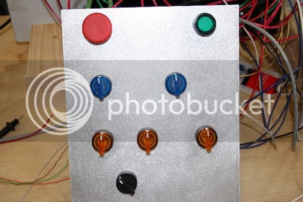
Here is the temporary panel... I just punched some holes in a piece of aluminum and then used a random orbit sander to kind of etch the face before I mounted the switches. I plan to brew with this so I will likely make some temp labels. As you can see, I laid it out like CodeRage suggested... I like it, but think for the final version I may have to move the Heat switches up a row to keep them from hitting components in my slant top box.

IMG_3262a.jpg


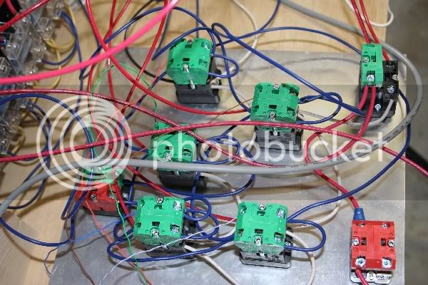
Back side of the panel... plate of spaghetti:
IMG_3265a.jpg


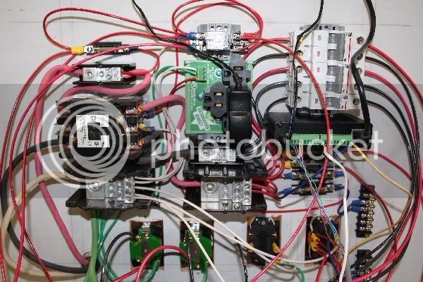
This is the temporary back plane... this is what would be on the bottom of the box. Every thing down to the receptacles, will be mounted on a panel. The BCS-460 is mounted on a DIN clip (you can see it on the right hand side). I REALLY hate the BCS-460 power supply (wall wort), you can see I have a DIN mount receptacle in the middle of the panel (takes up way more space than I'd like, actually more space that the BCS-460 itself).
IMG_3263a.jpg


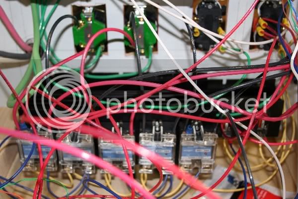
Hard to see through this mess of wires but here is the SSRs and heat sinks. I'm going to mount the SSRs to one side of an aluminum plate and the heat sink to the other and mount the plate to the box with the SSRs on the inside.
IMG_3264a.jpg
 
Congrats! Glad to see its coming together for you :)

I have a BCS and I am in need of a panel mount 120v receptacle like that... may I ask what is the model and where did you find it? The ones I've found are pretty expensive.

Thanks
 
Nice try :p

The BCS requires 6VDC-10VDC. The one you linked is 5.0-5.2VDC. The next model up is 12VDC. Misses on either end. :(

Criminey!

Eccsynd, you guys really need to put some kind of switching power supply that will take 12VDC. You've got enough heat sink mass in the case to use a 7805 linear reg for that matter.

I wonder if you could take that 5V power supply and wire it to the Accessory 5V instead of the typical power supply in. If the acc 5v is fuse protected inside than maybe not. The idea is that you can backfeed the 5v through the system with out have to go through their LDO PS.

Maybe some one from their group can comment.
 
Looks good man, with all of that wire aren't you glad you had a drawing ;)

The BCS power supply, you could go with something like this.
http://www.automationdirect.com/adc...Plastic_Low_Profile_Case_(Class_2)/PSC-05-012.

The wallwort will work but if it bugs you enough you have options :).

The drawing was a godsend... it took me a while to convert from the "logical" drawing to the "physical" drawing, but then the actual wiring went like clock work. Thank you for all your help on this!

I do have a question for you... what type wire can/should I use? Most of the wire is currently stranded thhn, but it's very stiff. I originally had a couple pieces of #6 thhn (left over from wiring the GFCI) that I used to connect the contactor to the terminal blocks and it was a huge PITA. I striped the SOOW cord back and used those conductors which was much easier to work with. So, for the rest of the panel, do I NEED thhn or is there something easier to work with I can/should use?

I will have an extra outlet on the receptacle controlling the RIMs heater... I'm thinking of making the on outlet unswitched and taking the BCS "wall wort" out of the box and plugging it in externally and then just run the power jack through a hole in the bottom of the box. That would get the wall wort and the DIN mount receptacle out of the panel. That would free up some space, but certainly not be what I was hoping for.

I looked all over for a power supply, other than wall worts, I had a hard time locating one that didn't cost an arm & a leg.

Ed
 
I do have a question for you... what type wire can/should I use? Most of the wire is currently stranded thhn, but it's very stiff.
Ed

i've got stranded THHN in mine now, and planned to use it on the new control panel. if you get any feedback outside of this thread, please post what you find out. i'd love to find something easier to work with as well.

p.d.
 
Ohio-Ed:
Your build is coming together quite nicely!
Theoretical question: Shouldn't you run 6 awg wire from the distribution blocks to the 30 amp breakers and then step down to 10 awg after the breaker?
 
That sucks...at least from my perspective.

Probably a good time to verify: the Auberin PID's don't work like that do they?

Nope... Auber PID's have no power supply. You direct wire them. But I "think" they are available in other than just 120v, so be careful when you order.
 
Ohio-Ed:
Your build is coming together quite nicely!
Theoretical question: Shouldn't you run 6 awg wire from the distribution blocks to the 30 amp breakers and then step down to 10 awg after the breaker?

Thank You...

Well... I guess theoreticlly probably yes... But I think it would only be an issue if there were a short in the panel between the terminal block and the breaker. But then If I followed that theory, I should run 6awg to every fuse, not just the 30amp breakers.
 
Nope... Auber PID's have no power supply. You direct wire them. But I "think" they are available in other than just 120v, so be careful when you order.

You can also get them in 12v and 24v dc. I think they are labeled smoker temp controllers. I got one in 12v
 
Thank You...

Well... I guess theoreticlly probably yes... But I think it would only be an issue if there were a short in the panel between the terminal block and the breaker. But then If I followed that theory, I should run 6awg to every fuse, not just the 30amp breakers.

Seems like if you have the fuse fairly close to the power distribution block, you should be ok. But I thought I read in CodeRage's electrical primer that one should step down the wire gauge after the fuse. I still have a lot to learn about all this stuff...
 
The drawing was a godsend... it took me a while to convert from the "logical" drawing to the "physical" drawing, but then the actual wiring went like clock work. Thank you for all your help on this!

I do have a question for you... what type wire can/should I use? Most of the wire is currently stranded thhn, but it's very stiff. I originally had a couple pieces of #6 thhn (left over from wiring the GFCI) that I used to connect the contactor to the terminal blocks and it was a huge PITA. I striped the SOOW cord back and used those conductors which was much easier to work with. So, for the rest of the panel, do I NEED thhn or is there something easier to work with I can/should use?

I will have an extra outlet on the receptacle controlling the RIMs heater... I'm thinking of making the on outlet unswitched and taking the BCS "wall wort" out of the box and plugging it in externally and then just run the power jack through a hole in the bottom of the box. That would get the wall wort and the DIN mount receptacle out of the panel. That would free up some space, but certainly not be what I was hoping for.

I looked all over for a power supply, other than wall worts, I had a hard time locating one that didn't cost an arm & a leg.

Ed

Not a problem Ed! It's easy to get turned around in a rats nest if you design as you go.

THHN is cheap. If you want something a little easier to work with You can use TFFN. It's a little more expensive though, I think MTW cause they are usually rated together as TFFN/MTW. Not 100% on MTW though. If brewbeemer is lurking maybe he will chime up. Edit - Avoid solid core though ;)

What is the max current rating on that BCS? I might be able to find/make you something.

steve, you dont HAVE to step down wire side after a fuse. But you should never step down wire size without a fuse unless the wire is larger than needed for a fuse/breaker upstream of it.

Here is a link to the technical specs page for the BCS-460. The AC power requirements are in the first table. Let me know if you find something, I'd really appreciate it.

http://www.embeddedcontrolconcepts.com/wiki/index.php?title=Technical_Specifications
 
Not a problem Ed! It's easy to get turned around in a rats nest if you design as you go.

THHN is cheap. If you want something a little easier to work with You can use TFFN. It's a little more expensive though, I think MTW cause they are usually rated together as TFFN/MTW. Not 100% on MTW though. If brewbeemer is lurking maybe he will chime up. Edit - Avoid solid core though ;)

What is the max current rating on that BCS? I might be able to find/make you something.

steve, you dont HAVE to step down wire side after a fuse. But you should never step down wire size without a fuse unless the wire is larger than needed for a fuse/breaker upstream of it.

With THHN wet or dry locations 90*C/194*F, MTW 60*C/140*F wet, 90*C/194*F dry, a down grade vs THHN. With 16-18 gauge fixture wire 90*C/194*F As you can see TFFN is limited in wire gauge plus the added cost. THHN is superior all around pick the gauge needed for wet and dry locations besides available at any electrical supply house or OMG Home Depot prices times three. Contractor price was free in my case. (well now retired). One would be foolish to not go with stranded vs solid (hated contractors cutting corners saving a buck using solid vs stranded wire). Hell the extra labor fighting solid more than made up for the price savings going cheap. CalTrans here in California specs TW wire only, how stupid is this with their Indian EE's specing this? This is fine in India not the real world. They flipped out on the price of #4 four conductor wire when they priced it out themselves at Home Depot with a way lower price. This was a 4,200" run of one piece zero splices of 12KV wire vs Home Depots TW 600 volt wire the Indian EE brought this up at our weekly progress report meeting. CodeRage I know your laughting on this one. I spilled my morning coffee in my shop owners lap laughing so hard (sorry Dennis L. for the burnt balls). Don't forget fiberglass insulated wire for hot sections like ovens in glass plants itches like hell, costs more and harder to get. You need some they'll sell you a 500' spool minimum lengths.
Wires in the 310-19 section of the NEC code book, fixture wire 402-3. I'm rather silent as this is better instead of being hammered by "my damn code book" replies in the past. No disrespect or belittling any HBT member by me no worries were all brewing brothers.
By all means go with stranded wire, solid wire is not rated for crimped on connectors plus not as flexable. I see the is mess all the time. Confused yet?
 
CodeRage:
I am still confused (and very sleep-deprived).
I understand the following to be kosher (NEC):
6 awg wire to power distribution block to 6 awg wire to fuse block or breaker (30 amp) to 10 awg wire to load
How about this?
6 awg wire to power distribution block to 10 awg wire to fuse block or breaker (30 amp) to 10 awg wire to load

can't do the second one. If for some reason the 10 awg shorts to ground or supports a load greater than the 30 amp breaker before it then the wire will try to support the load and get very very hot.

A long time ago I was talking to someone who was doing some DC stuff. He was trying to control some motorized rear view mirrors. Long story short, he used some 22awg wire for several feet of it. The wire got so hot that it started to burn through the carpet and molding on his car. Then the guy grabbed it :rolleyes: to break it loose.

The wire had managed to short to ground BUT since the wire was so long and of such small gauge there was enough resistance in the wire alone to keep it under the 10Amp fuse that was supposed to be protecting it. That wire would have burned till the battery gave out.

So wire should be rated equal to or greater than the current protecting device that immediatly precedes it. Always.
 
...
How about this?
6 awg wire to power distribution block to 10 awg wire to fuse block or breaker (30 amp) to 10 awg wire to load

That's what I thought you were asking before. I'm curious to know the answer as well. I thought that the wire just had to be rated for whatever fuse was in series with the wire itself. It's not like there will be > 10A of current in the line before the 10A breaker and <10A in the wire after the breaker. ;)

EDIT: I stand corrected. See post above. :D
 
Temporarily ignoring that other thread about the need for GFCI...


I can't help but notice the lack of a GFCI breaker in the drawing...is that because you are plugging this into a GFCI outlet? If so, how far can the GFCI breaker be from the box and still keep it's GFCI-ness?


Also I need to have an electrician come out and install my service in my brewspace, but I'm not entirely sure what to ask for...
If I said I wanted a 50A GFCI service with a NEMA L14-50 outlet...would he look at me like I grew two heads?

I installed a 50 amp GFCI breaker in the panel... I did not include it in the drawing.

I did not use a twistloc plug on the panel... I used a 50amp range receptacle and an RV plug with a handle like this:
http://cgi.ebay.com/ebaymotors/RV-5...5fRVQ5fTrailerQ5fCamperQ5fPartsQ5fAccessories

But I did use twistloc's on my 220v heat elements.

As for how an electrician would look at you... don't know, never met you, do you have two heads :D?
 
Ed! Who's your buddy?
24VAC 20VA doorbell transformer coupled to a Low voltage AC to DC regulator set for 6VDC and Bob's your uncle!

A little tossed together but you wont have a wall wort in your panel ;)

You ARE the man!!

I think Stevehaun's question about wire gauge and fusing is related to my panel... between the terminal block(s) and the fuse holders/breakers, I have about 4-6" of "under sized" wire. I don't think I can run 6awg to a fuse holder or at a minimum, it would be a real pain. How much risk do you think there is in the way I have it wired?

Ed
 
All my work drawing my own diagram and I'm going to end up using yours...
I must have iPhone control now that I know its available :)

Well I still think drawing one up help me get a better grasp on all the electric mumbo jumbo...

Now I still have to figure out RIMS or HERMS...but that's a beast of a different color
 
IT"S ALIVE!!!!

Got the control wiring in place and the temporary panel & wiring works as expected!!!

I will post some pictures when I have a bit of time... You know what a PITA it is to take/re-size/host & link pics... just don't have time right now.

Ed
Ed,
I was testing mine out today and I noticed that if I don't have the pump or heater (I only have 1 of each) plugged in the lights on the switches are on (in hand, off, and auto positions). It seems that without a load plugged in the SSRs have a voltage drop across them, is this correct?
I'm not sure I want to change this though as I can use a switch light being on when it's supposed to be off to indicate to me I need to plug in the pump/heater. ;)

EDIT: Found this thread discussing the very thing I mention above: https://www.homebrewtalk.com/f11/ssr-testing-question-161385/
 
All my work drawing my own diagram and I'm going to end up using yours...
I must have iPhone control now that I know its available :)

Well I still think drawing one up help me get a better grasp on all the electric mumbo jumbo...

Now I still have to figure out RIMS or HERMS...but that's a beast of a different color

I'm looking for maximum flexibility... I have a stainless steel coil that I had planned to mount in the HLT for HERMS but after the problems I had with the welder, just decided to hold up.

I really appreciate CodeRage following this thread and keeping me "on track". He would have probably spent far less time if he had just drawn it and told me to go build it. Instead, he took the time to explain and force me to understand the how's and why's. You are welcome to use my drawings, but really suggest you make sure you understand each component and wire before you start your build.

Let me know if I can help.

Ed
 

Latest posts

Back
Top