This link will take you to an excellent wire gage chart:
cerrowire.com
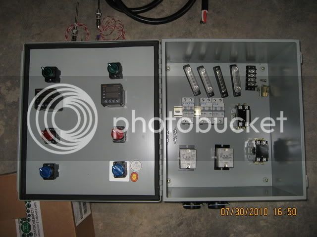
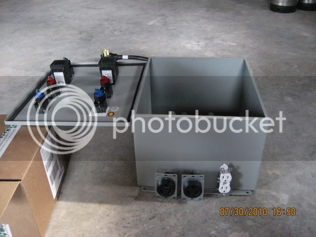
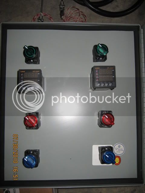
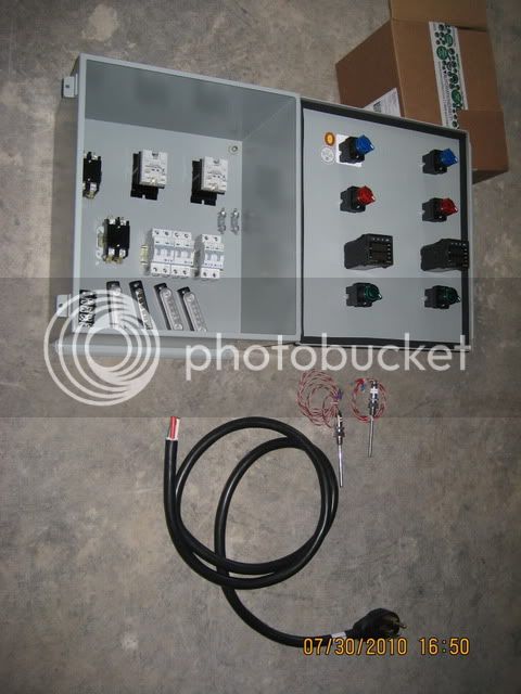
For the circuits
before the breakers the wire needs to be rated for 50 amps (the value of your mains breaker). You can use #8 THW/THWN or you can just use some of the wire (a foot or two) from your power cord.
The wiring after your breakers should be sized for the breaker value. #14 wire for the 15 amp breakers, # 10 for the 25 amp breakers.
I think you would only need 3 or 4 feet of each type and color. I suggest that you use stranded wire instead of solid copper as it is more flexible. Another thought for you. If you intend to use crimp on connectors, solder the crimped connection after crimping. This is important on the high current lines (heating element connections for example). Trust me on this one, it will save you a lot of grief down the road.
Hope this helps.

") .
.