Has anyone tried just duct taping the probe to the side of the fermenter? I wonder if the results would be more accurate than leaving the probe exposed in the freezer.
Worked for me.

Has anyone tried just duct taping the probe to the side of the fermenter? I wonder if the results would be more accurate than leaving the probe exposed in the freezer.
Has anyone tried just duct taping the probe to the side of the fermenter? I wonder if the results would be more accurate than leaving the probe exposed in the freezer.
Can anyone help modify this wiring diagram from post #991 to only use one outlet? Top plug for heat and bottom plug for cool.

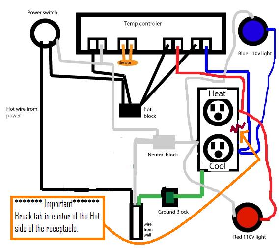
dtadpole said:Hopefully this will help. Chopped up the original image from post #991. -->Original post here!
Has anyone tried just duct taping the probe to the side of the fermenter? I wonder if the results would be more accurate than leaving the probe exposed in the freezer.
Hopefully this will help. Chopped up the original image from post #991.
Just make sure you break the metal tab that connects the hot side of the top and bottom outlet when using this wiring configuration.
Yes that would work too.couldn't the negative from the red light and blue light connect to the neutral block?
Yes that would work too.
I purchased one from another seller. (quality-link)It took about 2 weeks for it to arrive.

I see that terminal strips have varying amp ratings from 10-20 amps. What amp terminal block do I need to get?
I just used wire nuts. Terminal blocks are too much of a pain for only a few wires.
I see that terminal strips have varying amp ratings from 10-20 amps. What amp terminal block do I need to get?

")
I wonder if this thermowell will work:
http://www.northernbrewer.com/brewing/stopper-thermowell.html
Hey all. Wow, what a long thread... took a while to read.
I ordered a 110V controller from mixtea (?) on ebay 8 days ago. How many of you folks ordered from this seller and how long did it take you to receive your controller? I'm curious how long this will take to get to me from Hong Kong or wherever it's coming from. I'm concerned because I can't track my shipment. MixTea (?) didn't give me a tracking number.
I almost hate to beat a dead horse...however, you have to beat something from time to time!
I ordered this controller from Globalconn...same as most others in this thread. Awesome service and response.... Ordered last Monday BTW...however, today I received a model ETC-200+. It appears to be a similar controller, maybe a newer model??...instead of 4 buttons it has 2 rocker switches and on the back we have 12 connectors...actually 11 connectors although the spacing as well as the wiring diagram allows for twelve. There is actually no connector at position 10...between power in and the the sensor.
The wiring diagram is entirely different than what I have seen in this thread and expected based on the product description when I ordered. It shows the 11 connectors...110VAC in on pins 7-9, sensor on pins 11-12, 10a/220VAC compressor on 1-3, 10a/220VAC defrost on 5-6. I think I understand that the 220VAC rating on these is a limit and that 110VAC isn't an issue.
To my meager brain, this seems exactly the same but different. Compressor equals cool, Defrost equals heat, etc.
Here's a link to the only almost matching doc's I could find online... http://www.kibnt.com/uploadfile/microcomputertemperaturecontroller1/20091020020020kFmyF.pdf except both my doc's and my controller are labeled 110VAC at the input (7-9).
I'm not an electronics wiz or even an electrician, but I think this is a reasonably clear translation, but I would most welcome a wiser second opinion.
Assistance muchly appreciated.
Image: http://picplz.com/QZ1z

@android I think I'll use the below chart...

@Mobius570
1. Link to the seller...
2. I plan on it, don't know about the OP.
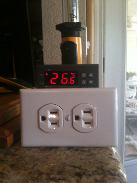
I built out my controller this weekend, and used this site as my primary guide (I realize the hot/cold on the controller are reversed - I adjusted for that).
I'm having an issue where my cooling outlet/bulb are active 100% of the time, even with the controller powered off. The heating outlet/bulb work as expected. I've confirmed that the two outlets are wired the same, and the hot wire from the power cord connects only to pins 1, 5, and 7 on the controller - there should be no direct (non-switched) power to the cooling side.
What would cause the cooling side to always be active?
How many degrees differential are you guys setteing these to?

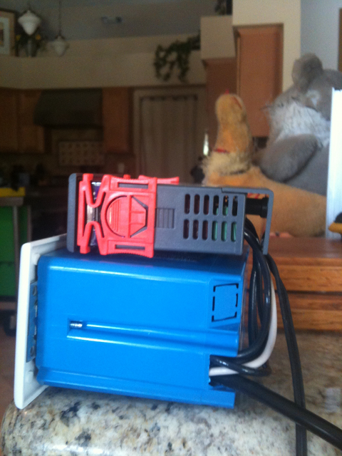
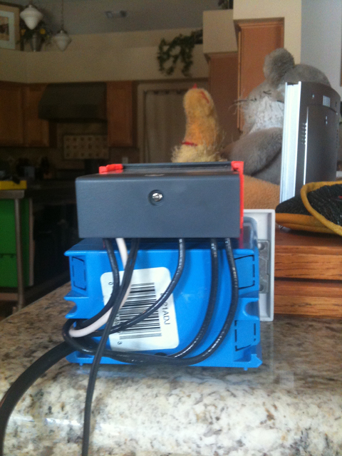
I had some spare electrical boxes and parts laying around, so I went the quick-and-dirty route:
Velcroed the controller on top of the box, works like a charm
Apparently made this just in time, as one of my brand new Johnson Controls A419 controllers just died
Yeah, but like I said, I used what I had laying around.You know that the controller itself will fit in one of the gangs, right?
I would have used a 2-gang but I had a 3-gang at hand.
M_C

I'm trying to find these on Lowes.com and can't. Does anyone know what they are specifically called? Damn thing is driving me crazy!!!
Enter your email address to join:

