shushikiary
Well-Known Member
Glad I could help, now send me free beer! ") lol j/k.
lol j/k.
lol j/k. lol j/k.
...As I am in no way shaw or form in any way capable of wiring anything...
Quote:
Originally Posted by AnthonyB
The seller said they will be getting more of these in the 110V variety in about 1 month time.
Middle of May, my email stated.
what's everyone using for the Difference setting. I think it's the #2 setting..
what's everyone using for the Difference setting. I think it's the #2 setting..
i guess i was wondering is 1 degree celius in air temp inside a fridge really going to even affect the fermentation taking place? but if you guys say so, i'll do..

Yup.Nice work! Any chance we can get a completed wiring diagram and photo of the guts now that you have the fan wiring all figured out. Very nice indeed!

Group buy?
http://www.diytrade.com/china/4/products/6281404/temperature_controllers_STC-1000.html
$13 each (200 minimum) plus shipping.
14 gauge would me more than sufficient. That can handle 15A.
Can anyone else chime in about my first question?
Since this plan requires that I take the temperature of the water around the carboy I wanted to see if there was a consensus about how to deal with that. Can I just drop the existing (rubbery looking) probe right in the water? Or do I need to put it in a thermowell of some sort?
Yup.
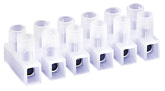
1.) I can't for the life of me find any terminal blocks to jumper the 120v over to the three sources needed for this build. Do I have to use a terminal block or would a wire nut work to jumper the 120v to three sources?
Yup.
is it just me, or are the instructions that come with these controllers vague and incorrect? i tried following the instructions to set the temp and it didn't seem to respond as it was supposed to. only when i started randomly punching the buttons did i finally get it set. i hope i can remember what i did next time!
has anyone written a better set of instructions?
This is the relay in question from Radioshack.I got my two controllers this week, very quick shipment!
I don't understand how this relay is working. I think it is activated by power to either of the two relay connections #1 or #3. This energizes the relay and powers the fan. I take it that this relay will be energized by either input without back feeding to the other, right? What is the part number or radio shack number of this relay so I can find a pinout and specs?
Enter your email address to join:

