ebay aquarium temp controller build

Homebrew Talk - Beer, Wine, Mead, & Cider Brewing Discussion Forum

Help Support Homebrew Talk - Beer, Wine, Mead, & Cider Brewing Discussion Forum:

This site may earn a commission from merchant affiliate links, including eBay, Amazon, and others.
I went to ebay and bought the controller before I read the rest of the thread and realized there was a also 220 volt one. I attempted to contact the vendor and cancel the order, but was informed it shipped today.
What would be required to use the 220 volt controller? The fermenter will be in the basement close to my electrical panel, so I could run a dedicated outlet/circuit.
I have done plenty of wiring in my home theater/bar room, but that was all just basic outlet/lighting wiring. I have also moved a clothes dryer (220v 30 amp) outlet over.
My background is food science and not electrical so I can't think of a way to make this work.

If you have 220Vavailble, it doesn't take much power to run the electronics. A lamp cord will be enough. For safety purposes just run the 220v independent of the rest of the control. It is only switches on the other side at that point. Do your 110V feeds totally separate.
 
If you bought this one:

http://cgi.ebay.com/ws/eBayISAPI.dll?ViewItem&rt=nc&nma=true&item=270696832865&si=6XcGCcX2Wa8OnPlKfASL6mh4dno%253D&viewitem=&sspagename=STRK%3AMEWNX%3AIT

Then I'm afraid that you are SOL. 220V in the home is just two 110V legs forming a split-phase system instead of a single 220V single phase system which the Europeans use. I looked at a few step-up converters and it'll be a lot cheaper to buy another temperature controller than to go that route.

I'd try it out if I were in your shoes. What's the worst that could happen, it won't work?

Hmmm.... I might be wrong here, but I don't think it matters whether you are in the US or Europe. If you connect 220v to that thing, it should work.

Whether that 220v comes from a 220v potential hot and a neutral (europe) or two 110v hots at opposite potential (US) should be irrelevant. The electronics won't have any idea there is a difference. They just see a difference of 220v between one incoming power line and the other.
 
I thought about that too, Walker, and that works well for analog devices (heating elements, etc); I'm just not sure how the digital unit will work. I'm a mechanical engineer so my knowledge of electrical theory is rather limited. That's why I'd try it out and see what happens.

He would still need the 220VAC receptical to be in the vicinity of the controller and will need to bring the power in safely to run whatever he intends to control. He could bring the split-phase power to the controller (I'd suggest a three conductor with ground, two hot, one neutral, and the ground), the two hot legs would be used to power the controller, and then one or both (one to heat and one to cool) of the hot legs can be used to power the controlled device. There's more risk involved due to the higher potential and larger breaker, so incorporating a GFCI breaker or outlet would be in his best interest.

Edit to add later: US residential 240 VAC supply is two 120 VAC in phase. Can you get a 240V potential if they are in phase?
 
\Edit to add later: US residential 240 VAC supply is two 120 VAC in phase. Can you get a 240V potential if they are in phase?

Our electrical service is done by center tapping the neutral off a transformer and then tapping the hots off opposite ends of the transformer. You end up with two 120v potential hot lines that appear to be 180* out of phase and the neutral at ground potential.

You will see 240v between the two hots.
 
If you bought this one:

http://cgi.ebay.com/ws/eBayISAPI.dll?ViewItem&rt=nc&nma=true&item=270696832865&si=6XcGCcX2Wa8OnPlKfASL6mh4dno%253D&viewitem=&sspagename=STRK%3AMEWNX%3AIT

Then I'm afraid that you are SOL. 220V in the home is just two 110V legs forming a split-phase system instead of a single 220V single phase system which the Europeans use. I looked at a few step-up converters and it'll be a lot cheaper to buy another temperature controller than to go that route.

I'd try it out if I were in your shoes. What's the worst that could happen, it won't work?

Nope. It is single phase with a center tapped transformer. I took a class with the guy that wrote the book. In fact he was in the process of writing it when I took the class and got a few chapters to preview. :D
http://www.amazon.com/dp/013975475X/?tag=skimlinks_replacement-20
 
Last edited by a moderator:
The jack I'm attempting to harvest is attached to a small circuit board. Did you use the whole thing or just the jack?

Is it possible to purchase the computer power supply type plug, like from Radio Shack, rather than harvest it from an old power supply. I like the idea of being able to unplug the power source from the control unit.

200x200-atx2power350.jpg

This style plug, just without the power supply.
 
dgoldb1 said:
Is it possible to purchase the computer power supply type plug, like from Radio Shack, rather than harvest it from an old power supply. I like the idea of being able to unplug the power source from the control unit.

This style plug, just without the power supply.

there are some builds in this thread like that. i was going to try to track one of those down myself. i doubt hw stores or even radio shack will have those in stock locally
 
220V in the home is just two 110V legs forming a split-phase system instead of a single 220V single phase system which the Europeans use.
Nope. It is single phase with a center tapped transformer.

US electrical codes confusing enough without adding to it with "technical" vs. "technically correct" terms for US 220V(240V?).
Hopefully no one adds to the confusion by mentioning that the "+" peak in the AC waveform, or the "+" wire in DC, is really "-". Did I just do that? It is just a naming convention, and has little bearing on the question at hand. Here is a brief explanation of the terms-

"Split phase" is shorthand/jargon for a US 220V "center tapped, 3 wire, single phase" style of service. A bit like "split phase", "center tapped, 3 wire, single phase"; potAto, (insert very long winded latin name for the potAHto species). If you are a Dan Quayle fan- potAtoE, potAHtoE. So being nit-picky and calling US 220V "single phase" means including "3 wire, center tapped" every time as well. Or, just using "split phase" like most people.

To address the current issue of plugging a EU 220V appliance into 220V service-
(since 110V service is also referred to as 120v, just like Euro "220v" is also referred to as 230v, I will use 110/120v, 220/240v (US), 220/230v (Euro)

The US 220/240V circuit uses a "center tapped" transformer resulting in (up to) a 3 wire circuit- 2 110/120V wires, with respect to the 3rd neutral wire; and with the 2 110/120V wires linked 180 deg out of phase with respect to each other. The neutral wire, combined with either of the 110/120v wires, is (mainly/only?) used to when 110/120V circuits (clocks, lights, controls) are needed within an appliance that is connected to a 3 wire 220/240V plug.

As an analogy, a house, in the US at least, is like a big appliance connected to a 3 wire 220/240V plug. Within the house, 110/120V circuits are made by connecting either of the hot 110/120v legs to the neutral. The ground wire for outlets within the house is attached to a conductor (copper rod usually) connected to earth (dirt near the house).

That being said, some Euro 220/230V appliances will work if wired to the two hot legs of US 220/240V service. Unless it is a simple resistive heating device, the appliance needs to be checked to make sure that the plug/power doesn't need to be oriented a specific way in its native socket, i.e. it requires the neutral and hot on specific pins of the plug/socket. Specific hot/neutral pins usually means there are groundings in the internal circuitry. These circuits may not function properly if hooked up to the two hot legs of US 220/240V service since both legs are "hot", and, depending on the circuit, could power exposed surfaces or cause internal shorts. Either is bad juju.

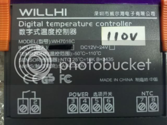
This controller does not specify a hot and neutral pins for the input power, and may work, when connected to the hot legs of a US 220/240V circuit. Even if it does function completely, it may not be worth doing for several reasons. For permanent use, a new 220/240V outlet with a smaller 15 amp main breaker should be installed for safety reasons. Also, how a GFCI would react to this bastardized setup is unknown, to me at least, and needs to be investigated.

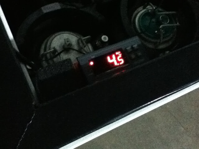
As suggested by several previously, it seems like the best use of these misordered 220V controllers is as a temperature display. The outlet box isn't needed, so it ends up being a ~$30 temp display. That isn't much more than a nice digital temp display would cost anyway. I would be more irritated by having to wait another month (and counting for me, anyway) for the reordered 110/120V version to arrive.
Cliff
 
Is it possible to purchase the computer power supply type plug, like from Radio Shack, rather than harvest it from an old power supply. I like the idea of being able to unplug the power source from the control unit.

200x200-atx2power350.jpg

This style plug, just without the power supply.

Unplugging it from the wall outlet depowers the control unit, doesn't it? If the outlet is far away or difficult to get to, you could just make the cord very short and use an extension cord. That is what you would end up with anyway. The computer style "female around a male" may look sexier, but it is no fun having to track down a computer style power cord when the original gets misplaced.
 

I recommended running ONLY the controller portion off of the available 220V and wiring the rest from a 110V source so as not to get too deeply into this kind of stuff. It depends on how comfortable the poster is with doing the wiring.
 
I recommended running ONLY the controller portion off of the available 220V and wiring the rest from a 110V source so as not to get too deeply into this kind of stuff. It depends on how comfortable the poster is with doing the wiring.

IMO, running separate power feeds to the project box makes this a lot more cumbersome and unattractive. It's not hard to tap the outlet off one hot and the neutral from the 240V feed.

Then again, we are nearly 800 posts deep in this thread and there are still people who are having trouble with the 120v wiring, so.... :)

Well, that is what I would do. I'd use one hot for each different plug. I have such a feed in the basement. I'm just not that comfortable trying to give a step by step on what I would do. I'd rather someone understand how the thing works and then reason out a solution.

Box is simple.

1&2 power the electronics
3&4 connects the probe
5&6 a switch (no power)
7&8 a switch (no power)

To use the switch, break one side of your line to whatever you want to control (should be the hot side) and run the two ends to 5&6 or 7&8.

What does the original design do for you? It makes use of the fact you already have run power to up to the box.
 
I recommended running ONLY the controller portion off of the available 220V and wiring the rest from a 110V source so as not to get too deeply into this kind of stuff. It depends on how comfortable the poster is with doing the wiring.

What I posted is directly related to powering only the controller portion with US 220/240V. The 240V supplied by US 220/240V split phase, center tapped, single phase, ...... is not the same "in every way" as EU 220/230V. 2 120V "out of phase" hots do not equal 1 240V hot and 1 neutral. If we both have to grab 1 of the 4 wires listed, can I go first? This is true especially when the circuit powered by the service uses the "neutral=ground" style of circuit design. I think this style of circuit is rare these days, but some manufactures try to save that $.03 any/every way they can.

Before even attempting to test the unit on US 220/240V, the controller should be rewired. Just powering the controller's power inputs is enough/best. The relays should click loud enough to hear, or could be tested with a multi-meter (which is a must have tool for attempting this anyway). The standard schematic (in this thread) is not correct for wiring to US 220/240V service. There is an extra hot in the mix.

If the controller functions properly on US 220/240V service, and even if only the controller portion were wired up to US 220/240V service, a dedicated breaker/circuit with a smaller (than US 220/240V standard of 20-30 amps) breaker should be used. The concern regarding circuit breakers is not about how much power the controller uses, but the power available to it with a 20-30 amp 240V breaker. If something goes wrong, that is what will be available- 3-4 times normal household outlet power.

While running a separate 110/120V circuit to feed the relays is not needed, a GFCI installed in the hot leg of the relay circuits would be a good idea, since a panel GFCI for the 220/240V may not function or provide protection since part of the circuit only uses a single 110/120V leg. That is a question for an electrician, or maybe not even worth asking- probably safer to just install a GFCI for the 110/120V service inside the project box.


Cliff
 
i heard if you put a sticker that says 110V over the bit that reads 220V it helps...

like this guy did...

IMG_20101216_090204.jpg


:D :ban::p
 
that photo looks familiar LOL.... I have no idea what has been changed all I know is its working right out of the box connected to a 110 outlet.

-=Jason=-
 
is it a possiblity that the manufacturer is doing something simple to convert a 220 to a 110 and putting a sticker over it? I thought the coils insided were 220 switches or something...
 
Then again, we are nearly 800 posts deep in this thread and there are still people who are having trouble with the 120v wiring, so.... :)

People are also still ordering the wrong controllers as well- 220V units, or the single stage (heat or cold, but not both). The ebay links break after ~30 days, or less. This may be a case for a sticky/wiki about these controllers.

Regarding the schematic causing issues- If an unsimplified version were available to understand the basic circuit, the simplified wiring version might make more sense to people unfamiliar with reading schematics.
 
The GFI in the panel will still work fine.

That makes sense. It must monitor for the sum of the currents on all 3 legs to be ~0. So, any fault to ground on either live leg will cause it to trip. Just make sure to wet down the floor, and wear your foil slippers. It would still be wise to put a suitably sized breaker on the circuit in case you forget your foil slippers. The GFI doesn't know the difference between your hair catching on fire or a normal electrical load, if you don't short the current to ground somehow.
 
Here's mine. I don't know if you can buy the female part, I got mine out of an ancient computer from like '92 I grabbed from my parents. This same computer I got Rare earth magnets for my stir-plate build.

143f0ao.jpg


This build was real simple. I've never really wired anything, and was pretty intimidated at first. I just read trough all the post's, and looked at Walker's advice, and studied the original wiring schematic until I had it figured out! Thanks for all the input everybody!
 
I decided to just mount the controller inside the newly built keezer. I mounted the controlled outlet on the back of the collar with a couple of convenience outlets. The controller sits inside the front corner, as it is more "set it and forget it."

Sorry for the lack of quality, basement at night with an iPod :cross:

IMG_0065.JPG


IMG_0063.JPG
 
I would be concerned with moisture and your lack of enclosure with that controller.

-=jason=-
 
I've had one of mine mounted in the collar of my smaller keezer since April of last year with no issues. Just a bead of silicone around the inside and outside to keep it airtight. No ill affects from the moisture so far, I figure at that price if something goes haywire I'll just pick up a new one!
 
I'd rather error on the safe side and have it enclosed in a box of some sort with silicone sealing it. But hey thats just me. should my controller go down and i had to wait 3 weeks for a new one that would suck. now maybe you have a backup on the shelf just in case this one bites the dust.

-=Jason=-
 
The specs state it is operable in 20-85% RH, no condensation. My keezer is dry, and humidity is controlled via silica gel. There is no frost or moisture visible.

The connections are wrapped and protected from liquid as poppets can/will spray where you don't want them too.
 
Hey guys-

I've got a small kegerator that had an inaccurate dial thermostat. I replaced it with the aquarium temp controller. The old thermostat had the two sensor wires, live, neutral, and ground. So when I replaced it I pigtailed the live wires so that they fed spot 1 and 8 on the temp controller. I did the same with neutral for spots 2 and 7. When I plug in the kegerator the temp controller comes online and everything looks good. It is in compressor delay mode though. As soon as it tried to kick the compressor on I hear a split second of the compressor working, and then the controller resets and goes back into compressor delay mode again. I was able to get it working using a seperate power cable to feed spots 1 and 2, but I'd rather be able to use a single cable. Is it possible there is noise/interference coming back from the compressor when it kicks in that is resetting the controller?

Thanks.
 
Hey guys-

So when I replaced it I pigtailed the live wires so that they fed spot 1 and 8 on the temp controller. I did the same with neutral for spots 2 and 7.

Thanks.
This sounds scary. You should unplug it immediately, and read the schematic until you thoroughly understand it. Especially if you are not going to wire it the standard way as described in this thread.
The neutral does not get attached to the solenoid/switched posts. On the controller, the neutral should only go to one of the input power posts (#1 or #2). This is assuming you are talking about the pinouts for dual stage with 7 & 8 being the cooling side solenoid switched posts.
 
I replaced it I pigtailed the live wires so that they fed spot 1 and 8 on the temp controller. I did the same with neutral for spots 2 and 7.

This is wrong. If you really did this, you have a situation where neutral and live wires will be connected together (pins 7 and 8) as soon as the controller tries to kick on the cooling device.
 
This is wrong. If you really did this, you have a situation where neutral and live wires will be connected together (pins 7 and 8) as soon as the controller tries to kick on the cooling device.

I may not have explained myself correctly. I didn't actually connect the live and neutral together, but you made me solve my problem anyway.
 
I may not have explained myself correctly. I didn't actually connect the live and neutral together, but you made me solve my problem anyway.

If you connect a live and neutral to pins 7 an 8 (cooling solenoid), while you may not have hardwired the live and neutral together, the controller will finish the job for you and connect them when the solenoid closed the switch.

Are you sure you understand the schematic and what the controller does?
 
One of the wires was not a neutral. I am afraid I mispoke due to my lack of knowledge. However, everything is working correctly now. I am running from a single power cord so that everything looks stock except for the controller mounted on the rear of the kegerator. It has been tested. Thanks for the help.
 
I am running from a single power cord so that everything looks stock except for the controller mounted on the rear of the kegerator. It has been tested.

If keeping the kegerator looking stock was your goal, you could have left the original thermostat in place, turned it to its lowest setting, ran the new thermo sensor/wires inside, and plugged it into a controller box built according to a vetted schematic. It would not only have looked stock, it would have been stock. You would have missed out on all that fun "testing" with live wires, though.

By the way, you may have removed the defrost circuit in disconnecting the original thermostat. Your kegerator may or may not have had one, and it may or may not be critical, depending on your kegerator. More "testing" I suppose.

Thanks for your condescending remarks. I did not want an external controller box. I wanted a single cord coming from the kegerator that would plug directly into the wall. If I have a problem with defrosting, I will reinstall the original thermostat and use the temp controller relay to cut its circuit. Try not to be so "testy."
 
That makes sense. It must monitor for the sum of the currents on all 3 legs to be ~0. So, any fault to ground on either live leg will cause it to trip.

Yup.

Just make sure to wet down the floor, and wear your foil slippers. It would still be wise to put a suitably sized breaker on the circuit in case you forget your foil slippers. The GFI doesn't know the difference between your hair catching on fire or a normal electrical load, if you don't short the current to ground somehow.

I am trying to understand if this was some humor or an insult or what....
 
Thanks for your condescending remarks. Try not to be so "testy."

Who's being testy? You don't expect to get some eye rolling type remarks after posting a question about debugging an obviously miswired circuit; then replying, a bit cryptically, that one of the 3 wires available (live, neutral, ground) wasn't neutral (?); and that "everything is working correctly now" and "tested".

Perhaps, for users attempting your conversion and general knowledge, you could post what you encountered/discovered so someone else won't make the same mistake.
 
Yup.

Quote:
Originally Posted by cwi
Just make sure to wet down the floor, and wear your foil slippers. It would still be wise to put a suitably sized breaker on the circuit in case you forget your foil slippers. The GFI doesn't know the difference between your hair catching on fire or a normal electrical load, if you don't short the current to ground somehow.

I am trying to understand if this was some humor or an insult or what....

The "you" was the royal/generic you. Just a comment so people understand that a GFI isn't a cure all, and that using an existing dryer/stove 220V circuit with a 30 amp breaker for one of the 220V versions of this controller is not a good idea, even if it is a GFI/breaker combo. The GFI will only trip if the current goes to ground. If the two hot legs make a circuit, through a person or otherwise, with no ground path, the breaker limit is the only thing that will stop the flow.
 
The "you" was the royal/generic you. Just a comment so people understand that a GFI isn't a cure all, and that using an existing dryer/stove 220V circuit with a 30 amp breaker for one of the 220V versions of this controller is not a good idea, even if it is a GFI/breaker combo. The GFI will only trip if the current goes to ground. If the two hot legs make a circuit, through a person or otherwise, with no ground path, the breaker limit is the only thing that will stop the flow.

Ok, sure.

But if you put yourself in a situation where you have created a short circuit through your own body, then it really doesn't matter if you were messing with 120v or 240v. You're in deep poo poo either way.
 
Back
Top