Brutus Build # pick one

Homebrew Talk - Beer, Wine, Mead, & Cider Brewing Discussion Forum

Help Support Homebrew Talk - Beer, Wine, Mead, & Cider Brewing Discussion Forum:

This site may earn a commission from merchant affiliate links, including eBay, Amazon, and others.

bbarr21

Well-Known Member
Joined
Sep 22, 2010
Messages
99
Reaction score
8
Location
Fuquay-Varina
I have recently spent hours reading and comparing the various Bruti all around the interwebs. And I decided that I was ready to auto mat my single tier system for the easy of consistency and replication of recipes. So I figured I would document my build as everyone else has so thankfully done.

But to start Big thanks to Lonnie Mac for his inspiration to all of there amazing builds. And from his lead a big thanks to everyone who has builds post here on HBT. They have been helpful and inspirational.

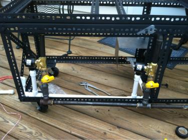
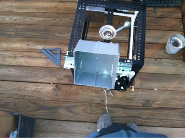
So as a starting point, I had a Weldless Walace like single tier. 3 keggles, one march pump 809, weldless fittings from Bargainfittings.com. Started with a homemade CFC switched to the Chillius Convoluted CFC. 3 Bayou Classic High Pressure burners (turkey fryer burners)

I wanted to automate my heat for the HLT and MLT add pilot lights for all 3 burners, and add a second march pump for recirculation and fly sparging.

I decided to use love controllers for the control and electric solenoid valves for the gas control. I wanted to integrate a timer into the control panel so I choose to spend the extra money on the love timer, aesthetic reasons mainly. And I am changing to the 10 jet burners with a pilot light.

If anyone has any inspiration or cation as I go please chime in for me and everyone.
 
This is the initial build

image-2554271711.jpg

image-1944549443.jpg

image-521229441.jpg

image-1414828473.jpg

image-3703946094.jpg

image-2759376118.jpg

image-2527543651.jpg

image-2949917829.jpg
 
These were som simple mods I made for the cfc adding an inline thermometer and aeration stone from the output of the chillius.

image-949919271.jpg

image-4228475278.jpg

image-2677629925.jpg
 
Then the beginning of my Brutus adaptation.

I used a 8x8x4 PVC enclosure
image-177035204.jpg

The beginning of the wiring, one love controller ts2-010, 2 8 port bus with 8 way jumpers (the jumpers just save the tedious wiring of each port to the next, just a slotted piece of metal) a ground bus, main power switch and 2 on-off-on switches to power the solenoids
image-2866690260.jpg

My second love controller ts2-010, the low cost digital timer ($45) from Dwyer-instruments two 5' TS-6 temperature probes and 2 TS-W thermowells
image-523722482.jpg

Getting it all wired up
image-1796178940.jpg

Wired the solenoids and the march pump(soon to be pumps (2)) through the PVC to protect the wiring and give it a cleaner look
image-2250984987.jpg
 

Attachments

  • image-1911191171.jpg
    image-1911191171.jpg
    11.8 KB · Views: 2,292
  • image-670609899.jpg
    image-670609899.jpg
    25.4 KB · Views: 2,342
Explaining my control panel... From top to bottom then left to right.

image-2300660529.jpg

The top display is the love timer. Able to set from 0-999 secs/min a 2 beep alarm sounds at the end of the time. It can be manually over ridden, if the case was that is was wired as a switch, not so in my case, for now atleast.

The middle display is the love ts2-010 that is wired to control the HLT. There is tons of info on love controllers on this forum so I wont go into it unless someone asks.

The bottom display is the same set up as the middle, only it controls the MLT.

The switches directly to the right of the two ts2's are HOA switches, they are DPDT switches wired to give full control over the solenoid and in turn burner. When the switch is thrown up it will be in "auto" mode and allow the love controller to manage the burner.
When the switch is in the middle it is in off position and the burner will no be fed any gas.
When the switch is thrown down it is in the "manual" position and bypasses the love controller and the burner will be lit.

The switch to the top right is the main power switch to the system, simple on-off toggle switch, I want to put a key switch here and label off as "drink" and on as "brew" but thats again not function just aesthetic.

Below that switch were the tape is will be 2 lighted rocker switches corresponding to the 2 march pumps.
The switches will be wired so that the led is lit when the pumps are on.
 
These Brutus style tee's are very unclear to me...

image-4282929142.jpg

First problem love TS-6 probe doesn't fit their TS-W thermowell ... Is this what Lonnie Mac was saying about filing off the coating? I think that boring out the well would be easier..

I was also thinking about attaching the tee with a closed nipple instead of a QD.. Any thoughts on that?
 
1/2" electric solenoid 110vac viton seal from valves4projects it's rated 0-50 psi found it cheap on eBay
 
bbarr21 said:
1/2" electric solenoid 110vac viton seal from valves4projects it's rated 0-50 psi found it cheap on eBay

Thanks I will definitly be using them. Where did you score that enclosure? I'm in the process of piecing everything together for my build and what I have pictured is very similar to yours
 
Did some work got the pump switches on the panel and everything wired from the hot bus and put holes in the side for the the probes

image-2299562798.jpg

finally figured out what to do about the probe and thermowell problem... Make the wells bigger! The brass on the wells was fairly thick so I decided to bore it out very slowly using 4 different drill bits.

image-1786054051.jpg

Starting with the step bit to make sure the first bit was very straight
Then a .266" bit
Then a .272" bit
Then a .278" bit

Finally with several steps I got the probe to fit snugly in the well.

image-1849382055.jpg

here are my 2 tee's one with a QD hose attached. Thinking about attaching the tee directly to the ball valve on the one keggles via a closed SS nipple
 
Huge difference... DIY CFC was a 25' run the chillius is ~8' but the inner tube is convoluted which adds a lot more surface area for heat exchange. And it adds to the turbulence of the wort forcing a large portion of the wort to interact with the heat exchange enabling a quick temperature drop. 6 gal batch chills to ~65 in 5-6 minutes with 60 degree ground water.
 
Got my second March Pump 809 and bracket in the mail yesterday so hoping to finish up the build today... More pics to come
 
Did a bunch of work on the gas and electrical side of the system today.

image-2415687309.jpg

After everything was dry fit it was time to re wire and replumb everything with sealant.

image-2934453168.jpg

My two march pumps


image-182571045.jpg

In the middle of wiring/plumbing, kind of tedious having to fit the two systems inside and outside of the frame...

image-1507981999.jpg

1 of 2 of the automated heat source set ups with pilot, waiting for the flex tubing for the burners to arrive in the mail

image-455076654.jpg

The swing arm mount for the control panel, made with the same slotted angle iron as the rest of the frame.

image-3212006505.jpg

The swing arm in stored position. There is a slotted iron piece with a screw for the end of the swing arm to lock in storage position.

image-273750150.jpg

View from behind, you can see storage lock on right.

image-2735166798.jpg

The Brutus setup on brewing position. 95% wired hoping to finish tomorrow.
 

Attachments

  • image-1505225156.jpg
    image-1505225156.jpg
    19.5 KB · Views: 681
Originally just to the pilot but the other set for the burners is in the male. Can't beat their pricing and they ship super fast!
 
bbarr21 said:
Originally just to the pilot but the other set for the burners is in the male. Can't beat their pricing and they ship super fast!

Sweet. Do you just connect it straight to the oriface? Also does anyone know the thread size for the BG 12 oriface so I can order these awhile ?
 
I am designing the wiring for my asco valve, control panel and BCS460. I found that the asco can pull 40 Ac amp when on. Now the nema plugs I am planning to use are rated at 30 A. Mi assumption is that if I pull 40 amps. Either manuals or thru my solid state relay this 40 amps are coming in the the power cord. But the connector show handling 30A. I think The plug is underrated. So I am not sure what to-do.

I am trying to fit every thing in a box that is screw to the Brutus bench. Plans are to have a GFI receptacle underneath for the 2 march pump. Then a lug for the AC in. the a receptacle for the PC connection. And a power switch. Laptop will sti on top of box.

I was even thinking on using a receptacle with an integrated fuse and switch. But Amp rating is too low.
 
A valve that takes 40A!!!! i think you got something wrong here i cant imagine a valve taking nearly that much. are you sure it is not 40mA???? post the specs or exact model you are using... ether you are mistaken on the 40A or you are using some crazy valve
 
Just letting you know some info that I had to figure out on my own. I just finished 2 brutus RIM systems for a buddy and myself. I ended up using the 10" propane jet burners that I purchased from Instawares on line for 35.00 and when I hooked them up to natural gas they actually burn and nicer blue flame for pennies compared to burning propane. I have been brewing ten gallons every weekend for the last couple of months and haven't even noticed an increase in my heating bill. We did have to build circular surrounds around the burners for them to light correctly though. I also found an out let for the pilot because I didn't pay the extra money for the burners with the pilot installed. The pilot for each burner cost me 9.50 each.
 
The link you provided stated the valve takes 6.1W. So that would be 120*A=6.1. Witch would equal .050A or 50mA
 
one on the sheet is 40VA holding current. It is key to note VA is not the same as A. this stands for "Volt Amps" and and for DC is the same as watts so if fairly pointless for DC but is commonly use to reference "power" in the AC world because it takes into account the "power factor" i don't think power factor would be an issue for you so assuming a power factor of 1 that would mean 40W holding. 120*A=40 = .333A or 333mA. you can google VA to watt conversions if you need more info
 
thanks Ialso did some research yesterday and came to the same conclusion. Now I am trying to find a receptacle that I can plug my 2 pumps and switch them on alternate. Vs bringing the wires in to the enclosure. The goal is to be able to take the full enclosure out of the brutus . basiccaly plug and play
 
Brew today for the first time on my brutus! everything worked great.
My one concern was i wasn't getting much velocity out of my whirlpool valve which hardly created a trub cone. I pulled a lot of the broken down hops into my primary which im not terribly worried about in this beer but would love to fix this problem in the future.
 
looking good... it took me a very long time to decide on what i wanted to do, i also did a Brutus 10 but I welded my stand last summer and just finished adding my last few items a week or so ago.
Good luck and keep up the great work.
 
Hey Brian,
I realize this is a fairly old post but I was wondering if you could help me by sharing how you wired your Love Controller to the 3 position (on-off-on) switch. I am building a Brutus clone and am stuck on this wiring problem. I think I got it figured out but would love a second opinion.
Thanks,
John

Explaining my control panel... From top to bottom then left to right.

View attachment 42988

The top display is the love timer. Able to set from 0-999 secs/min a 2 beep alarm sounds at the end of the time. It can be manually over ridden, if the case was that is was wired as a switch, not so in my case, for now atleast.

The middle display is the love ts2-010 that is wired to control the HLT. There is tons of info on love controllers on this forum so I wont go into it unless someone asks.

The bottom display is the same set up as the middle, only it controls the MLT.

The switches directly to the right of the two ts2's are HOA switches, they are DPDT switches wired to give full control over the solenoid and in turn burner. When the switch is thrown up it will be in "auto" mode and allow the love controller to manage the burner.
When the switch is in the middle it is in off position and the burner will no be fed any gas.
When the switch is thrown down it is in the "manual" position and bypasses the love controller and the burner will be lit.

The switch to the top right is the main power switch to the system, simple on-off toggle switch, I want to put a key switch here and label off as "drink" and on as "brew" but thats again not function just aesthetic.

Below that switch were the tape is will be 2 lighted rocker switches corresponding to the 2 march pumps.
The switches will be wired so that the led is lit when the pumps are on.
 
Back
Top