BruControl: Brewery control & automation software

Homebrew Talk - Beer, Wine, Mead, & Cider Brewing Discussion Forum

Help Support Homebrew Talk - Beer, Wine, Mead, & Cider Brewing Discussion Forum:

This site may earn a commission from merchant affiliate links, including eBay, Amazon, and others.
Im not really sure what we are looking at here. I think you have a breaker, ac contactor, DC relay, physical switch, and a plug. What are these doing? Where is the DC power coming from and how is it wired to your board? Is the plug for an AC unit or a fridge? And is the power supply for the RTD from the same power circuit? If your 5v power supply is on the same circuit then it will be affected by the inductive load. You could also try a capacitor across the + and - on the 5v to smooth it out.
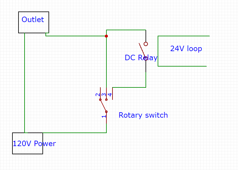
You are correct, the picture shows a breaker, ac contactor, DC relay, physical switch, and a receptacle, lets call this the subpanel. The idea behind this is I plug this subpanel into my main panel. The 24v DC output from the main panel controls the DC relay which controls the contactor. This lets power to the fridge (which is an air conditioner). I believe the answer to your power supply question is Yes, the 5v amplifier board and 24vdc output are on the same circuit. To clarify, see attached wiring diagrams, the first shows the main panel the second shows the sub panel. Regarding the sub panel, only the dark gray lines are currently wired. When finished, this will control a 240v AC, not 120v (as shown).

I hoped to provide more information on the wiring diagram but my trial limited out the QTY of features, the website wouldnt allow my payment o_O. I appreciate the help.

I see the dip from SPI sensor when A/C cycles. This is also observed when the AC is manually controlled (via sub panel) and NOT connected to output of the main panel. For this test, both sub panel and main panel are on completely different circuits. Also, everything is working fine when I use a lightbulb or a heatlamp at output. Something to do with the A/C

Looking forward to hear any criticism to the below diagrams.


MAIN PANEL.png
AC SUBPANEL.png
MAIN PANEL.png
 
Last edited:
So, if I understand correctly, to control your A/C unit, you have DC 24V power directly from your power supply going to the "sub-panel". The 24V is turned on/off with the rotary switch manually. When rotary switch is "on" it closes a relay which allows your sub-panel to see 120V power. Then when 120V power is turned on, it powers a contactor that turns on the A/C. Is there a reason why you have the AC contactor? You are already controlling your A/C power via the DC relay, and you are adding an inductive load that triggers another inductive load.

Is the sub-panel AC powered by the same AC circuit that powers your 24V power supply (all on one breaker at your house breaker panel)? If so, you probably need the MOV and/or snubber as in the brucontrol schematics.
 
Last edited:
So, if I understand correctly, to control your A/C unit, you have DC 24V power directly from your power supply going to the "sub-panel". The 24V is turned on/off with the rotary switch manually.
24V DC runs through the relay board which is controlled by the Arduino Mega. Then it runs out of the main panel to the sub-panel. The rotary switch either manually activates the contactor or its in auto which utilizes the Arduino Mega control described above.

When rotary switch is "on" it closes a relay which allows your sub-panel to see 120V power. Then when 120V power is turned on, it powers a contactor that turns on the A/C. Is there a reason why you have the AC contactor? You are already controlling your A/C power via the DC relay, and you are adding an inductive load that triggers another inductive load.

The 24v DC coil relay allows for automatic control, the AC contactor allows for manual control. I didn't know any other way to achieve this. In the event that the auto circuit provides 24v and the manual 24v wouldn't this overload the coil on the relay?

Is the sub-panel AC powered by the same AC circuit that powers your 24V power supply (all on one breaker at your house breaker panel)? If so, you probably need the MOV and/or snubber as in the brucontrol schematics.
In testing I made an effort to ensure the sub-panel and main panel were on separate breakers in my house panel. How do I figure out which MOV and/or snubber to use?
 
24V DC runs through the relay board which is controlled by the Arduino Mega. Then it runs out of the main panel to the sub-panel. The rotary switch either manually activates the contactor or its in auto which utilizes the Arduino Mega control described above.


The 24v DC coil relay allows for automatic control, the AC contactor allows for manual control. I didn't know any other way to achieve this. In the event that the auto circuit provides 24v and the manual 24v wouldn't this overload the coil on the relay?


In testing I made an effort to ensure the sub-panel and main panel were on separate breakers in my house panel. How do I figure out which MOV and/or snubber to use?

You have the 12V supply to the sub-panel running through the 8ch relay board? If so, then you have a relay, driving a relay, driving a contactor, driving an A/C unit, is this correct?

For the rotary switch from the diagram, it looks like you have it just as a manual on/off for the 24V dc power from the mega relay, so if your mega turned it on, you could cut it manually with the switch. Is the breaker the switch next to it on the diagram?
 
You have the 12V supply to the sub-panel running through the 8ch relay board? If so, then you have a relay, driving a relay, driving a contactor, driving an A/C unit, is this correct?
Now I read this and see how silly this is.. I will eliminated the middle man.

For the rotary switch from the diagram, it looks like you have it just as a manual on/off for the 24V dc power from the mega relay, so if your mega turned it on, you could cut it manually with the switch. Is the breaker the switch next to it on the diagram?
I cant find a DPDT electrical symbol in the software I am using so I put to SPST switches nest to each other. Check out the revised diagram...maybe this would work better?

The switch/contactor on the left are for main power in. The stuff on the right is for the 120v AC control. The light gray in the center is future 240v AC control.

A_C SUBPANEL REV2.png
 
Now I read this and see how silly this is.. I will eliminated the middle man.


I cant find a DPDT electrical symbol in the software I am using so I put to SPST switches nest to each other. Check out the revised diagram...maybe this would work better?

The switch/contactor on the left are for main power in. The stuff on the right is for the 120v AC control. The light gray in the center is future 240v AC control.

View attachment 652620

I would lot run 120AC and the 24DC power in the same switch.

Is there a reason you are using a switch and a contactor on the left? Why not just the switch?

Also, what are you trying to achieve with the manual switch for the A/C? Do you want to be able to turn on or off the unit regardless of what the software is set to? Or do you just want to be able to turn off the unit regardless of what the software is set to?
 
In both of your "Sub Panel" diagrams if I'm interpreting them correctly is that your load (120VAC) is drawn thru the 3 POS switch to feed your 15A receptacle correct? What is the AMP rating on each side for that switch, as most general purpose ones I've seen are 10A ? The reason I ask is that you might want to consider some sort of inline fusing upstream of the switch and downstream from your contactors as you could potentially have a 15A load. Either that or consider switching only the coil of the contactor with the 3 POS.
For your EMI issue a suggestion to reduce some of your EMI noise would be to replace your 3 POS and contactors with 2 appropriately sized (AMPS) SSR's.. 1 AC for manual mode and 1 DC for Auto Run. Contactors by nature are noisy due to their mechanical opening when the coil releases, thus you need to suppress this with a snubber circuit across the coil. I placed snubbers across 4 of my contactors and my spike/disconnect issues disappeared.
If you still wanted true manual control via switch just use a simple 2 way switch to to turn on/off your control wire (VDC) to the SSR which is fed from your PS. The other SSR (Auto) would be controlled from the MEGA.
I would also suggest not bringing AC and DC functions into 1 switch.
 
Last edited:
I would lot run 120AC and the 24DC power in the same switch.
Understood, ill make the modifications.
Is there a reason you are using a switch and a contactor on the left? Why not just the switch?
The switch and contactor on the left are the main power contactor. I am using a switch to turn the panel on/off via Estop, the main contactor is rated as such to handle the potential 20A draw from the 240V receptacle and 15A draw from the 120V receptacle. The switches I have are not rated for the 35A calculated total.

Also, what are you trying to achieve with the manual switch for the A/C? Do you want to be able to turn on or off the unit regardless of what the software is set to? Or do you just want to be able to turn off the unit regardless of what the software is set to?
This is correct, I want to be able to turn on or off the unit regardless of what the software is set to.

In both of your "Sub Panel" diagrams if I'm interpreting them correctly is that your load (120VAC) is drawn thru the 3 POS switch to feed your 15A receptacle correct? What is the AMP rating on each side for that switch, as most general purpose ones I've seen are 10A ? The reason I ask is that you might want to consider some sort of inline fusing upstream of the switch and downstream from your contactors as you could potentially have a 15A load. Either that or consider switching only the coil of the contactor with the 3 POS.
Good point. I failed to realize I will be exceeding the amp rating of the switch.

For your EMI issue a suggestion to reduce some of your EMI noise would be to replace your 3 POS and contactors with 2 appropriately sized (AMPS) SSR's.. 1 AC for manual mode and 1 DC for Auto Run. Contactors by nature are noisy due to their mechanical opening when the coil releases, thus you need to suppress this with a snubber circuit across the coil. I placed snubbers across 4 of my contactors and my spike/disconnect issues disappeared.
If you still wanted true manual control via switch just use a simple 2 way switch to to turn on/off your control wire (VDC) to the SSR which is fed from your PS. The other SSR (Auto) would be controlled from the MEGA.
I would also suggest not bringing AC and DC functions into 1 switch.
I will revise my diagram and post when complete. I appreciate the help. I would like to eliminate unnecessary noise but I feel the AC is the issue not the contactors. I dont have any issues running my heat lamp and I see the spike/disconnect issue even with the AC turning on manually (without contactors etc).
 
Can a 'sleep' or 'wait' command be incorporated into an 'if' statement? Since I'm getting the spikes, this is causing my alarms to go off. Id like to incorporate a delay for the alarm to act allowing time for the spike to correct itself.

The first 'if' statement is to cause the delay, the second will sound the alarm (providing the condition is still met). Perhaps I need to use a timed based deadband?

I understand I could use a timer element and incorporate an alarm but this seems rather clunky. I don't want a bunch of elements and would rather rely/learn the script behind such tasks.

if "FV-1 TEMP" value > AlarmHigh
sleep 15000
endif

if "FV-1 TEMP" value > AlarmHigh
"FV-1 ALARM" Active = True
FV-1AlarmStatus = "HIGH TEMP"
endif
 
Last edited:
Can a 'sleep' or 'wait' command be incorporated into an 'if' statement? Since I'm getting the spikes, this is causing my alarms to go off. Id like to incorporate a delay for the alarm to act allowing time for the spike to correct itself.

The first 'if' statement is to cause the delay, the second will sound the alarm (providing the condition is still met). Perhaps I need to use a timed based deadband?

I understand I could use a timer element and incorporate an alarm but this seems rather clunky. I don't want a bunch of elements and would rather rely/learn the script behind such tasks.

if "FV-1 TEMP" value > AlarmHigh
sleep 15000
endif

if "FV-1 TEMP" value > AlarmHigh
"FV-1 ALARM" Active = True
FV-1AlarmStatus = "HIGH TEMP"
endif
What you are describing is similar to debouncing a switch. You can search and find lots of example code to get an idea of how to implement it, but essentially you will want to create a counter that increments while the condition is met. If the condition goes away the counter is reset. If the counter ever increases beyond a threshold then you trigger the alarm.
 
Understood, ill make the modifications.

The switch and contactor on the left are the main power contactor. I am using a switch to turn the panel on/off via Estop, the main contactor is rated as such to handle the potential 20A draw from the 240V receptacle and 15A draw from the 120V receptacle. The switches I have are not rated for the 35A calculated total.


This is correct, I want to be able to turn on or off the unit regardless of what the software is set to.


Good point. I failed to realize I will be exceeding the amp rating of the switch.


I will revise my diagram and post when complete. I appreciate the help. I would like to eliminate unnecessary noise but I feel the AC is the issue not the contactors. I dont have any issues running my heat lamp and I see the spike/disconnect issue even with the AC turning on manually (without contactors etc).

I would try disconnecting the AC power to that switch and see if the spoke is
Understood, ill make the modifications.

The switch and contactor on the left are the main power contactor. I am using a switch to turn the panel on/off via Estop, the main contactor is rated as such to handle the potential 20A draw from the 240V receptacle and 15A draw from the 120V receptacle. The switches I have are not rated for the 35A calculated total.


This is correct, I want to be able to turn on or off the unit regardless of what the software is set to.


Good point. I failed to realize I will be exceeding the amp rating of the switch.


I will revise my diagram and post when complete. I appreciate the help. I would like to eliminate unnecessary noise but I feel the AC is the issue not the contactors. I dont have any issues running my heat lamp and I see the spike/disconnect issue even with the AC turning on manually (without contactors etc).

The noise is definitely from the A/C unit as you stated, but there are multiple ways it could be causing issues (some without even being on the same circuit). And reducing the number of components and/or isolating components is good practice. I would try removing the AC from that manual rotary switch and see if its still there first.

Also, something to consider... Is the RTD sensor near the A/C unit? If so, try moving the sensor away from the A/C as far as possible and see if the spike is there. If it stops spiking when away from the A/C, then it might be generating an RFI pulse that is picked up by your wire/sensor because it could act as an antenna.

For your switch, is this picture what you mean? This would allow you to cut power, turn the A/C on, or let the software decide.
 

Attachments

  • 3 way switch.PNG
    3 way switch.PNG
    26.3 KB · Views: 36
What you are describing is similar to debouncing a switch. You can search and find lots of example code to get an idea of how to implement it, but essentially you will want to create a counter that increments while the condition is met. If the condition goes away the counter is reset. If the counter ever increases beyond a threshold then you trigger the alarm.
Ok, I understand the workflow, ill see if I can write a script.
The noise is definitely from the A/C unit as you stated, but there are multiple ways it could be causing issues (some without even being on the same circuit). And reducing the number of components and/or isolating components is good practice. I would try removing the AC from that manual rotary switch and see if its still there first.
I have removed the AC from the manual rotary switch, infact bypassed the subpanel entirely by plugging the AC in directly to 120v receptacle. I still see the spike.
Also, something to consider... Is the RTD sensor near the A/C unit? If so, try moving the sensor away from the A/C as far as possible and see if the spike is there. If it stops spiking when away from the A/C, then it might be generating an RFI pulse that is picked up by your wire/sensor because it could act as an antenna.
Yes the sensor is relatively close (4'), I may be able to get another foot out of it.
For your switch, is this picture what you mean? This would allow you to cut power, turn the A/C on, or let the software decide.
Yes this is what I mean, but realize I plan to do this with a 15amp and 20amp circuit and the rotary switches I have are rated for 10 amps. Anyway this seems like an improvement to my original circuit.
 
Ok, I understand the workflow, ill see if I can write a script.

I have removed the AC from the manual rotary switch, infact bypassed the subpanel entirely by plugging the AC in directly to 120v receptacle. I still see the spike.

Yes the sensor is relatively close (4'), I may be able to get another foot out of it.

Yes this is what I mean, but realize I plan to do this with a 15amp and 20amp circuit and the rotary switches I have are rated for 10 amps. Anyway this seems like an improvement to my original circuit.

Try to just move the entire RTD board and everything into a different room from the A/C unit, manually switch the A/C and see if the spike happens.
 
Try to just move the entire RTD board and everything into a different room from the A/C unit, manually switch the A/C and see if the spike happens.
I tried this but my thermometer cord is only so long. I can try adding a few extensions. Ill report back
 
What you are describing is similar to debouncing a switch. You can search and find lots of example code to get an idea of how to implement it, but essentially you will want to create a counter that increments while the condition is met. If the condition goes away the counter is reset. If the counter ever increases beyond a threshold then you trigger the alarm.
I got this working with the below script...

[Alarm-Subroutine]
if "FV-1 TEMP" value < AlarmLow
start "FV-1 ALARM TIMER"
FV-1AlarmStatus = "LOW TEMP"
endif
if "FV-1 TEMP" value > AlarmLow
reset "FV-1 ALARM TIMER"
endif
if "FV-1 ALARM TIMER" value > 00:00:20
"FV-1 ALARM" Active = True
endif
return
 
I got this working with the below script...

[Alarm-Subroutine]
if "FV-1 TEMP" value < AlarmLow
start "FV-1 ALARM TIMER"
FV-1AlarmStatus = "LOW TEMP"
endif
if "FV-1 TEMP" value > AlarmLow
reset "FV-1 ALARM TIMER"
endif
if "FV-1 ALARM TIMER" value > 00:00:20
"FV-1 ALARM" Active = True
endif
return
That is one way to do it. A more conventional way to implement this with less of a memory footprint would be to use a variable that you add 1 to each time the value is outside of the range instead of using a timer.
 
That is one way to do it. A more conventional way to implement this with less of a memory footprint would be to use a variable that you add 1 to each time the value is outside of the range instead of using a timer.
I dont fully understand..

Are you saying something like a series of 'ifs' to add to the counter checking against the temperature ramp?

newvalue alarmcounter
alarmcounter = 1

if FV-1 TEMP < SETPOINT - 4
counter += 1

if FV-2 TEMP < SETPOINT - 6
counter += 1

if FV-2 TEMP < SETPOINT - 8
counter += 1

So if counter = 4 sound alarm?
 
Last edited:
I dont fully understand..

Are you saying something like a series of 'ifs' to add to the counter checking against the temperature ramp?

newvalue alarmcounter
alarmcounter = 1

if FV-1 TEMP < SETPOINT - 4
counter += 1

if FV-2 TEMP < SETPOINT - 6
counter += 1

if FV-2 TEMP < SETPOINT - 8
counter += 1

So if counter = 4 sound alarm?

Basically, you need to loop over a condition (in this case yourTempProbe < alarmLow). Each time it loops, it will check the value and if the condition is met, then a counter will increase by 1.

I don't know the scripting language yet, but I think crane means something like this.


{
[Alarm-Subroutine]
new value alarmCounter

//if the FV-1 dips and the alarm condition is not met, counter increases by one and sleeps for 1 second--> restart loop
if FV-1 TEMP < alarmLow & alarmCounter < 4
counter += 1
sleep 1000
goto [Alarm-Subroutine]
endif

//if FV-1 dips and stays that way for 4 loops (or about 4 seconds with the sleep) then reset counter and "sound the alarm" code goes here. --> restart loop
if alarmCounter > 4
alarmCounter = 0
"sound the alarm" code
goto [Alarm-Subroutine]
endif

//if the FV-1 dips for only a small time, then goes back up, it will reset the counter --> restart loop; and if the code gets to this point and the temp is fine and counter is 0 then the code will wait the restart loop.
if FV-1 TEMP > alarmLow & counter > 0
counter = 0
goto [Alarm-Subroutine]
else
sleep 1000
goto [Alarm-Subroutine]
endif

[end of subroutine]
}

However, if your problem only lasts for about 1 reading or so, you can just use the sleep to wait 2 seconds, then read again, and if they are the same, then sound the alarm. Now sure how nested if statements work in the syntax yet. I need to read some examples, but basically see the below.
if FV-1 TEMP < alarmLow
sleep 2000
if FV-1TEMP < alarmLow
"sound alarm code here"
endif
endif
 
Last edited:
How is this looking? I realized I have 4 wires with DC circuit from Main panel to sub panel. I can have two of these wires (constant 24V) dedicated for the manual circuit and the other two for the auto circuit.

I may end up swapping out the (3) contactors for SSRs. I don't think I'd need the fly-back diodes but I figured I'd ask. Are there any downsides to SSR in place of a contactor?


A_C SUBPANEL REV3.png
 
I would suggest keeping the "Main" contactor and use a MOV across the coil to control the main power distribution in the "Sub Panel". The reasons being are cost (1 DPDT contactor vs 2 SSR's) and for safety purposes in that there wouldn't be any leakage of current thru the contactor, it's either on or off controlled by your 2 POS switch. Also a MOV can help reduce pitting of the contacts within thus extnding the life of the contactor. As a sidenote an SSR can potentially leak 10-15 mA thru it even when power to the control wire is off so placement in a circuit is important. Something like a pump or motor plugged into the recptacle will drain this off. In your case it would be a moot point as your end receptacles will be controlled either by manual or auto means and assuming your equipment will be left plugged in.
For the 2 SSR's you could switch the control wires thru a properly rated 3 POS DC switch (24VDC in your case) between "Auto and "Manual" You shouldn't require a flyback diode on your "Auto" side of the switch since you already have one built into the "Electronics Salon" relay board. For the "Manual" feed I would try it first without the diode for noise issues, if it still persists then install one and see what it eliminates it.
As a suggestion I would run your L1 from the contactor into a terminal block and split it out from there to both the 120VAC and 240VAC receptacles.
Also if you decide to go with SSR's use quality ones, something like a Crydom or Magar.
 
Last edited:
I would suggest keeping the "Main" contactor and use a MOV across the coil to control the main power distribution in the "Sub Panel". The reasons being are cost (1 DPDT contactor vs 2 SSR's) and for safety purposes in that there wouldn't be any leakage of current thru the contactor, it's either on or off controlled by your 2 POS switch. Also a MOV can help reduce pitting of the contacts within thus extnding the life of the contactor. As a sidenote an SSR can potentially leak 10-15 mA thru it even when power to the control wire is off so placement in a circuit is important. Something like a pump or motor plugged into the recptacle will drain this off. In your case it would be a moot point as your end receptacles will be controlled either by manual or auto means and assuming your equipment will be left plugged in.
For the 2 SSR's you could switch the control wires thru a properly rated 3 POS DC switch (24VDC in your case) between "Auto and "Manual" You shouldn't require a flyback diode on your "Auto" side of the switch since you already have one built into the "Electronics Salon" relay board. For the "Manual" feed I would try it first without the diode for noise issues, if it still persists then install one and see what it eliminates it.
As a suggestion I would run your L1 from the contactor into a terminal block and split it out from there to both the 120VAC and 240VAC receptacles.
Also if you decide to go with SSR's use quality ones, something like a Crydom or Magar.

When sourcing a MOV varistor do you just match operating voltage? So something like this for 120V?


https://www.amazon.com/uxcell-Volta...pY2tSZWRpcmVjdCZkb05vdExvZ0NsaWNrPXRydWU&th=1
 
Can I use DAC on Feather pin A0, anyone tested? IIRC it didn't work last time I tried but that's a long time ago.
 
RC filter is easy enough. I will need an op amp anyway to get 0-10V. Mainly I am after the resolution but 8 bit might be just fine.
 
Can anyone provide any answer for my previous question? Does the esp8266 interface correctly implemented for pwm? Does it change the default 0-1023 value range to 0-255? Basically, if I use an esp8266 as an interface, does the pwm work as intended? In other words, is 255 = 100% on the esp8266 or is it 25%.

Sorry for the delay... the ESP8266 does indeed output 0-25% right now. We'll update it in the FW (lmk if you need that right now). It will be 8 bit though, not 10 since BruControl limits the range to 0-255.
 
I am having an odd issue with a script. I deleted some timers and other things and removed them from my script. It now jumps to a section that is not called with a goto command ([Status 1]). I found in the code the line number that was "causing" the phantom jump and simply added

goto "bypass"
[bypass]

and it no longer jumps to the "Status 1" section as it was doing. There is no extra code between the goto command and the section.

It as if almost there is some phantom commands or some issue in compiling. It is very strange.

In addition, a couple of switches are not working with an if statement that were fine before. If I create a "new" switch element, it will work. I have tried to reboot the computer. I have taken the code and put it in Notepad ++ and then created a new script, but the problems follow.

Any ideas as to what it is doing?
 
You don't have any elements named the same as elements, do you? I've seen that do some weird things. Do you know for certain that it is jumping over your "bypass" section? Some print commands inline would be useful to debug in the console if you haven't tried that already. Also, more of the script would be useful, as it may be a malformed if statement that is causing the jump.
 
I am having an odd issue with a script. I deleted some timers and other things and removed them from my script. It now jumps to a section that is not called with a goto command ([Status 1]). I found in the code the line number that was "causing" the phantom jump and simply added

goto "bypass"
[bypass]

and it no longer jumps to the "Status 1" section as it was doing. There is no extra code between the goto command and the section.

It as if almost there is some phantom commands or some issue in compiling. It is very strange.

In addition, a couple of switches are not working with an if statement that were fine before. If I create a "new" switch element, it will work. I have tried to reboot the computer. I have taken the code and put it in Notepad ++ and then created a new script, but the problems follow.

Any ideas as to what it is doing?

Without the script, it would be very difficult (ok, impossible) for anyone to debug it. Post here or email it to us (please make sure you use comments on lines to describe what the elements are). I'm confident you have a syntax error, incomplete if/endif combo, or duplicate element name as @RiverCityBrewer noted.
 
Without the script, it would be very difficult (ok, impossible) for anyone to debug it. Post here or email it to us (please make sure you use comments on lines to describe what the elements are). I'm confident you have a syntax error, incomplete if/endif combo, or duplicate element name as @RiverCityBrewer noted.
My vote is a syntax error. That usually causes unexplainable things to happen.
 
My vote is a syntax error. That usually causes unexplainable things to happen.
I suspected the same. I did find an instance where I had the value of a Global String Variable the same as a Timer Name. But that was not the issue as that was in a different script. I went to a backup a commented out sections rather than delete and that seemed to work. I had decided that I only needed two timers and two alarms that I used. I was deleting the timers and alarms and that is when I had the issue. I was much more careful this time.

I had so many Timers and Alarms that I could not see the forest for all the trees when I was looking at all my hidden elements so I decided to go with only 2 each and resuse them.

I had actually used the print command dozens of times to find where the error was since it was not throwing any errors. I think it is working again now.

The code was over 2000 lines so I did not post it as it would have been very difficult to figure out anything without it "running"
 
So I've been following this thread for around a year, when I found the system build by @Die_Beerery which then led me to discover the existence of BruControl. I got the urge to redesign my setup to take advantage of the automation capabilities that BruControl offers. I created a separate thread https://www.homebrewtalk.com/forum/threads/new-brucontrol-automated-home-brewery.672462/ and posted my wiring and piping drawings there. I'm still a bit away from purchasing and building anything (life circumstances) but want to take some time to thoroughly plan the build. Hopefully I'm able to get some feedback from all of you here before I move onto planning the BruControl scripting. Thank you in advance for any comments or suggestions!
 
We'll add some more syntax/forma checking, but unexplained behavior can also be totally correct in the interpreter's eyes. The synchronization of the human expectations and computer execution is where the rub usually lies...

I'd suggest you only use as many timers as you need for your own eyes. Time operations in the script can reference a time variable and need not reference a timer element. Also, instead of HUGE scripts, consider hand-offs: Either have a master script which spawns child scripts, or have one script start another then self-terminate. Doing so gives you the ability to test and debug smaller scripts piece by piece.
 
So I've been following this thread for around a year, when I found the system build by @Die_Beerery which then led me to discover the existence of BruControl. I got the urge to redesign my setup to take advantage of the automation capabilities that BruControl offers. I created a separate thread https://www.homebrewtalk.com/forum/threads/new-brucontrol-automated-home-brewery.672462/ and posted my wiring and piping drawings there. I'm still a bit away from purchasing and building anything (life circumstances) but want to take some time to thoroughly plan the build. Hopefully I'm able to get some feedback from all of you here before I move onto planning the BruControl scripting. Thank you in advance for any comments or suggestions!

Welcome to the forum and congrats on your first post - its a big one! I'll try to take a look when I get a minute!
 

Latest posts

Back
Top