BruControl: Brewery control & automation software

Homebrew Talk - Beer, Wine, Mead, & Cider Brewing Discussion Forum

Help Support Homebrew Talk - Beer, Wine, Mead, & Cider Brewing Discussion Forum:

This site may earn a commission from merchant affiliate links, including eBay, Amazon, and others.
Is there a way to use temp sensors from one interface to drive a PID on another?

Yes and no...

No = not natively. Because the PID logic occurs in the interface, there is not an easy way for interfaces to share temperature values.
Yes = Do it in script. You can write a PID algorithm in scripting, taking a value from one interface and driving another.
 
I am posting this here for anyone having problems in the future, hopefully they can find this with a search. A heads up for anyone using onewire (1wire, 1-wire) temp sensors (like the DS18B20). I was having issues with my sensors dropping and getting bad readings constantly. To solve the problem, I put decoupling capacitor across the 5V+ and GND bus for my connectors. I used a 10uF ceramic cap, and it worked so I did not try anything smaller. Typically, larger value caps are for lower frequency noise and smaller caps for for higher frequency noise. I have my onewire sensors being powered from my MEGA 5V rail.

Also, when dealing with onewire networks, this resource is excellent, (https://www.maximintegrated.com/en/design/technical-documents/tutorials/1/148.html). Looking through the info, it seems that we are all probably using the worst possible physical network for our sensors, a star network. Having a star network, especially with different sized legs/wire lengths, causes signal problems. They also state that using a 150 Ohm resistor on the signal wire of each "leg" can help.

On a different note:
@BrunDog On the topic of onewire devices, I would like to request that instead of assigning an index value from an array that gets populated every time the system reboots, Brucontrol will store the device addresses and we assign the address the to element. This way, replacing a probe, or expanding, will not require a reshuffle. Onewire devices can just be discovered on boot, and stored. You could use a small onewire menu (like the interface menu), to discover newly plugged in devices, delete addresses, or rename them.

Good stuff! I did likewise on the Keg washer and it resolved some spikes the valves were causing. I should have mentioned this on the webcast.

Also... yes, we'll change the 1W system to handle addresses... we've received this request enough to tackle it!
 
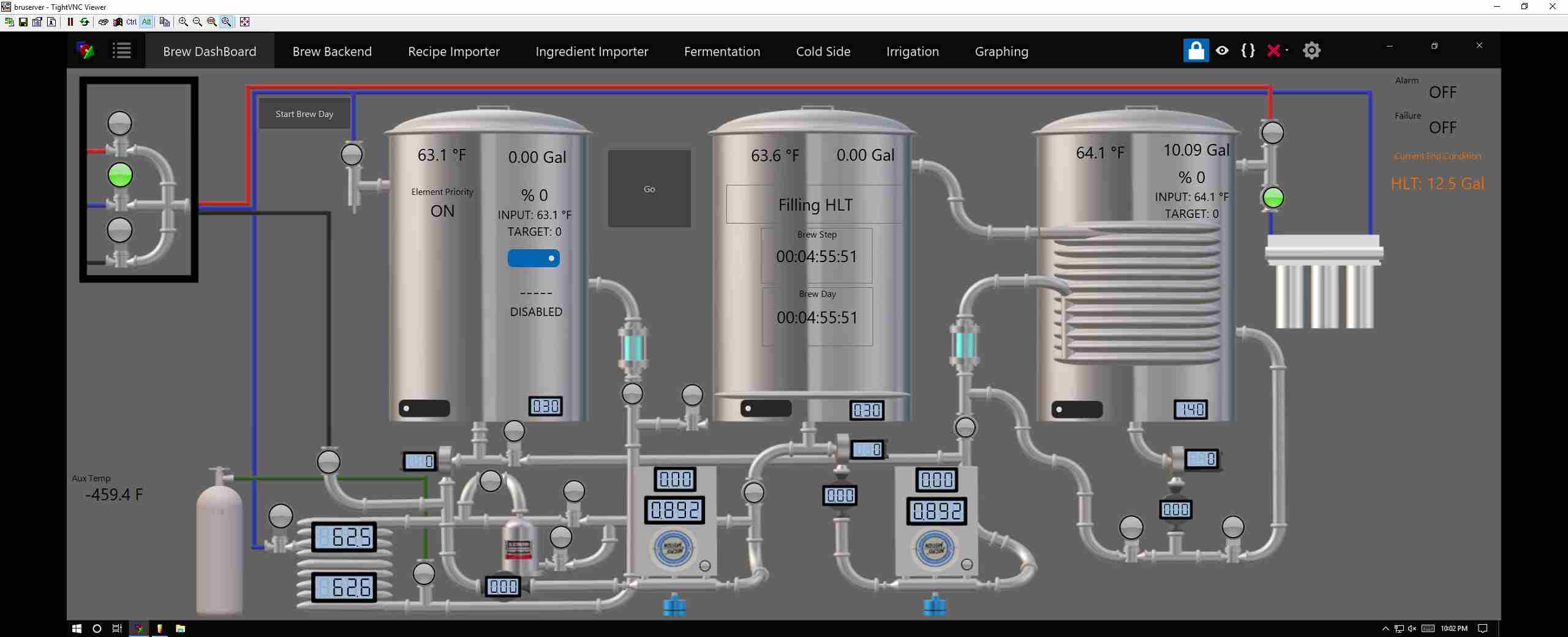
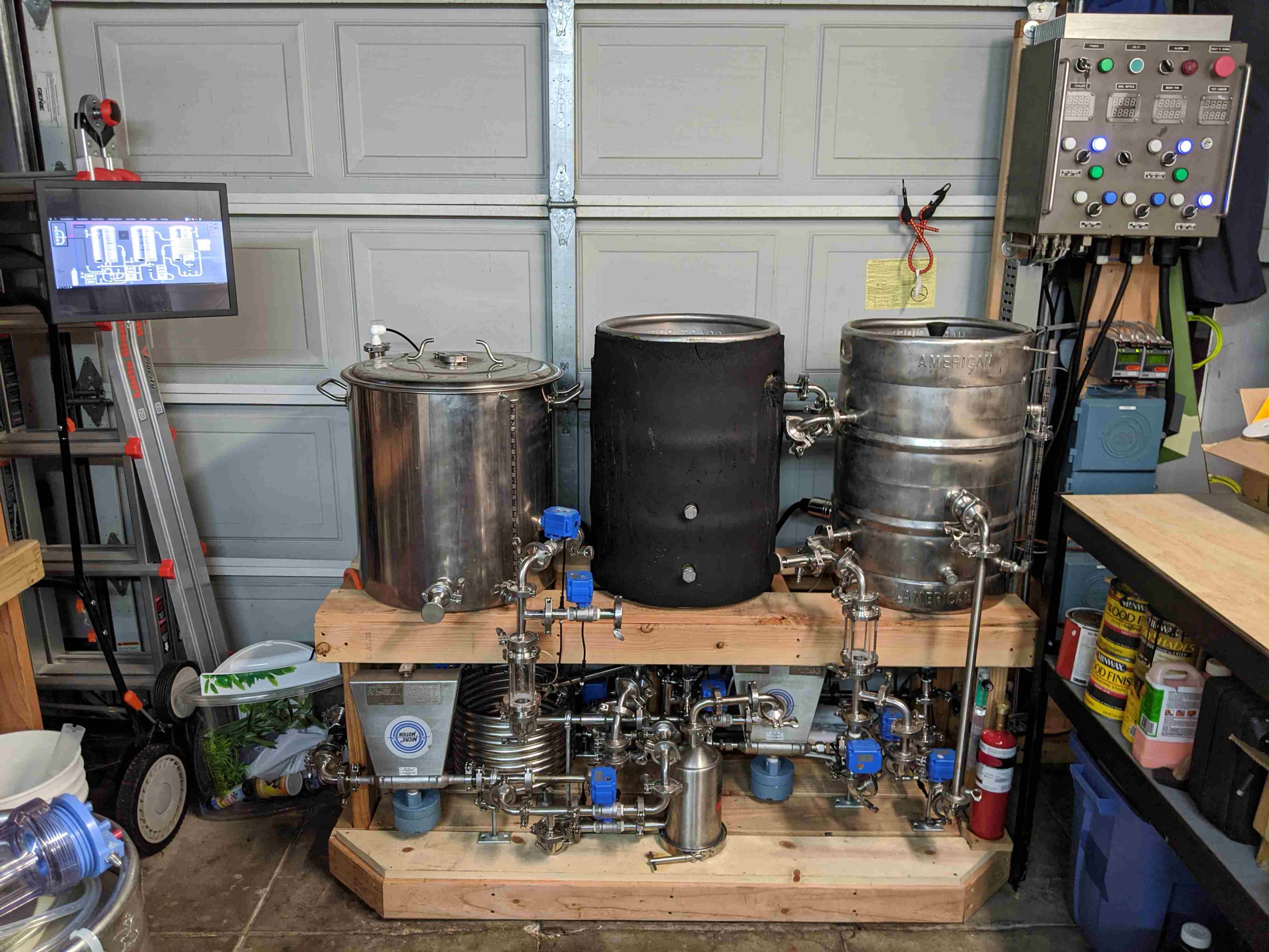
After too many moons, the maiden voyage on my newly upgraded rig is under way. We are filtering RO water over night and will wait until I wake up to start heating the strike water.

Trying to imitate @Die_Beerery, but don't have as many bells and whistles, yet...

dashboard.jpg
 
Last edited:
After too many moons, the maiden voyage on my newly upgraded rig is under way. We are filtering RO water over night and will wait until I wake up to start heating the strike water.

Trying to imitate @Die_Beerery, but don't have as many bells and whistles, yet...

View attachment 656900


Niec work on your paint! Love your MFM renders. Good luck.
 
Glad to report that we successfully turned malted barley into wort and now the yeasties are turning it into beer. There were a few hickups along the way, but overall it was quite a success. A good calibration run to be able to tweak a few things to hit my numbers tighter next time.


IMG_20191213_224111.jpg


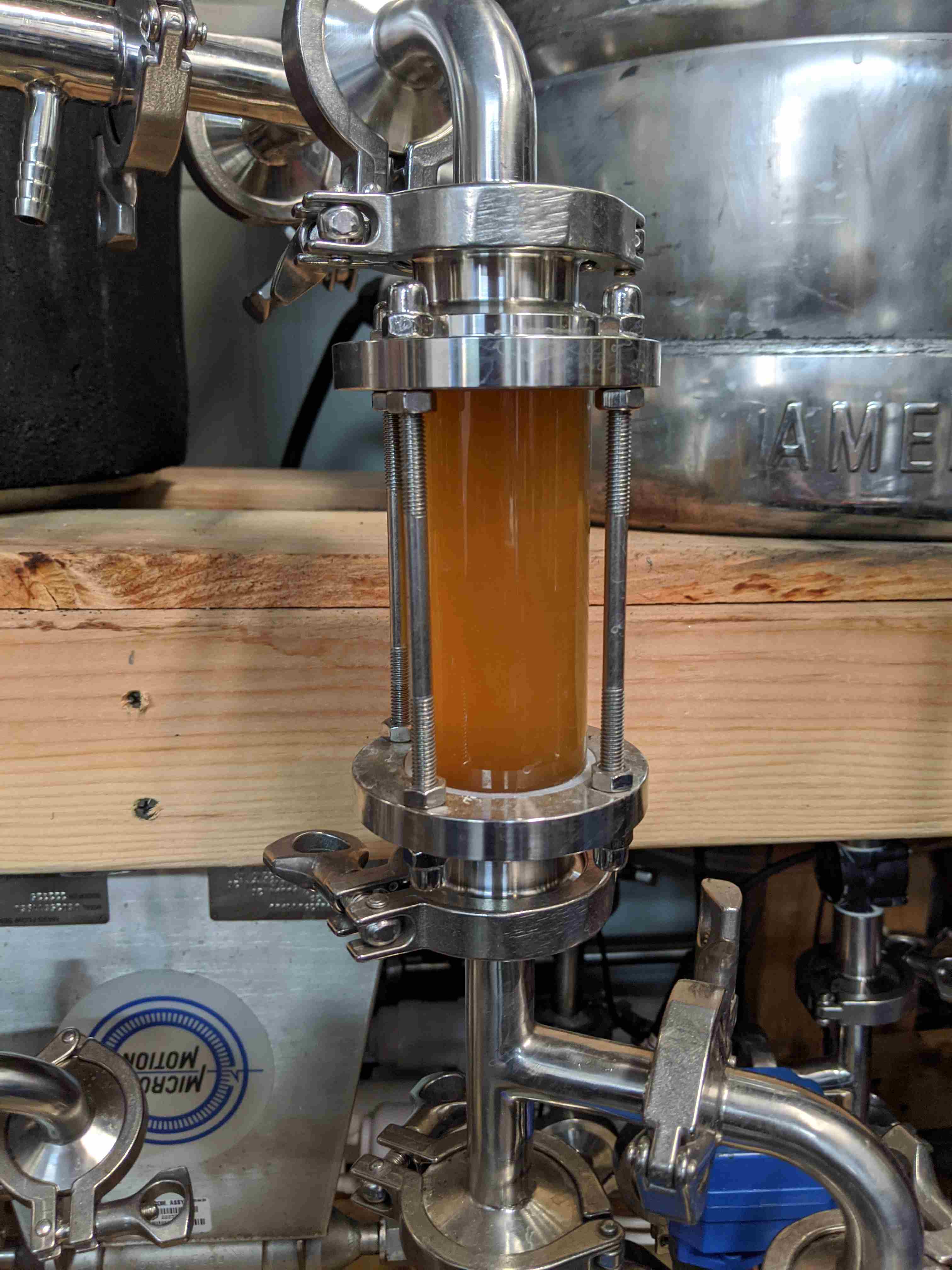
End of Mash before sparging.

IMG_20191214_094733.jpg


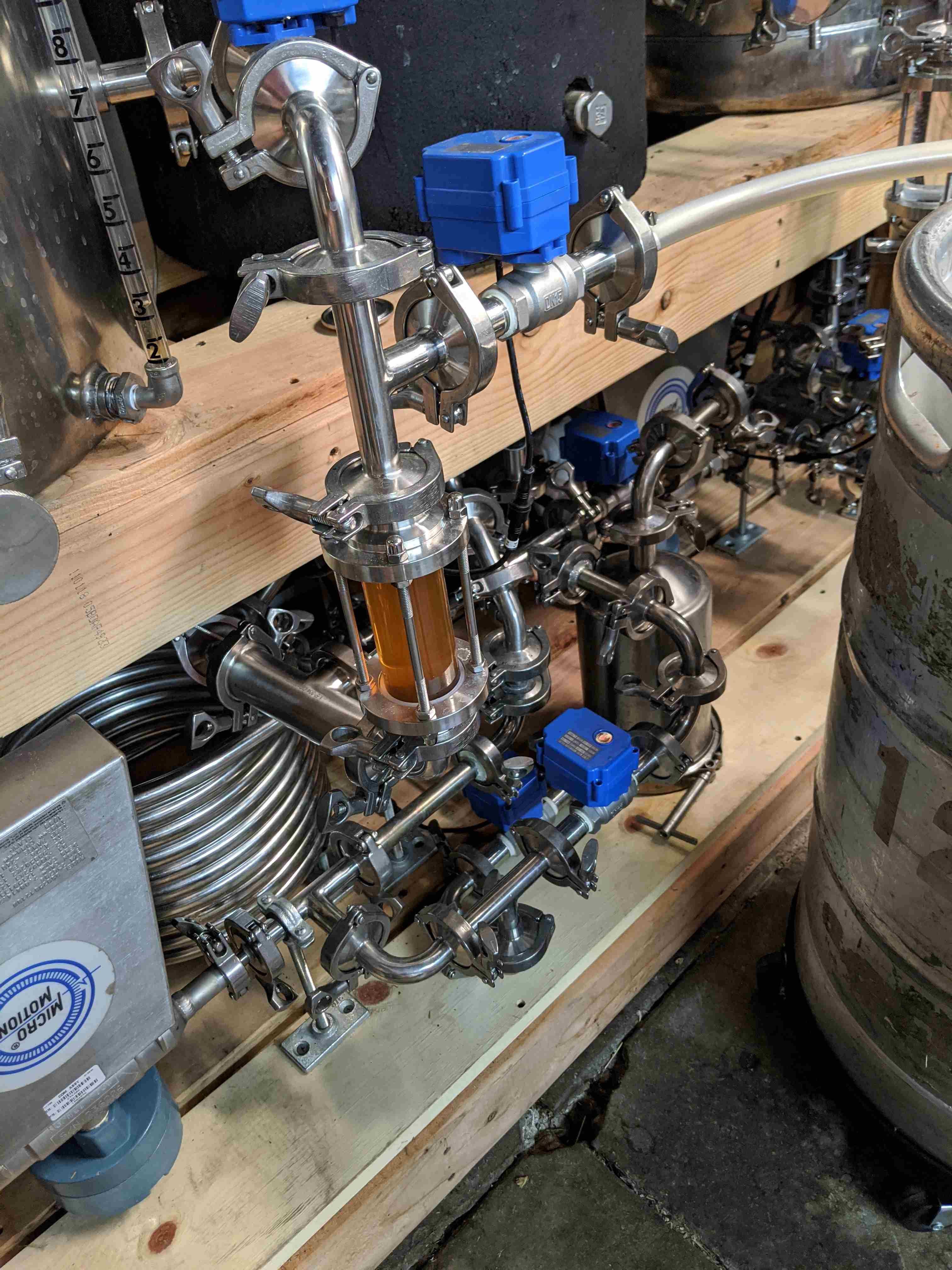
Knock-out

IMG_20191214_162147.jpg
 
I thought I would share my latest hack that might be useful to someone else out there.

I saw some of the Wyze plugs at home depot ($10/each, 9 if you buy it online and pick it up) and got one working in Brucontrol. These are 8266 based, similar to the Sonoff ones. Below is what I did to get it working.

First was to break the base open. These ones are pretty easy, it is just secured around the lip. I squeezed it diagonally in a vice to get the edge to open up and then slid a chisel into the crack to pop it open. Once the edge is released the guts slide right out. Here is a link to a video of someone opening one.


Here is a shot of the module:
IMG_1656.JPG

The whole circuit board can be slid out of the rest of the plastic housing and leads can be soldered onto the back side. The hardest part is soldering on a lead to be able to put the mico into flash mode. This is done by holding GPIO0 to GND, but there is a test point on the board indicated below. I soldered a short wire onto that and used an alligator clip to get it into that mode.
IMG_1655.JPG IMG_1666.JPG

For the data interface, below are the 4 connections I made to go to the FTDI serial chip (3.3v). The signals are labeled in the picture.
IMG_1678.JPG

To program it, I turned it on with a clip lead attached to the GPIO0 wire, and was able to flash it with the BruControl firmware. I tried the both of the 8266 generic firmwares (v45C), but had to use the 8256 version. The other one would dump out some error when it was trying to run when observed through termite.
IMG_1667.JPG

Next I configured the network address and found that it wouldn't work with DHCP (talking to an apple airport express, other NodeMCUs I have work ok) but was fine if I configured it with a static address. I added it as an interface to BruControl and it seems to be happy.
Screen Shot 2019-12-15 at 1.21.51 PM.png

I still need to go through it and see what the IOs are that I can actually talk to, and what GPIO controls the relay, but it looks like there are a couple other ports available too.

I hope this might be helpful if someone wants to incorporate one of these into their setup.
 
I'm just trying to give back to the community :).

I have confirmed that the AD is available and works. I'm going to go through the rest of the pins tonight and map it out. I'll report back with more information.
 
That’s great - congrats!

Looking forward to hearing more details when/if you get time and are willing to share.

Edit: this was meant for @crane. I think Nate and I replied almost simultaneously.
I've been meaning to start a build thread, but I have more important priorities of getting the taps flowing again first.
 
Here is some more information to follow up on the Wyze plugs:

Looking from the bottom of the board, these are the pins that are available to connect to. Looks like all that you could hope for. GPIO12 is the relay control, and GPIO5 is the LED indicator.

IMG_1680 2.jpg

If you want to use GPIO5 for something like 1-wire, you need to disconnect the LED path. I did this by just unsoldering the resistor in series with the LED. I connected a 1-wire temperature probe to it and it seems to work just fine. The resistor that was removed is circled in the image below, but taking the LED off would also work.
IMG_1685.jpg

So that means there are 4 digital I/O and one analog input available with no fuss, and simple 1-wire support. Seems like it could be ripe for mods.
 
I am trying to control a digital out with a switch on two different workspaces.
. It is a logic issue. I can turn one switch true if the other is true, but I also want to turn them both off, if I turn either one off. Any ideas?

As a suggestion, would be nice if we could have a "current workspace" available in the scripts. That would make it easy.

Not sure what you are looking to do... But no doubt it can be done via script.

Also, not sure what you mean by "current workspace". There is a statement 'show workspace “Workspace”' to make the one you want become the active one displayed.
 
You could have a script running (I have a background "housekeeping" thing that watches stuff like that) which has an internal variable. It looks for a change in state of either switch from true to false, or the other way. When it sees a change, it flips both to be the same value.

maybe something like

Code:
new bool current_state
current_state = false

[loop]
if Switch1 State != Switch2 State

//detech which switch flipped
   if Switch1 State != current_state
        current_state = Switch1 State
   else
       current_state = Switch2 State
   endif

//set the states of both switches to the new state

Switch1 State = current_state
Switch2 State = current_state

endif

sleep 1000
goto "loop"

I just tried it out in my sandbox workspace and it seems to work. I do something similar in a few places.
 
Not sure what you are looking to do... But no doubt it can be done via script.

Also, not sure what you mean by "current workspace". There is a statement 'show workspace “Workspace”' to make the one you want become the active one displayed.
I think he is asking for a way to query what workspace is currently active, not change or force a workspace to be active.

However, I'm not sure why you need to know this information to accomplish the desired task at hand. If switch a turns off, then turn off switch b and vise versa. Doesn't matter what workspace is active. Maybe I'm not understanding the desired functionality correctly

Which you should be able to do as well, and I agree I see no point.
 
You could have a script running (I have a background "housekeeping" thing that watches stuff like that) which has an internal variable. It looks for a change in state of either switch from true to false, or the other way. When it sees a change, it flips both to be the same value.

maybe something like

Code:
new bool current_state
current_state = false

[loop]
if Switch1 State != Switch2 State

//detech which switch flipped
   if Switch1 State != current_state
        current_state = Switch1 State
   else
       current_state = Switch2 State
   endif

//set the states of both switches to the new state

Switch1 State = current_state
Switch2 State = current_state

endif

sleep 1000
goto "loop"

I just tried it out in my sandbox workspace and it seems to work. I do something similar in a few places.


Thanks. Works perfectly. I could not figure the logic. I had set up global and was trying to use that as the logic key. the != and using a bool to figure out which was first and then using it to set both is the key.


It still would be nice to know which screen (workspace) had the focus as you could use that in some logic.

sorta like :

if "Workspace 1" focus == true
//then do some code since you are on Workspace 1. If on any other Workspace, code not executed
endif

I have used a "focus" in other programs that provide that property and it can be useful as it is an easy logic tree.
 
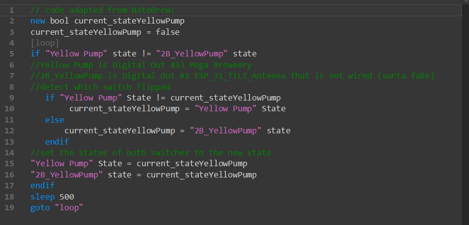
I modified the code after playing with it.

I thought that I could just use the state of the Digital Out instead of a switch. That worked well. I like the way a Digital Out switches "On" and "Off", but not so much for a switch.

I thought: I have some spare Digital Outs on my ESP_32_Tilt_Antenna module that will never be wired due to the location of the device. Could I use a "fake" Digital Out?

It works! If I run out of Fake Digital Outs, I might just add another Mega as they are cheap as I like the On/Off much better than using a switch.

Once we get the "Alias", Both Digital Outs will display "Yellow Pump"!
doublecontrol.png
 
Last edited:
@BrunDog Is there any way to force a PWM pin to be used as a duty cycle in the PID element? I would like to use an ESP8266, which has all PWM pins, to control a fermentation fridge/heater which would need duty cycle PID. I would like to use the D1 mini due to the size and I already have tons of them in hand, lying around. I also would rather not have to script this, as the logic is already built into the base program.

Another note: I listened to the podcast, and you mention a balance of user friendliness and capability. Perhaps, you guys could think about adding "Advanced" interface that would normally be hidden unless the user selects to see it.

Thanks!

You are correct - we did not allow any pins to be digital only. We are planning on making this a setting in the future, but need to incorporate some structural changes in the FW to do it, so it will not be immediate. We'll need to cut a new FW to do this - what is your timeline?
 
So, further chaos with onewire. I had edited my previous post, where I found that my 24VDC pumps were causes havoc with my onewire readings while running (via PWM or just high on the PWM pin). So, I isolated them to a different interface and power. Onewire was solid until, I was doing some testing. On an 8266 interface, I have 2 SSRs hooked up to pins D2 and D4, with my onewire bus on D1. When running the SSRs in duty cycle, everything is fine. However, whenever I drive them via PWM, this is where the issues arrive. It appears that the PWM being generated by the MCU is causing noise/issues with onewire timings. I tried some different capacitors with no avail, and I tried a different 5V power supply to power the onewire sensors, but the grounds have to be tied to the MCU, so the issue persists. I also tried driving floating pins with the PWM, with no difference. SO! It seems that driving PWM signals is causing problems with the onewire network. I wrote a script to lower the PWM output every 5 seconds then reset to 255 when it gets to 0, the two PWM outputs are offset by about 50. When one of the PWM outputs gets close to 0, it causes lots of reading problems, until it resets to 255. The issue is intermittent until that point.

Edit: I am running a slower PWM output loop to see if it is repeatable at certain pwm values. Not sure if this is a electrical noise issue or something that is an internal timer/resource issue.
 
Last edited:
Ugh... sorry. 1-wire just isn’t a strong fit in noisy environment it seems.

Are you testing with 1 sensor or more? Also you mention 5V but keep in mind the ESP8266 is 3.3V. You should be powering it with 3.3V.

Also, try shielded cable. The rest may be layout. I haven’t heard or soft circuits causing noise - only inductive.

The esp8266 pins are 5V tolerant in most cases. I'll try with 3.3V though to see if there is a difference, but I doubt it. I will try shielded cables.
 
I find this interesting, since I have many 1-wire lines running and haven't seen any problems. I use them with 8266s and SSRs and relays. One thing you can do is to power the 1-wire temp sensor (I'm assuming one of the DS18B20 type) with 5V but tie the pull up resistor to the 3.3V rail so that the 8266 gets the right input voltage AND you get the higher power supply on the sensor.

Where are your pull up resistors with relation to the micro and sensors (sensor end, micro end, etc? If you put a local decoupling cap on the sensor, which end was that at? Can you put it at the sensor?

I also have snubbers on my AC things (ssr / relay). Maybe that is helping.
 
@NateBrew what length cables are your onewire sensors on, and how are they wired and connected to your board?

On mine, each DS18B20 is on a 3M cable, connecting to a connector bus, where I have a 2.2K pullup and a 10uF cap (across +/-). As I pointed to in my previous post, this is a star network, which is less than ideal per the resource page. I will probably try to rewire so that I have 1 connector at the box and the rest tie into a main cable. I have tried decoupling caps at both ends, and multiple different values. Does not seem to help.

edit: I also do not have any power going to the output side of the ssrs.

edit 2: @NateBrew Are you using PWM signals with those 8266? My problem is only when a PWM is driven, it works with a duty cycle, no problems. Also, the 8266 firmware is bugged for PWM as it is 10bit and Brucontrol uses 8bit (and caps at 255), and the firmware does not define a new range. So, pwm will only actually be able to get to 0-255 of 0-1023.
 
Last edited:
I have 3 sensors in the main box, each on a 3m long cable in a star. The center of the star is the row of connectors in my control box which has a cap and resistor located on the first connector. There is a single 0.1uF ceramic cap and a 5k resistor (I'm not exactly sure what I used, about 5k though). However, all of that stuff is on the Mega. None of that wiring is shielded.
Edit: From the center of the star, the wire runs up the side of the box about 2ft to get to the Mega. Outside of the box, those wires run in a bundle with all the other stuff zip tied together. That doesn't include the AC power, those are outside the bundle.


I have 2 8266s that have 2 sensors each on 2m long unshielded cables. However, I am using duty cycle control so maybe it doesn't apply.

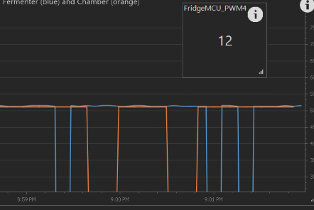
If you have a minute, can you create a PWM output on an unused pin on one of your 8266s and then set it to 12, and check if you get problems with the onewire sensors?
 
Sure enough, one of the sensors dropped out. Those are probably the ones on the shortest lines too.

Screen Shot 2019-12-16 at 9.02.00 PM.png


Edit: Somewhat interesting, the effect persisted after I deleted the PWM device. Does Brucontrol stop the function on a pin if you delete the element? After I reassigned GPIO4 to be a digital out set to 0, it stopped.

Edit2: I tried changing the GPIO that I'm using for the PWM and it didn't seem to matter. GPIO2,4,15 all did the same thing. If it was a coupling thing I would think that 4 would be the worst but they seemed to be identical in their trouble making.
 
Last edited:
@NateBrew Interesting! I unplugged everything from my 8266 and turned off all other devices in my panel, and just plugged in 1 onewire sensor, and the issue is still there. This makes me think it is native to the firmware or hardware of the 8266. I wonder if this issue happens with other boards. I will try to recreate it with my MEGA. It is also interesting with the persistent behavior after deleting the element. It seems that it never sends a "reset" to that pin on the MCU.
 
I tried the test on the Wyze smart plug (8266) that I posted about a little earlier on the thread, as well as the ESP32 I have running my keg fridge.

The Wyze showed the same problem, and even after I deleted the device and made the pin a static digital out, the 1-wire still no longer worked.

The ESP32 seems unaffected by the PWM output running.
 
Last edited:

Latest posts

Back
Top