PSA: Try Powering Your Uncooperative DS18B20s Via 5V

Homebrew Talk - Beer, Wine, Mead, & Cider Brewing Discussion Forum

Help Support Homebrew Talk - Beer, Wine, Mead, & Cider Brewing Discussion Forum:

This site may earn a commission from merchant affiliate links, including eBay, Amazon, and others.

kdw2pd

Well-Known Member
Joined
Dec 27, 2013
Messages
202
Reaction score
39
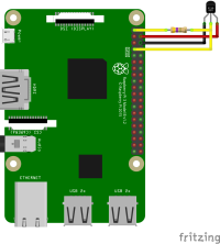
I've been struggling with getting a Pi 4B to recognize some cheap Amazon DS18B20s. I was powering them via 3.3V, and getting the "00-80000000" result in /sys/bus/w1/devices. After scrounging a bit, I found a few references to folks powering them via 5V. Tried it out, and voila, "28-", reading temps, and CraftBeerPi has a kettle sensor once more. So I figured I'd throw this up here to make it easier for someone else to find in the future.

Attached is a wiring diagram of what worked for me (source: A DS18B20 with 5v - Raspberry Pi Forums). Make sure to include the 4.7K pullup resistor between 3.3V and data.
 

Attachments

  • Rpi DS18B20 5V Wiring.png
    Rpi DS18B20 5V Wiring.png
    89.4 KB · Views: 0
Congrats on figuring this out, I've been prescribing it on our numerous controller threads for years :)
Also, you can use up to a 2.2K ohm pull-up resistor when referencing it to 3.3V, which can be handy for long or multi-dropped topologies...

Cheers!
 
Now ya tell me! I looked quickly through a couple of HBT CBPi threads and didn't see that!
 
You'd want to look in the threads for RaspberryPints and especially BrewPi and its derivatives.
Not the most active these days, though, so having it just pop up in recent conversation isn't likely anymore...

Cheers!
 
I would not put 5 volts onto a Pi IO pin.
I had the same issue when using 4k7 pull up resistors on 3.3 volt microcontrollers.
Reducing the 4k7 to 2k2 resolved all the problems while keeping the DS18B20 supply at 3.3 volts
 
You're missing what's going on: the DS18B20 gets its VCC at 5V, but its output is OPEN DRAIN so it cannot drive high, it can only PULL DOWN - it can only assert a "0" and relies on the resistor pull-up to provide a "1". That pull-up resistor in turn is referenced to 3.3V - the same voltage as the RPi VCCIO - so no damage can occur.

Cheers!
 
you are quite right,I looked again at the diagram and see that.
I assumed the pullup resistor was also connected to 5v supply which would have put 5v onto the IO pin.

Cheers
 
Back
Top