Automated HERMS system

Homebrew Talk - Beer, Wine, Mead, & Cider Brewing Discussion Forum

Help Support Homebrew Talk - Beer, Wine, Mead, & Cider Brewing Discussion Forum:

This site may earn a commission from merchant affiliate links, including eBay, Amazon, and others.
Why not take one of your electric NC valves and hook up a Co2 gas line with a low pressure gauge and regulator, pressure up on a couple valves to find the pop open threshold psi of a couple valves? Deduct the pressure of the liquid drop heigth to the valves to get this threshold limit then stay below it with a added safety margin preventing any possible flooding problems. This isn't rocket science. BTW a super looking rig with those valves, I didn't read this whole thread, whats the specs and cost of each electric valve, the voltage AC or DC and the current draw?
 
For the weldless fittings I go :

Female threaded component (e.g., half coupling) - SS washer - keg wall - Silicone O-ring - Locknut - female threaded component (e.g., ball valve)

If you size the hole properly (close fitting) then this arrangement will give you leak free service and a completely solid connection. I have never had a leak that way and my fittings do not wiggle at all.

I would machine 1/4" thick washers with a counterbored pocket to lock in the "O" rings plus allow for plenty of "O" ring pre crush, after machined radius bend the washers in a press or vice with a set of radiused dies that match the kegs radius. This way you can lock down to 70 ft//lbs for a solid leak free connection for no future worries, leaks or loose turning fittings. The best way before going to Tig welded fittings. JMO.
 
Progress update!

We have been working for the past few weeks on the brewing system to get it up and running. We are back in full swing and moving along nicely.

We have the hurricane burners plumbed and wired up and firing!
http://www.youtube.com/v/8w1jkHr7DUw&hl

Thanks to some forum members we were able to drill out the incorrect 1/16" propane gas valves to 1/8" and get them working properly. We also were able to wire up the 24v AC transformer to properly electronically trigger the gas valves.
drillpress.jpg


Pilot Lights lit!
s1.jpg


We are currently working on all of the electronic connections.

Custom valve connection cables
s2.jpg


Custom 1/8" jack mounted inside solonid valve
s3.jpg


And on a side note... our hops have sprouted!!
hops6.jpg

hops7.jpg


Tonight we are finishing up the valves and mounting more fun stuff in the electrical box.
 
We did a number of things last night. We installed the 1/8" jacks in all 10 of the valves, now we have a direct connection from each valve to our control box. We also got in the nylon standoffs and were able to mount a good portion of the electronics in our enclosure. On with the pictures!

Here is a picture explaining the electrical box layout and connections. Their will be a few more than shown here but you get the idea... AC and DC are as separated as possible.
s4.jpg


Here is some other shots of the box from the sides.
s5.jpg

s6.jpg

s7.jpg


Here is a picture of how we modified the stock solonids to have built in 1/8" mono jacks to make them modular and less bulky.
s8.jpg


And here is a final shot of all 10 solonids completed.
s9.jpg


Thats it for now. Going to do some more wiring in the box tonight and test all of the valves. We have 1 out of the 3 PCB boards we need to create ready to etch. Just bought a whole bunch of connectors to use in creating the boards. Again, everything will be modular and replaceable/upgradeable. Working on the board designs the rest of this week and hopefully etching this weekend.

Still left to do is mount the switches/LED's on the front cover. Thats going to take some extensive and careful drilling and soldering. should be fun.
 
Very Nice Work!!

Just curious, are you using the 120VAC or the 24VAC valves? If 120, do you think the 1/8" jacks will handle the voltage? I'm about to wire up my beast and I like the idea...

Thanks,

Bryan
 
Very Nice Work!!

Just curious, are you using the 120VAC or the 24VAC valves? If 120, do you think the 1/8" jacks will handle the voltage? I'm about to wire up my beast and I like the idea...

Niether. We are using 120vAC for the pumps, 24vAC for the Gas furnace valves, and 12vDC for the solonids for the liquid valves. It was hard to find 12vDC 1/2" SS liquid valves for a decent price let alone find them at all. We wired the cables ourselves so they can handle the 1-2A that the valves need instead of using an off the shelf mono wire. We spent a lot of time debating and looking for the right connectors that would hold up and prevent plugging the gas valves into the liquid valves etc. We went with DC barrel connectors on the other end as they come in many sizes and are fairly robust.
 
We got our 1/2" copper coil from NY Brew Supply a few days ago, they custom built it for the specs we gave them.

Shinny.
s10.jpg


We were able to easily install it with the Swagelock fittings. Just press in and tighten down the nut. No dammage to the copper and looks like the fittings alone will hold it in place.
s11.jpg

s12.jpg


We also bent 3 dip tubes out of the scrap 1/2" SS coil we attempted ourselves. The dip tubes came out much better. Here you can see the boil kettle with the dip tube entering the false bottom.
s13.jpg


Just a few short return tubes to make for the upper returns and we are done with tubing. We also were able to clean up the brewery as it has been a bit of a mess after working on this project for the last few months.

s14.jpg


More fun stuff happening this week.
 
http://www.nybrewsupply.com/

They show 50' of 0.020" wall thickness SS but no mention about any coiled chillers just in copper. This I must ask about.

Yes, I talked to Jeff there and asked him to do a SS 1/2 coil for us. He said that with the form they use etc the SS kinks easily and they could only go up to 3/8" for SS coils... All of our fittings and tubing are already 1/2" so we went with copper. We can always upgrade in the future if we can find something else. Other quotes we had were in the $400-500 price range for custom tube bending. Jeff was really helpful, got us exactly what we needed, and shipped it out the next day. The cost was similar to the immersion coolers they sell.
 
Wow not cheap at all. I'll take a visit to my custom fab shop friend he does 90% of his work in stainless. He has many custom built benders and equipment, i'll have to buzz this one past him and report my findings.
 
As you know its summer and brewery tours and what not tend to get in the way of progress. Alas, we are back on track yet again.

Doing some serious work on the electrical side of things. Finally finished and finalized the PCB design and it is ready to etch. If all goes well we should have etched boards by tonight. The rest of the week will be prepping the boards by cutting them to size and populating them with components. Also need to replace the computer PSU that died, new one is ready and waiting to go in.

Here is the control box with all of the airplane switches mounted. Can you have too many airplane switches? I think not!

switchbox.jpg


Everything is designed to be modular, this way we can swap out/upgrade/replace anything in parts rather than the whole board for this stage. Also separates AC and DC boards.

While were etching we are also going to do the boards for the RFID reader door lock so we can get rid of the bread boards!

At some point we also installed a 4 camera network security system. This serves a dual purpose of being able to monitor things in the brewery as well as being able to broadcast a live feed on the net when we are brewing! No camera setup, just flip a switch and we are live! also its recording 24/7 so we can always grab footage later and do stuff with it. Should make for some interesting videos.

More updates coming as we work on the boards this week!
 
As promised more updates!

Finally got around to etching the circuit boards. Still not 100% sure they will all work or all of them turned out good but from what I can tell everything looks good. Also threw in the boards for the RFID lock reader for the brewery while I was etching anyway.

Instead of spending $100+ on a UV PCB exposer I bought two cheap clip on lights and 2 UV black light CF bulbs which was about $20 total. Worked great.
s15.jpg


Here you can see the circuit traces printed on transparency paper over the PCB board being exposed to UV light.
s16.jpg


After exposing to UV light you rinse the board in a chemical that washes off the excess plastic leaving only the traces covered in plastic.
s17.jpg


Then the board goes in etching bath where all exposed copper is etched away leaving only the nice copper traces. This is the RFID reader board done as a test piece first.
s18.jpg


Here is the larger board where I did all of the smaller boards at once.
s19.jpg


The boards were all cut apart and trimmed up. I then used this handy guy to drill out the holes for the components
s20.jpg


Here are all 5 of the finished boards. Most are labeled. From top to bottom, Left to right, the Hub, which collects the signals from sensors and all valves and relays etc and combines them into one 26 pin cable. The AC relay which takes 5v inputs and triggers the 24v AC for the gas valves and the 120v AC for the pumps. The DC relay board which takes 5v inputs and triggers the 12v dc for the liquid valves. The controller for the RFID board. The reader for the RFID board.
s21.jpg


AC relay board populated with Solid State relays ready for testing.
s22.jpg


Hoping to finish up the rest of the boards tonight and do some testing. If we get anything functional there will be videos to follow!
 
Time for some serious updates....

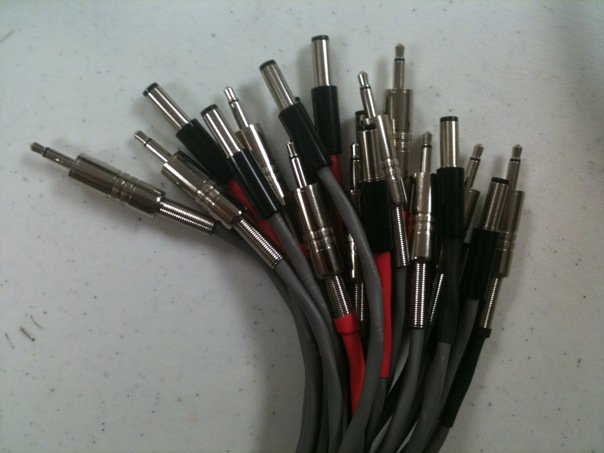
After soldering, crimping, splicing, stripping, twisting, and electrocuting my self once, I am happy to say that we have finished the basic prototype electronic control for the brewing system.

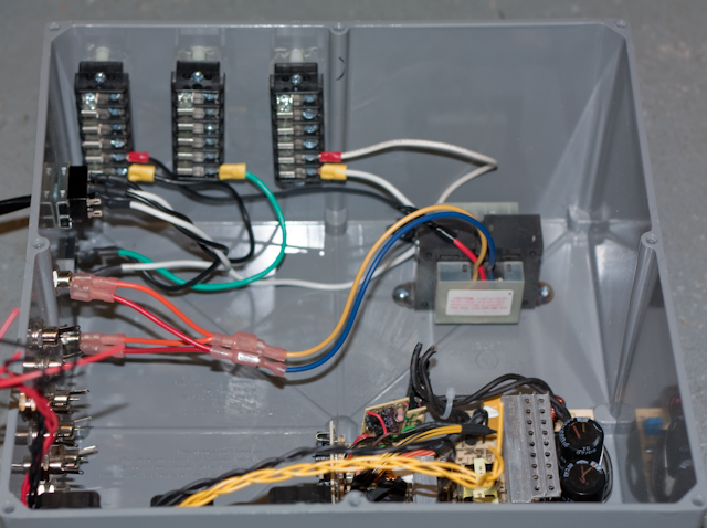
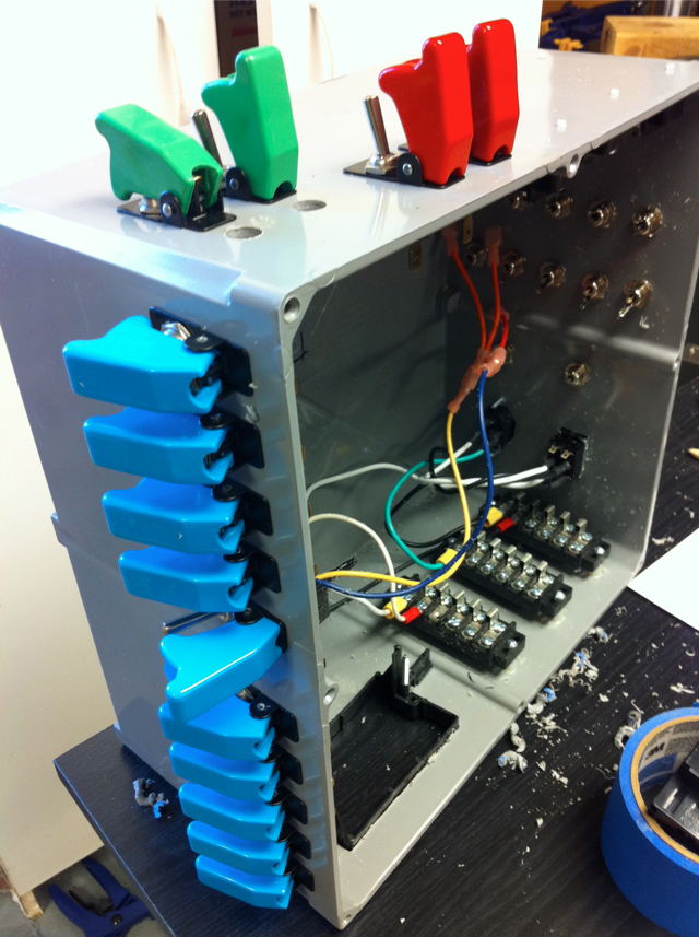
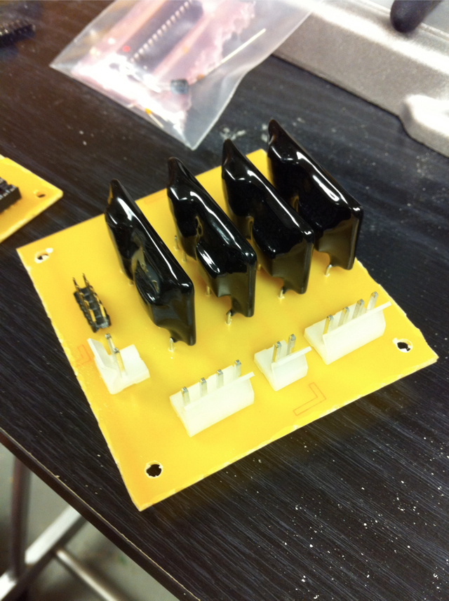
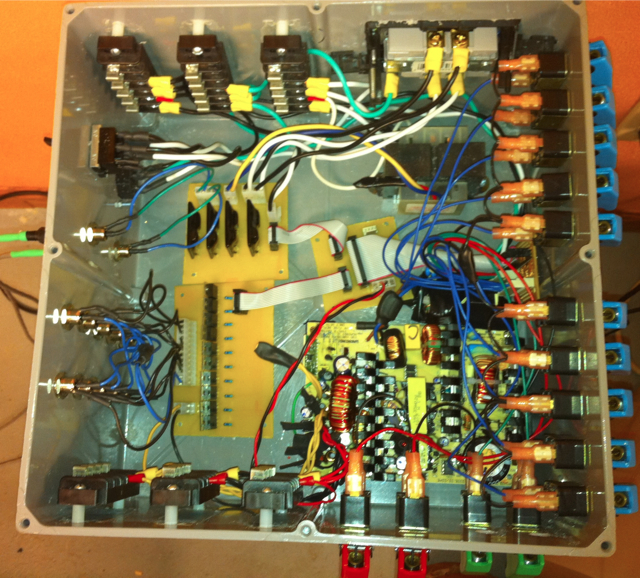
What we have now is a 12" x 12" box which houses all of the electronics necessary to control all of the pumps and valves for the entire system manually with toggle switches. This system is currently setup in such a way that it is very modular and as we find any flaws or ways to enhance the system we can swap out parts and replace them easily.

The system is also setup in such a way that the switches that control everything are really sending 5v signals, not doing actual switching of the actual voltages. This will make it a trivial task to have a micro controller replace the switches and control everything by itself.

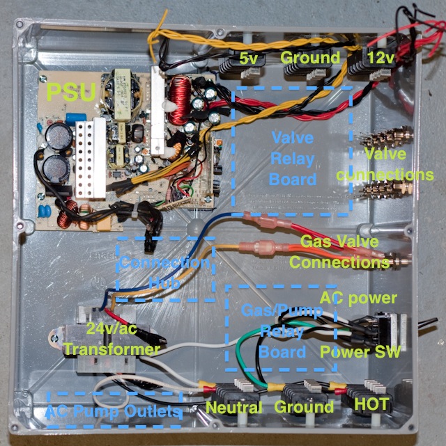
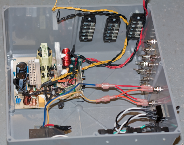
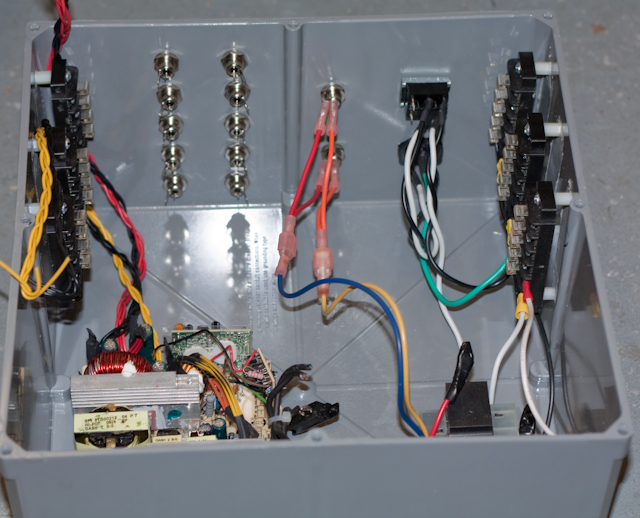
Here is a picture of the control box.

s23.jpg


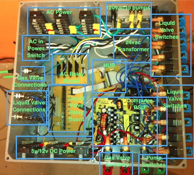
And here is all of the sections labeled.

s24.jpg


And here is a more detailed video overview of the system and a quick explanation of how it works.


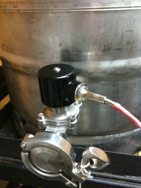
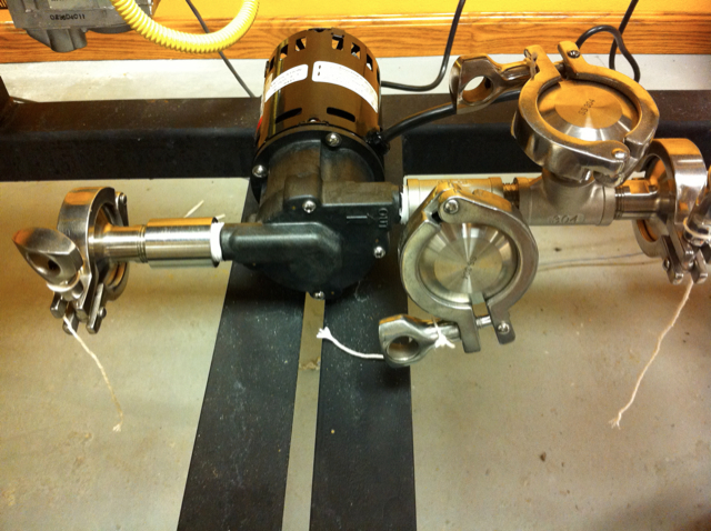
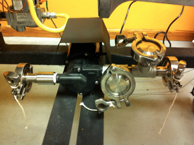
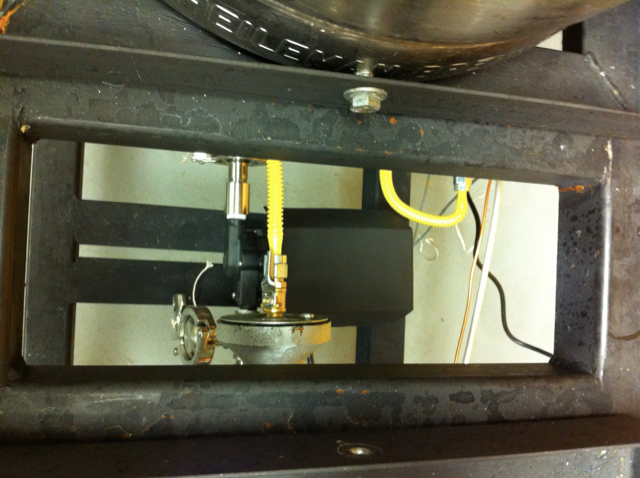
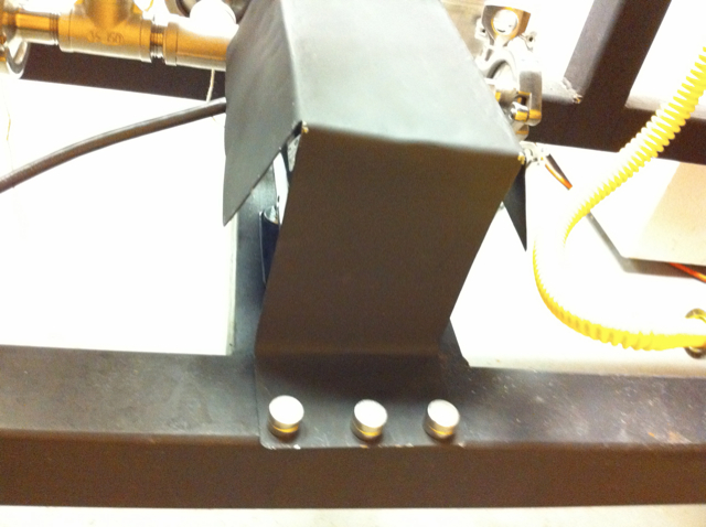
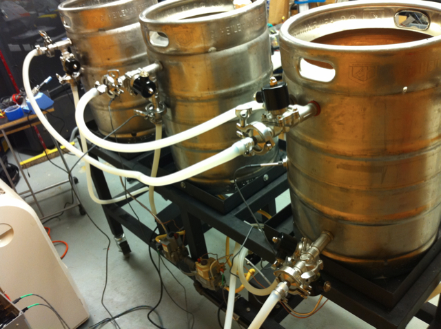
We are bolting down the pumps tonight and testing the pumps burners and valves at the same time. If they are working we should be ready to do some more extensive testing and move on to some test batches soon.

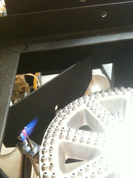
Here is a video of the control box turning on and off the two burners via the red switches.


Thats all for now. When we have more parts connected together we will show some footage of everything working together.
 
Last edited by a moderator:
Last night we bolted in the pumps to the frame.

s25.jpg


Then we tried out the newly fabricated Pump Shields our welder Adam made for us.

s26.jpg


Here is the view from the top. You can see any spills will now not fall into the motor of the pump.

s27.jpg


How did we attach the shields? Magnets! Easy to install, service, and remove etc...

s28.jpg


Going to attempt to test out at least one circular path using a pump, valves, and lighting a burner and see if we can do a test boil tonight. Their will be a video up if everything goes well.
 
For some reason something wonky is going on with the transistors for the 12v DC relays. Going to do some in depth testing tonight and see if I can resolve the issue.

Just ordered some Tri-Clover to Barbed hose fittings from BrewersHardware.com. It turns out the 7/20 fittings we have are 1/2", which makes sense.... since we are using 1/2" tubing... but the actual inside diameter is 0.38" which was creating a sole choke point in our 1/2" system. So we ordered 3/4" barbed fittings which has a 1/2" internal opening that matches up with the rest of our fittings.

If we can get everything straitened out we should be able to do a full systems test with both burners, both pumps, and all of the valves etc. this weekend.

Here is a video of a pump, valve, and burner in action at the same time.

 
Last edited by a moderator:
That box is insane!
Although I had to chuckle.
After watching this amazing,complicated build being put together, you decribed a small problem as ..."something wonky is going on:..
 
That is the best word to describe it at this point.... Sometimes it is working.... sometimes not.... Sometimes I can meter the voltages and I get what I expect.... sometimes not.... I suspect cheap airplane switches from ebay are partially the problem as some were manufactured incorrectly and are on when they should be off etc..... Going to try to sort it all out.
 
Figured out why the voltages were "wonky" Apparently the nicer more expensive PSU that we bought has current protection so that you cant just suddenly draw an amp of power through it, it flips out and resets etc. Looking for a solution for this in a separate thread going on here https://www.homebrewtalk.com/f51/help-12v-dc-power-192240/

The good news is that we got our order of nice shiny Stainless Steel 3/4" barbed Tri-Clover fittings we needed to connect all of the high temp silicon tubing to the system.

Huge thanks to Derrin at www.BrewersHardware.com for helping us out again with fittings etc. We bought the Stainless Steel temperature probes you see in all of the kettles, they are fantastic, he also sells some with a collar so you dont whack them when your stirring. He suggested 3/4" barbs for our 1/2" tubing so we would have a true 1/2" flow throughout the system. Here are the 20 our system needed from him.

s30.jpg


Looking at the 1/2" MPT to Tri-Clover fittings on the kegs and the 1/2" barbed fittings you can see the internal opening is less than 1/2".
s31.jpg


Here is the system all plumbed up and ready for some testing!
s29.jpg


And a quick tour around the system with the hoses connected.
 
Last edited by a moderator:
congrats on a SICK build!!! Would you mind letting me know the length and size (I.D.) of your herms coil?

Thanks!
 
We have finished assembly of our new system! Watch below as we run through a few of the brewing steps testing out the connections. Going to do some more testing this week and hopefully a test batch as well. What do you think?

 
Last edited by a moderator:
awesome video!

The young lady in the background looks terribly bored... ;)

I will tell her to smile more next time.... or give her something to smile about.... After hours of melting circuit boards, leaks, and soldering/taping/etc this video was taken. She was the official switch flipper while I narrated (poorly) and shot the video.
 
Looks like once the grains are in, you won't ever have to stand up until the end of the brew day. Maybe you could add a

wheelchair%20accessible.JPG


sign to it.
 
I appreciate the humor but the entire point of the automated brewing system is so that we can brew more efficiently, quickly, less energy waste, and with less people and hassle. This means we can build additional systems and brew multiple batches simultaneously.
 
I appreciate the humor but the entire point of the automated brewing system is so that we can brew more efficiently, quickly, less energy waste, and with less people and hassle. This means we can build additional systems and brew multiple batches simultaneously.

Oh, I get that, any criticism you receive from me stems purely from jealousy of your bad ass system. Some say automation takes the fun out, but I'm with you, automation takes the hassle out and leaves the fun behind. Which is of course just one of the myriad of benefits such as perfect control, consistency, and the others you just listed.
 
Back
Top