Auberins Brew In A Bag Panel (BB-100)

Homebrew Talk - Beer, Wine, Mead, & Cider Brewing Discussion Forum

Help Support Homebrew Talk - Beer, Wine, Mead, & Cider Brewing Discussion Forum:

This site may earn a commission from merchant affiliate links, including eBay, Amazon, and others.

Barron

Active Member
Joined
Feb 17, 2009
Messages
34
Reaction score
1
Location
Minneapolis
Hi everyone,

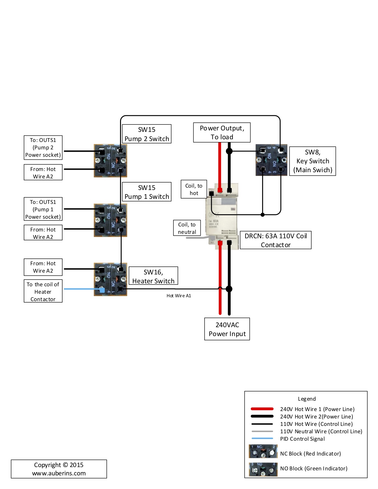
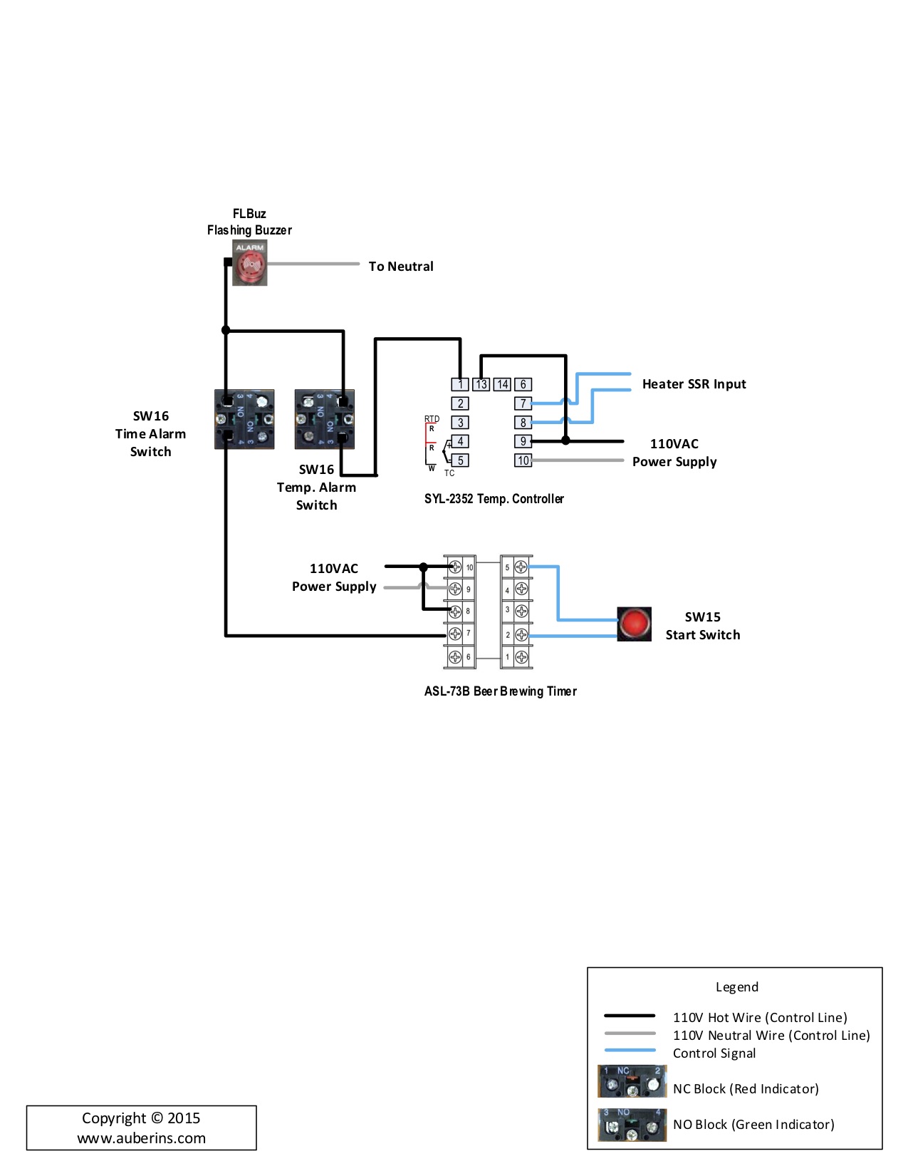
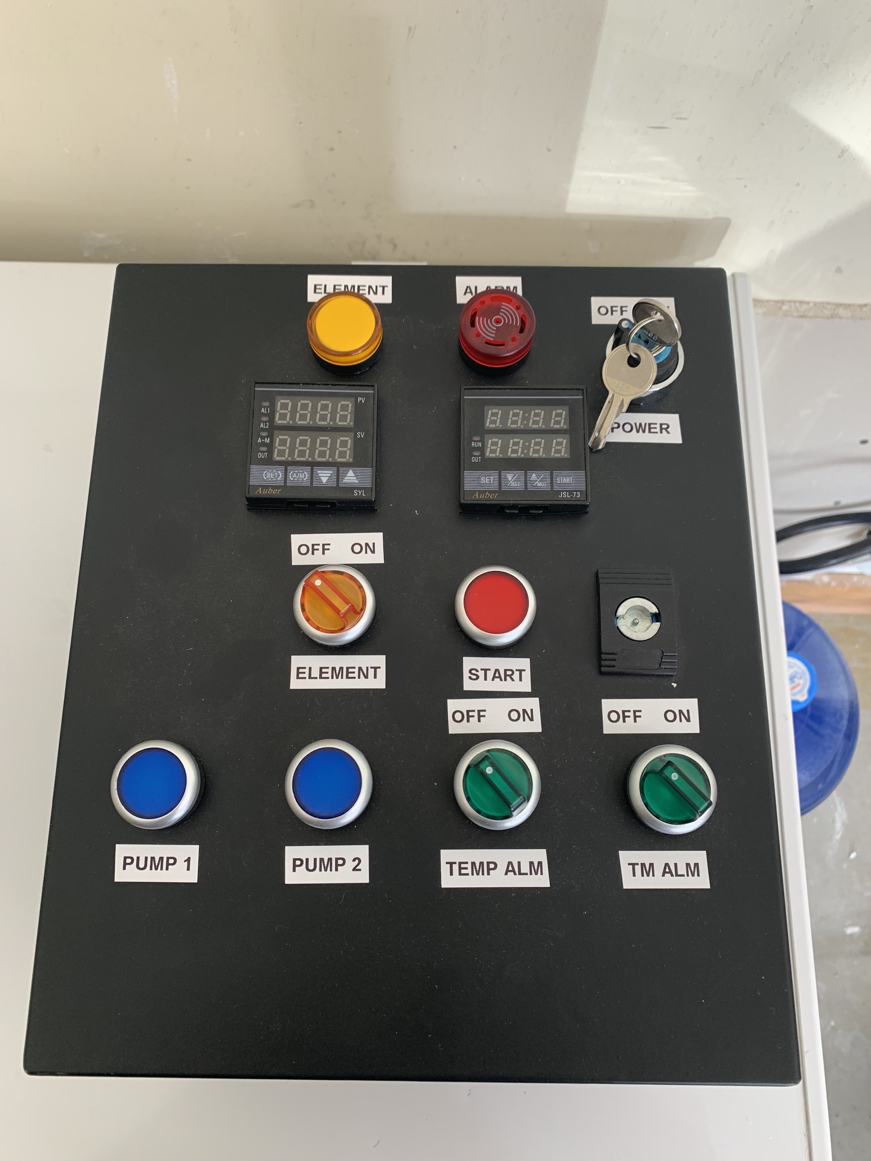
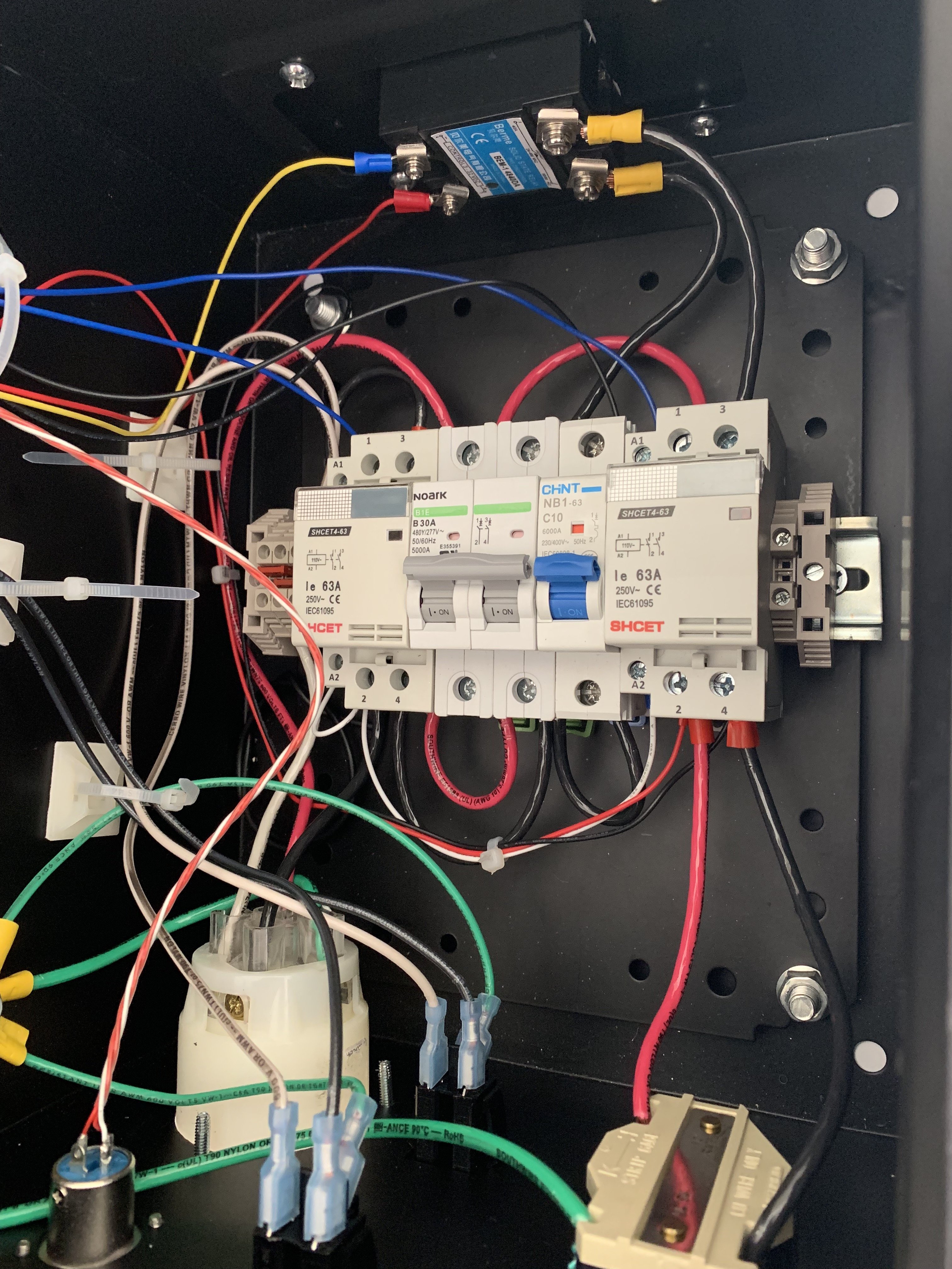
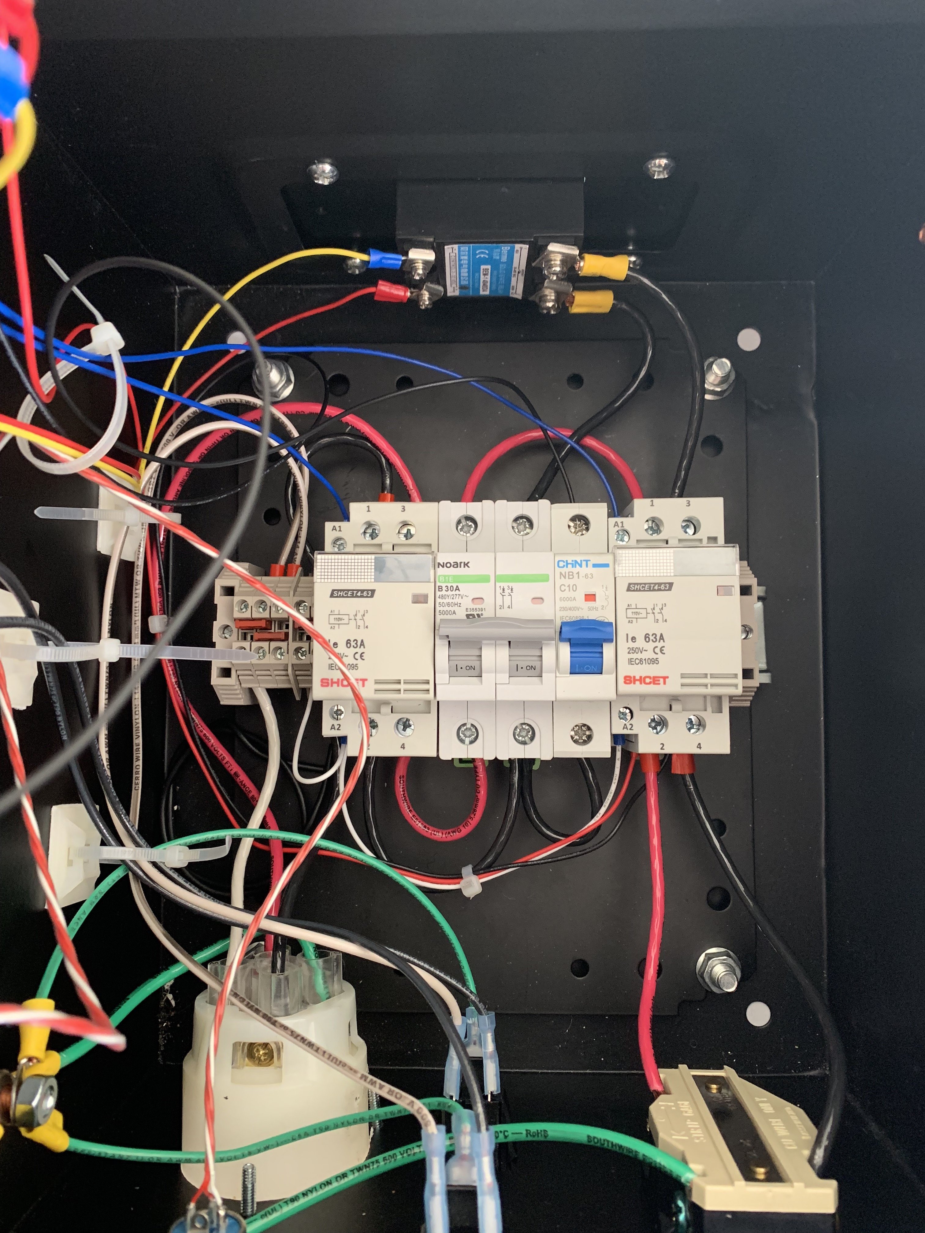
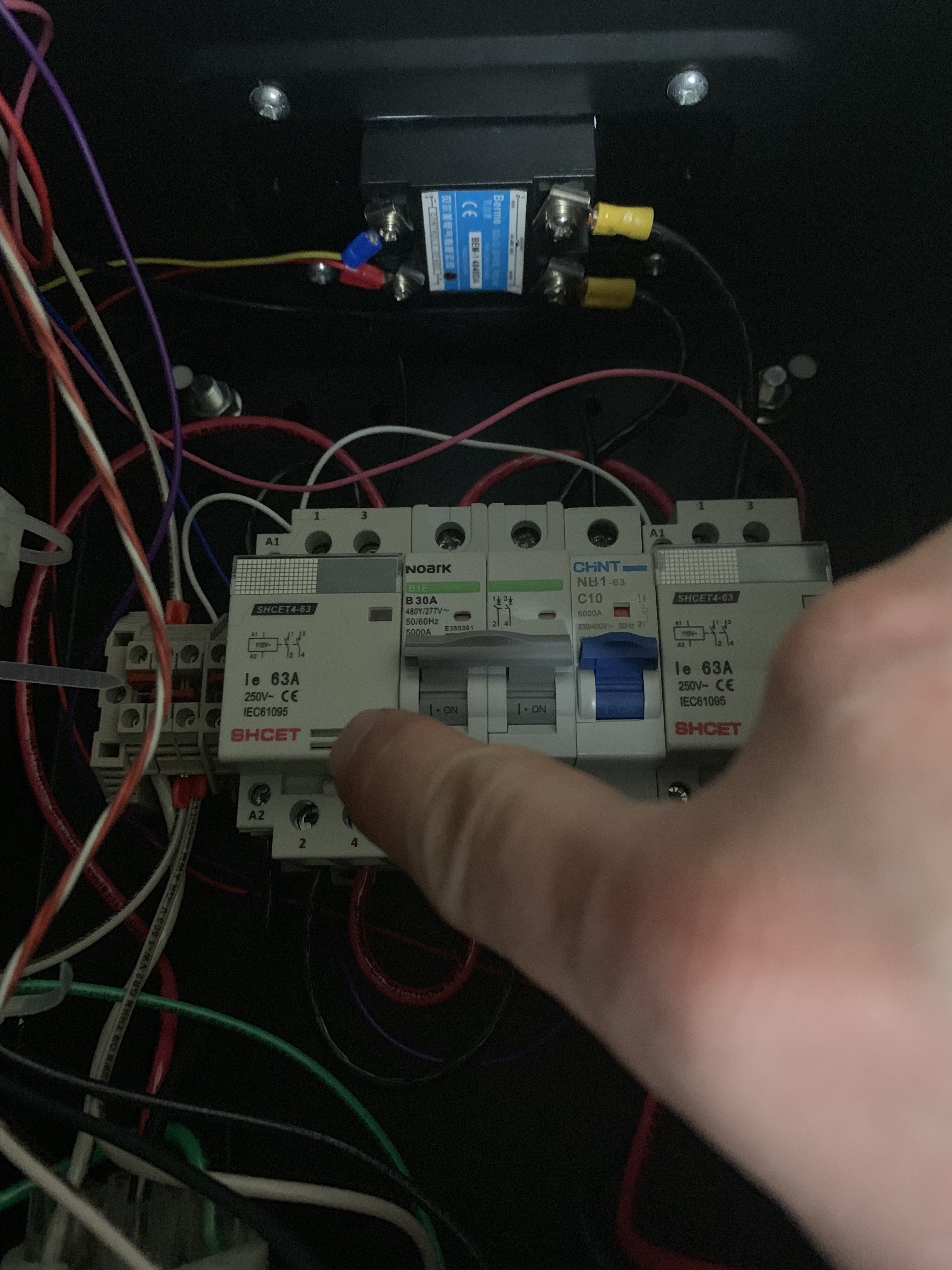
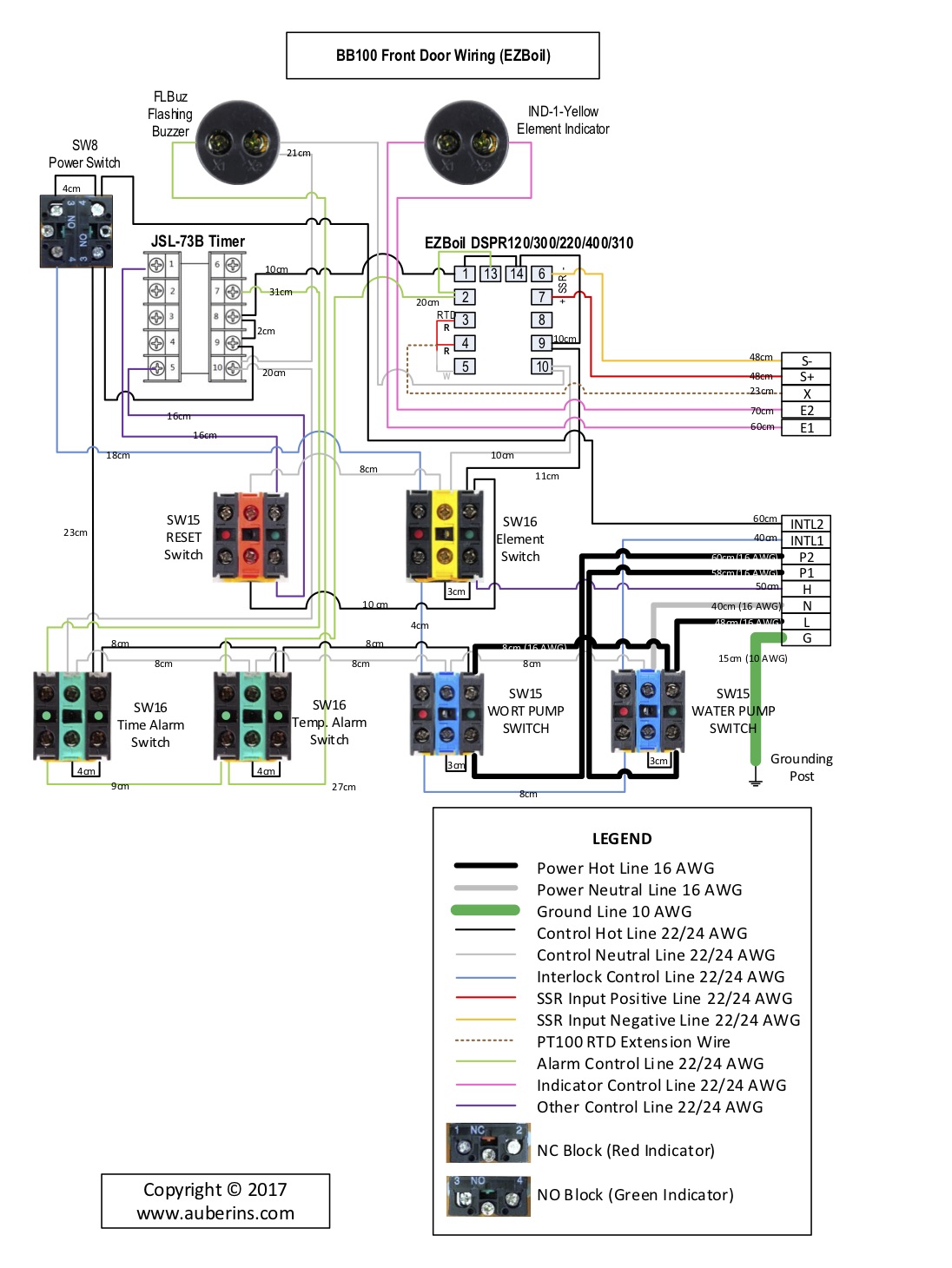
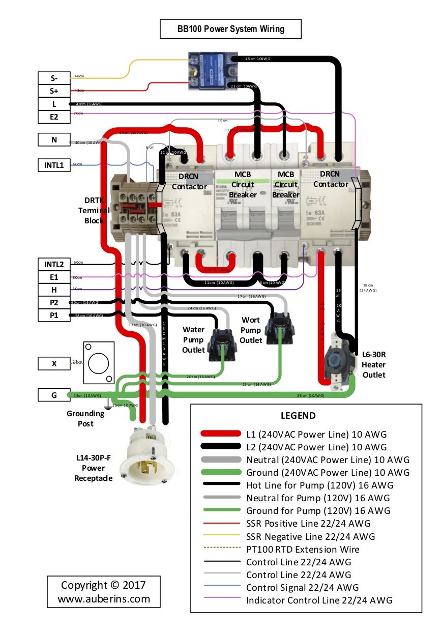
I purchased most of the parts for this control panel back in April of 2016 and have finally started to wire it. Was hoping some you could possibly help me along the way. I'm not very knowledgeable about electric so the diagrams I received are a little confusing. Would anyone be willing to take my wiring diagram and lay it out on one page for me? It's currently on three different pages. I also have different switches than the ones in the diagram so that confuses me a bit as well. I will post pictures of the progress I've made asap.
 

Attachments

  • diagramv1.4.jpg
    diagramv1.4.jpg
    192.8 KB · Views: 189
  • diagramv1.4 2.jpg
    diagramv1.4 2.jpg
    174.9 KB · Views: 212
  • diagramv1.4 3.jpg
    diagramv1.4 3.jpg
    138.5 KB · Views: 188
I can see getting confused on those, but I do like that they integrated safe start into their plan.

@doug293cz has a diagram drawn up that had everything but the alarm/timer section. He might be able to re-share.

The most confusing part on their diagram might be that they flipped the main contactor upside down between diagram 1 and 2. Some better color coding would also really help them out.
Thanks for your reply! Here is where I'm at so far.
 

Attachments

  • IMG_1014.JPG
    IMG_1014.JPG
    1.6 MB · Views: 200
  • IMG_1015.JPG
    IMG_1015.JPG
    2.4 MB · Views: 194
  • IMG_1016.JPG
    IMG_1016.JPG
    2.4 MB · Views: 184
  • IMG_1017.jpg
    IMG_1017.jpg
    2.7 MB · Views: 186
Is there anyone around who could help me out? I'd really like to have this thing up and running by next week.
 
They didn't supply you with a complete diagram, but I have it figured out now. I don't think it's exactly like any of my designs, but I have a bunch that are close. I'll see if I can find one to modify to match this design (which I don't think Auber offers anymore.)

Brew on :mug:
 
They didn't supply you with a complete diagram, but I have it figured out now. I don't think it's exactly like any of my designs, but I have a bunch that are close. I'll see if I can find one to modify to match this design (which I don't think Auber offers anymore.)

Brew on :mug:
That would be awesome! Thank you!
 
Four words: "cable management. Think NASA."

A neat wiring job is a safe and easy to repair wiring job. You wont regret putting some extra effort into dressing your cables.

That's the only constructive thing I can add, other than I am currently wiring up their HERMS 3 vessel panel and it's going slowly but smoothly.

Their customer service has been excellent, since I was sent a defective contactor. They replaced it no questions asked.

I appreciate your constructive criticism.. Everything will be neat and tidy once I'm done wiring. Most of the zip ties are loose just holding the wires in place.
 
Four words: "cable management. Think NASA."

A neat wiring job is a safe and easy to repair wiring job. You wont regret putting some extra effort into dressing your cables.

That's the only constructive thing I can add, other than I am currently wiring up their HERMS 3 vessel panel and it's going slowly but smoothly.

Their customer service has been excellent, since I was sent a defective contactor. They replaced it no questions asked.
I'll be the one to jump in and say that the enclosure looks perfectly safe and easy to maintain in it's current configuration.

We wouldn't have to build a show piece, and we aren't building so that 15 other technicians can work behind us. Safe, functional, and you're fine.
 
I know you are waiting, but getting custom design work for free (rather than $100 - $200/hr) has some drawbacks. I haven't forgotten you.

Brew on :mug:
 
No problem @doug293cz! You were absolutely correct that they didn't give me the full diagram. I emailed Auberins and they sent me a completely different/full diagram. I have everything wired up but when I push pump 1, pump 2 or element the whole system shuts down? Other than that everything else seems to be working properly. Any ideas of what might be causing this?
 
No problem @doug293cz! You were absolutely correct that they didn't give me the full diagram. I emailed Auberins and they sent me a completely different/full diagram. I have everything wired up but when I push pump 1, pump 2 or element the whole system shuts down? Other than that everything else seems to be working properly. Any ideas of what might be causing this?
Is it tripping the GFCI? If not, what is tripping that shuts everything down?

Brew on :mug:
 
Is it tripping the GFCI? If not, what is tripping that shuts everything down?

Brew on :mug:
I dont think it tripping the GFCI. Honestly im not really sure whats going on. It seems like its tripping the contactor on the left that im pointing to.
 

Attachments

  • IMG_2224.JPG
    IMG_2224.JPG
    1.9 MB · Views: 56
I dont think it tripping the GFCI. Honestly im not really sure whats going on. It seems like its tripping the contactor on the left that im pointing to.
Can you post the latest wiring diagram you got from Auber? If the main power contactor is dropping out when other things are turned on, it sounds like something is wrong with the wiring of the "safe start" circuit.

Brew on :mug:
 
Can you post the latest wiring diagram you got from Auber? If the main power contactor is dropping out when other things are turned on, it sounds like something is wrong with the wiring of the "safe start" circuit.

Brew on :mug:
Just dm'd it to you
 
Here is the diagram for others to look at.
 

Attachments

  • KIT_EZBoil_Wiring v2.0.jpg
    KIT_EZBoil_Wiring v2.0.jpg
    277.5 KB · Views: 52
  • KIT_EZBoil_Wiring v2.0 2.jpg
    KIT_EZBoil_Wiring v2.0 2.jpg
    232 KB · Views: 54
First thing I'd check is that you have the main power switch wired correctly:

upload_2019-5-16_14-23-31.png


Note the jumper wire between terminals 3 and 4 on the top of the switch, and the second wire that connects to the main power contactor coming off of terminal 4. If you just have upper terminal 3 connected to the main power contactor, you would get the behavior you are seeing (if I understand your stated symptoms correctly.)

Brew on :mug:
 
First thing I'd check is that you have the main power switch wired correctly:

View attachment 626962

Note the jumper wire between terminals 3 and 4 on the top of the switch, and the second wire that connects to the main power contactor coming off of terminal 4. If you just have upper terminal 3 connected to the main power contactor, you would get the behavior you are seeing (if I understand your stated symptoms correctly.)

Brew on :mug:
Thanks Doug! I'll go take a look.
 
Yeah, looks right. If you have a multimeter (volt/ohm meter), unplug the panel from the incoming power. Then measure the following for continuity:
  1. With main power switch off, measure resistance between the screw tops of top terminals 3 and 4 - should read 0 ohms
  2. With main power switch off, measure resistance between the screw top of top terminal 4, and the terminal screw on the main contactor that connects to the wire from terminal 4 - should read 0.
  3. With main power switch on, measure resistance between the screw top of top terminal 4 and the screw of bottom terminal 3 - should read 0.
  4. With main power switch on, measure resistance between the screw top of bottom terminal 3, and the terminal screw on the main contactor that connects to the wire from terminal 4 - should read 0.
Brew on :mug:
Everything seems to match up. Im begining to think its a grounding issue? the nuts that are on the grounding post dont fit well and all the grounds are not totally tight to the post. Could this be part of the problem?
 
Everything seems to match up. Im begining to think its a grounding issue? the nuts that are on the grounding post dont fit well and all the grounds are not totally tight to the post. Could this be part of the problem?
That's something that should be fixed, but I don't think it is related to your problem.

To reiterate: With the element and pump switches off, you can turn on the main power switch, and the main power relay will engage (should hear a click when it engages. But, if you then turn on any of the pump or element switches, the main power contactor disengages. Is this correct?

Brew on :mug:
That is correct. Here's a video of the panel powered on and this is what happens when i turn the element or pump switches on.

 
Where do the two wires connected to the lower right terminal 3 on the main power switch connect? Please trace the wires, not just tell me what the drawing says.

Brew on :mug:
 
Where do the two wires connected to the lower right terminal 3 on the main power switch connect? Please trace the wires, not just tell me what the drawing says.

Brew on :mug:

One wire comes out of terminal 3 of the power switch to 9 on the timer. The other comes out of terminal 3 to the timer alarm.
 
Well I'm pretty sure I found my problem. A2 on the main power contactor is missing a screw. Ordered a new contactor and it will be here Thursday. Hopefully everything else will work properly after that.
IMG_1376.JPG
 
Unfortunately that was not the issue[emoji53]. I'm not sure what's going on with this panel? Everything seems to be wired right looking through the diagram.
 
I reached out to Auber and they sent me an Interlock troubleshooting guide. Everything was ok except for 1 & 6, they didnt show any voltege. Any sugestions on what might be goin on or what i should do next?
 

Attachments

  • IMG_1500.jpg
    IMG_1500.jpg
    322.9 KB · Views: 36

Latest posts

Back
Top