New 60amp Brew Panel Schematic Review and Question

Homebrew Talk - Beer, Wine, Mead, & Cider Brewing Discussion Forum

Help Support Homebrew Talk - Beer, Wine, Mead, & Cider Brewing Discussion Forum:

This site may earn a commission from merchant affiliate links, including eBay, Amazon, and others.

Slapstik007

Member
Joined
Sep 2, 2012
Messages
9
Reaction score
1
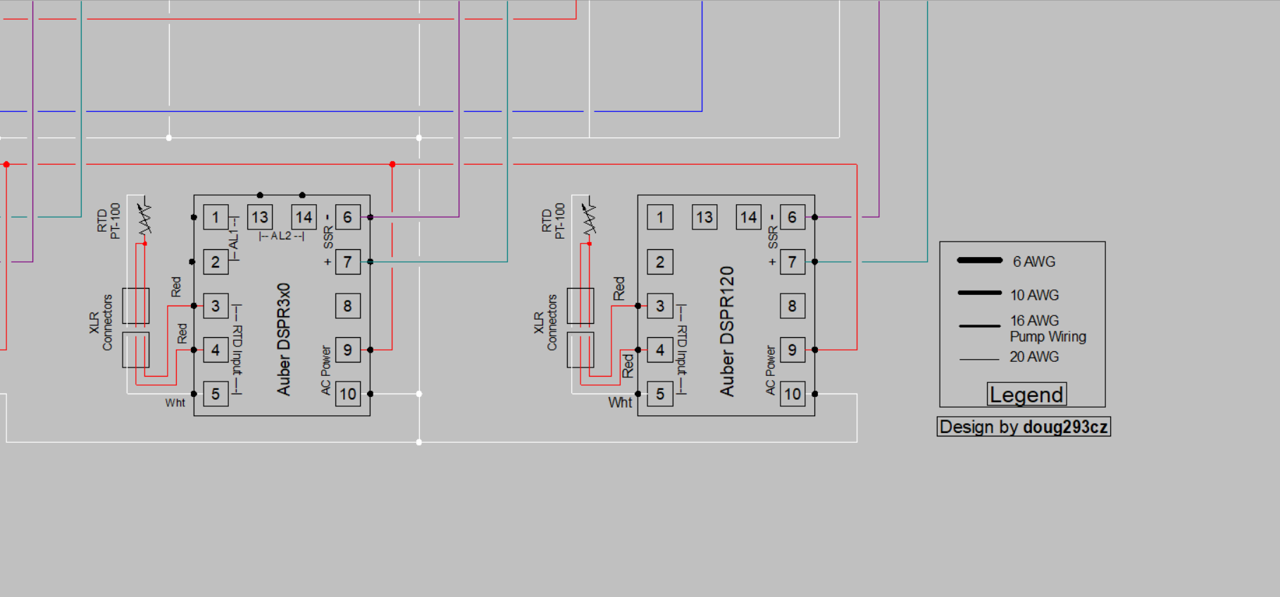
Looking for another set of eyes to look over my electric brewing schematics before I start wiring this up.

I am most confused about how the PID controls only one leg of the electric element to have to fire when it is needed. Is it correct how I have the contactor opening the connection then the SSR only controlling one leg of the circuit?

The PIDs are an Auberins EZBoil.

Any feedback would be helpful. I just want to make sure I am doing this the smartest way I can, of course while not burning down my house.
 

Attachments

  • Electric Brewing Schematic - v2.png
    805.8 KB · Views: 61
One question to start with first, why are you using your ground like a neutral in some places? They may be tied together in the main panel, but the ground wiring might not be the same gauge as the two hots and the neutral.

If you use the neutral properly and tie all the grounds from the sockets back to a fixed ground busbar, you can also change the contactors to 3 pole and maybe save some money. Also ground should not be switched anywhere in the brew panel.
Thanks for catching that, I am reworking some of those errors. I appreciate you taking a look at it.
 
So even if it on only one hot leg it is still functional as it is breaking the circuit?
Current flows in a loop. If you break the loop anywhere, the current stops flowing. In order to deliver power, you have to have both current and voltage at the load. Interrupt either one, and you have no power in the load. (Actually, you can stop the current and still have voltage present, but you cannot have current without voltage present.)

A contactor is an electromagnetically actuated mechanical switch (two switches ganged together in a two pole [240V] contactor.) A mechanical switch disconnects both current and voltage. An SSR stops the current (when off) but does not remove the voltage. Contactors are used for safety isolation, but are not suitable for the high speed switching needed for PWM (pulse width modulation) of power to the element. SSRs are not suitable for safety isolation, but are excellent for high speed switching. This is why both are used in "good" controller designs.

Brew on :mug:
 
One question to start with first, why are you using your ground like a neutral in some places? They may be tied together in the main panel, but the ground wiring might not be the same gauge as the two hots and the neutral.

If you use the neutral properly and tie all the grounds from the sockets back to a fixed ground busbar, you can also change the contactors to 3 pole and maybe save some money. Also ground should not be switched anywhere in the brew panel.
Using ground as a neutral will cause your GFCI breaker to trip. Neutrals are intended for carrying current in normal operation. Grounds should never carry current in normal operation (they are intended to carry current only during fault conditions.) The GFCI breaker enforces this rule, so that you have a much lower chance of getting electrocuted.

Brew on :mug:
 
Looking for another set of eyes to look over my electric brewing schematics before I start wiring this up.

I am most confused about how the PID controls only one leg of the electric element to have to fire when it is needed. Is it correct how I have the contactor opening the connection then the SSR only controlling one leg of the circuit?

The PIDs are an Auberins EZBoil.

Any feedback would be helpful. I just want to make sure I am doing this the smartest way I can, of course while not burning down my house.
There are many, many errors in this schematic. I will write a comprehensive critique later today.

Brew on :mug:
 
I very much appreciate all the information and feedback on this thread. I have already started making some of the changes. I already have most of the supplies for this build on hand and am hoping to start making some progress on the build this weekend.
 
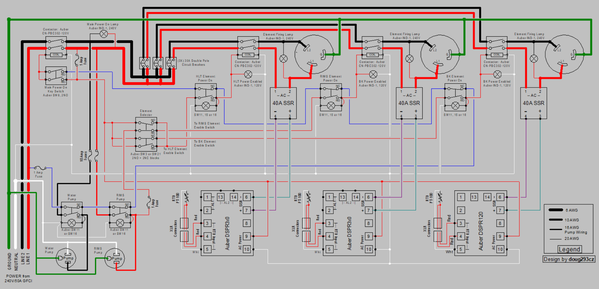
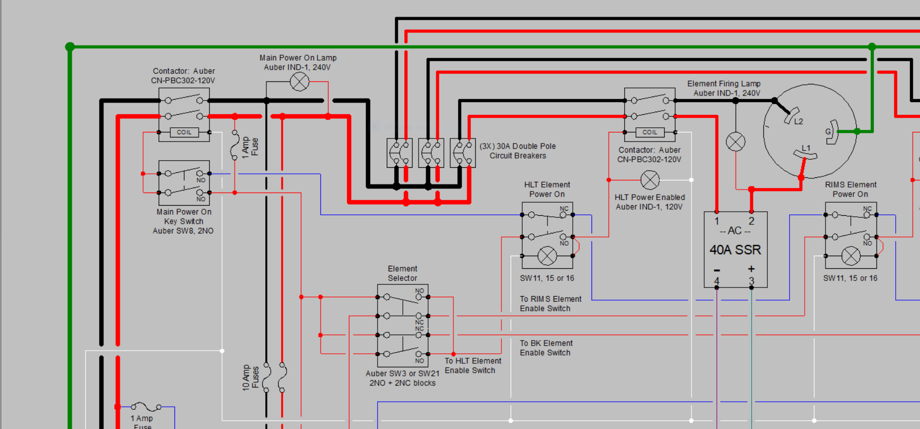
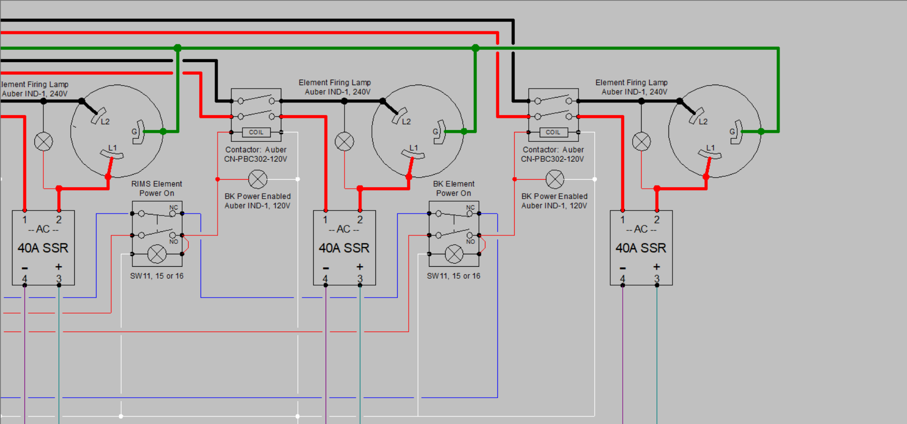
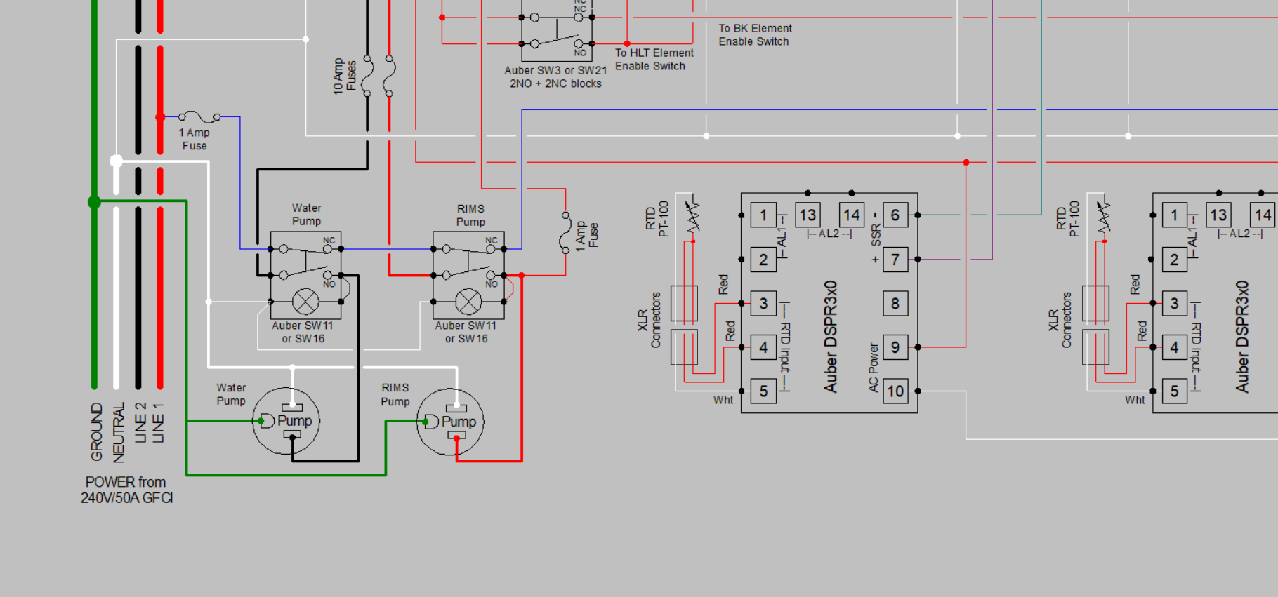
There are a lot of components in your design that are wired incorrectly. I have done a design that is very similar to what you are doing. The main difference is it's designed for a 50A GFCI feed, and three elements up to 5500W each. It features an "any 2 0f 3" switch that will only allow two elements to be enabled at a time, so that only 50A is needed. It also features a "safe start" interlock that prevents the main power from being turned on if any of the element, or pump switches is on. The schematic is below, and you can study it to see how the different component types are wired.


Edit: note that the main contactor (upper left corner) is spec'ed incorrectly. It needs to be an Auber CN-PBC402-120V, not a 302, or any other dual pole contactor rated for at least 250V and 50A resistive load.

Any 2 of 3 elements.PNG
Any 2 of 3 elements UL.PNG
Any 2 of 3 elements UR.PNG
Any 2 of 3 elements LL.PNG
Any 2 of 3 elements LR.PNG


If you have questions about the above design, just ask.

I'll start on my detailed critique of your schematic now.

Brew on :mug:
 
Last edited:
Ok, here's my critique of your original schematic:

Many of the components are wired incorrectly. I'll list those with mistakes below:
  • Contactors: These components have only 6 connections: two power in terminals for hot1 and hot2, two power out terminals for the switched hot1 and hot2, and two actuating coil terminals. For a 120V coil, one terminal is connected to a switched hot, and the other is connected to neutral. For a 240V coil, one terminal is connected to a switched hot, and the other to the other hot (which may be switched or unswitched.) These components to not have to be grounded since they are inside a grounded metal or non-conductive enclosure. Grounding may occur via a DIN rail (if the contactor is designed for this) or open frame contactors may be grounded to the metal mounting plate via the mounting screws.
  • LED lights (or any other type of light): These are never wired in series with another load. 120V lights are connected between a hot and neutral, and 240V lights are connected between hot1 and hot2. The hot wires are usually switched.
  • Heating Elements: Heaters have two power connections and a ground connection. 240V heaters have connections to hot1, hot2, and ground, but no neutral connection. 120V heaters have connections to hot, neutral, and ground, but no connection to the second hot. Therefore they should be connected with three bladed, rather than four bladed, plugs (NEMA L6-30 rather than NEMA L14-30.)
Now on to comments about your design:

You don't need the 63A circuit breaker in your panel, since you already have a 60A GFCI breaker in your SPA panel. Your main power feed should use 4AWG or 6AWG wire, depending on the temperature rating of the wire. Romex type wire (typically used for residential wiring) is only rated to 60°C, so 4AWG is required. Cable types starting with "TH"... are rated to 75°C or 90°C, so 6AWG could be used.

Once inside your panel, you're going to want to use smaller wires because they are cheaper, and much easier to work with. Then, wherever you reduce the wire size, you will need a breaker or fuse appropriate for the specific wire size. 30A-32A breakers for 10AWG wire, 20A breakers for 12AWG wire, 15A breakers for 14AWG wire, and 10A breakers for 16AWG wire.

4500W heating elements will draw 18.75A, so will need either 12AWG wire and 20A breakers, or 10AWG wire and 30A (or 32A) breakers. A 2500W (@240V) element will draw 10.4A, so could be wired with 14AWG and 15A breaker, or 12AWG/20A, or 10AWG/30-32A.

Typical 120V brewing pumps (RipTide, Chugger, March) draw less than 1.5A, so you can run two pump circuits from a single 10A breaker/fuse with 16AWG (or larger) wire.

PIDs, contactor coils, and LED indicator lights all take just a few milliamps each, so you can usually run all those circuits off a single 1 - 5A fuse, using 18AWG or 16AWG wire.

Don't bother with separate power switches and indicator lights for the PIDs. The PIDs should be connected to the main (switched) power bus in the panel thru an appropriate fuse. They will all power on when the main power is turned on, and the front panel lights on the PIDs will tell you they are powered up.

You need switches for each of the element power contactors. You should probably use lighted switches, or discrete indicator lamps, that light up when the switch and contactor are on.

Since this is a RIMS system, the power input to the RIMS contactor control switch should come from the RIMS pump switch. This prevents the RIMS element from being powered unless the RIMS pump is on. I consider this an absolutely necessary interlock to prevent a common operator error.

I highly recommend adding element firing indicator lights, that tell you when power is actually being applied to the elements. The firing LEDs on the front of the PIDs only tells you that the PIDs think they are telling the SSR to turn on, not that they are actually working. The discrete element firing lights tell you that things are actually working. They will also tell you if an SSR gets stuck in the "on" state (the most common SSR failure mode.)

DSPR110s are obsolete, and have been replaced by the DSPR120. If you already have the 110s they are still fine to use, but the terminal assignments are different than for the current model DSPRs.

If you use a metal enclosure, the enclosure must be grounded. Many enclosures come with a welded, threaded stud for this purpose. If you don't have pre-existing grounding studs, you can use machine screws thru holes in the enclosure. Paint should be removed from where the screw head and nut make contact, and star washers should be used as well. Both the main body and door need to be grounded.

Most of the components inside the enclosure do not need to be individually grounded. Exceptions are any component that has a dedicated ground connection, and the metal base plates of the SSRs (since the heatsinks for them will be exposed outside the enclosure.)

That's all I can think of right now.

Brew on :mug:
Thank you so much for taking the time to write this up. I apparently need to go back to the drawing board on this project. Thanks for attaching the schematics for your brew panel, those will certainly be helpful in reworking this project.
 

Latest posts

Back
Top