Am I stoopid?

Homebrew Talk - Beer, Wine, Mead, & Cider Brewing Discussion Forum

Help Support Homebrew Talk - Beer, Wine, Mead, & Cider Brewing Discussion Forum:

This site may earn a commission from merchant affiliate links, including eBay, Amazon, and others.

ChrisfromAbby

Well-Known Member
Joined
Jan 21, 2013
Messages
225
Reaction score
39
Location
Abbotsford
I'm considering apostasy....
I've been brewing with propane for probably 15 years, but am considering a switch to electric. At least the propane guys probably don't even read this thread, I should be safe.
I've been using little STC-100s forever, got 4 or 5 of them around for controlling my keezer and fermentation fridge and a sous vide thing.
I've built a control panel for my propane based brew bench using such as well.
But I want to stick my toe in the electrified waters.
I was trying to build a heat stick. My efforts have been exasperatingly sucky. Frickin thing leaks no matter what. I give up. It's not worth the aggravation.
So then I contemplated a built in element, but hey, why not go to 5500 watts? Then a timer for the 4hour ramp up time wouldn't be needed.
Cool. I've already got a noice long 240v extension cord that plugs into my dryer receptacle for my welder.
So I just need a temperature controller for 240v to regulate the HLT.

So I found this INKBIRD IPB-26 30A/240V Pre-Wired Digital Home Brewing Heating&Water Pump PID Temperature Controller

Which looks just about perfect, except for the $600 price tag!

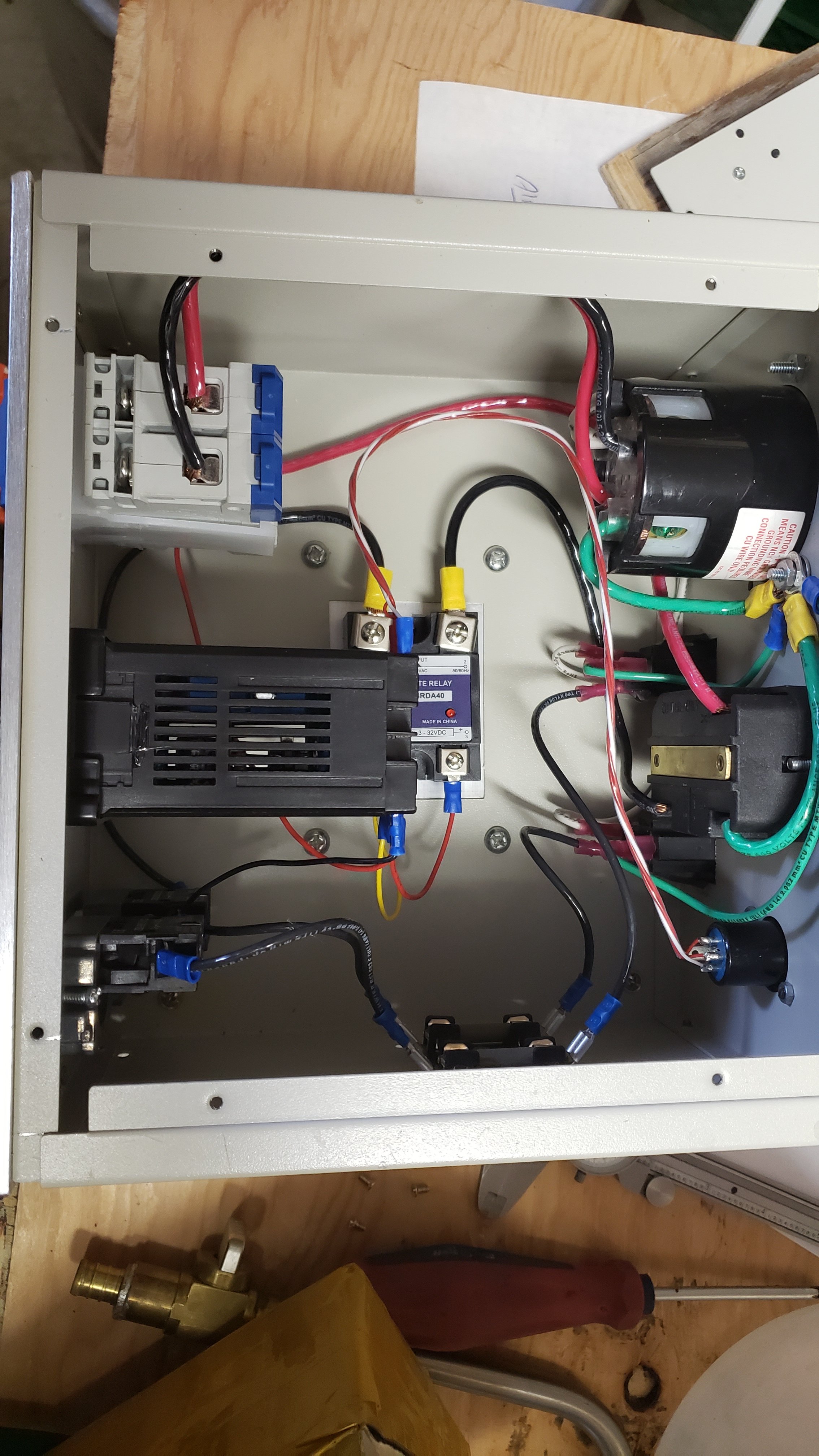
Having built my own TCs using an STC before, how much harder can it be to build a PID controlled one with 240v?
Inkbird sells this kit Inkbird Digital PID Temperature Controller on/off Thermostat ITC-100VH + K sensor+ SSR
that appears to have almost everything but the box to put it in, the cable and connectors.
I guess mine wouldn't have a slick, built-in pump controller but I don't know if I need that. I usually just let the pump recirculate constantly while I'm heating the water anyhow.

Anyone with experience building such want to chime in? Construction pointers, connector issues, safety?

Chris
 
I don't have any experience building my own electric brewery...but I did make the switch from propane when I bought my Brewzilla 65L. Let me tell you best decision I've ever made.

Heat times are faster, more precise temp control on the mash...can't speak more highly of it!
 
That price point looks high for what is included. It also doesn't appear to have any means of galvanticly isolating the input power from the element output. An SSR is a current switch, and the element still has voltage on it when the SSR is off. Also, the most common failure modes for an SSR is in the "on" state. For these two reasons, having an electromechanical disconnect (contactor) is something I recommend.

Here's a design I have put together that matches (actually exceeds) the function of the InkBird IPC-26, that can be put together for less than the cost of the IPC-26.

DSPR300 1-Pump 1-Element 240V rev-2.PNG


You could also look at the Blichmann BrewCommander, but it has the same lack of electromechanical disconnect as the InkBird. But then it is $375.

Brew on :mug:
 
Thanks! I like how you've isolated the element. I would have thought that the SSR would control both Line 1 and Line 2, but obviously I see now that it would not.
It seems if you're running the the power to your Main Power Switch & Contactor through first the pump switch and then the Element power switch, thus when you turn on either the main power and contactor will loose power? Or is that second 1A fuse and line back to the 2nd pole of the main power switch a self sustaining loop?
Why not run the power to the main switch directly off line 1 (via the first 1A fuse), then power your pump, element contactor and PID from there (off the main power contactor)? Am I misreading the switches? Are those double break switches? Maybe this is to ensure that the pump and element are switched off at start up? It's been a while since Uni level physics....
Don't worry, I'll run it all by my electrician buddy before touching anything!
Chris
 
Last edited:
Thanks! I like how you've isolated the element. I would have thought that the SSR would control both Line 1 and Line 2, but obviously I see now that it would not.
It seems if you're running the the power to your Main Power Switch & Contactor through first the pump switch and then the Element power switch, thus when you turn on either the main power and contactor will loose power? Or is that second 1A fuse and line back to the 2nd pole of the main power switch a self sustaining loop?
Why not run the power to the main switch directly off line 1 (via the first 1A fuse), then power your pump, element contactor and PID from there (off the main power contactor)? Am I misreading the switches?
Chris
The blue wire makes up a "Safe Start" circuit. The main power cannot be turned on unless both the pump and element enable switches are "off." This prevents the pump or element from unexpectedly coming on when the main power is turned on. The path thru the 1 A fuse creates a self latching circuit once main power is turned on - you can turn on the pump or element switch without cutting power to the main power contactor. Turning off the main power switch breaks the self latching action, and re-enables the safe start circuit.

Current flows in a loop. If you interrupt the loop anywhere then current stops flowing. With no current flowing thru the element loop, there is zero power being generated in the element. Interrupting the loop in one place does not remove voltage from everywhere. That's why both hots go thru the contactors. The contactors block both voltage and current. There is some power lost in the SSR when it is on (~30W.) If you put an SSR on each hot leg, you would double that power loss. Not a big deal at the element, but now your heat sink has to take care of twice as much heat.

Brew on :mug:
 
What type of fuses would you suggest using?

Is it possible to move the probe of the RTD sensors from one thermowell to another? I'd like to be able to bring my HLT to mash-in temp, then switch the probe over to the MLT thermowell to control mash temp through my HERMS.

Chris
 
What type of fuses would you suggest using?

Is it possible to move the probe of the RTD sensors from one thermowell to another? I'd like to be able to bring my HLT to mash-in temp, then switch the probe over to the MLT thermowell to control mash temp through my HERMS.

Chris
Panel mount Buss type fuses are probably the most convenient. For 10A and higher, you might want to look at circuit breakers instead of fuses.

Moving the probe from the HLT to the MLT could cause the HLT and the MLT temp to oscillate. This is caused by the delay between HLT temp changes and the response in the MLT. You are better off having a separate thermometer for the MLT, and determining what the temp offset is between the HLT and MLT.

Brew on :mug:
 
Hmmm, I thought the whole point of a PID was that it would compensate for the lag and avoid overshoot? That is, it mimics what I already do manually (but better) by goosing the HLT burner as needed to control the mash temp.
To be clear, I'd only be switching the probe over once - i.e. once the HLT hits target infusion temp. From that point I'd only care what the MLT temp was. The HLT could be whatever it needed from then on and I wouldn't need to monitor it.
Are you saying that the disruption of moving from one vessel to another will cause ongoing swings?

Chris
Actually, PID's don't deal at all well with response lag. In a system with lots of lag between input and response, you have to reduce the max power input by a lot to prevent oscillation in the process temp. With the method you propose, the HLT will over heat before the mash temp responds. When the mash temp does heat enough for the PID to decide to reduce the power input, the mash will continue heating because the HLT will cool off very slowly.

Early in my career, we had a process that was done on hot plates. We originally used hot plates with manual power adjusting knobs, but these were not good at holding stable and precise temps. We got some new hot plates that had ~1" thick aluminum slab heat spreader tops, and PID's to control them. The temp probes were located in the center (vertically and horizontally) in the Al slabs. As I recall, the power for each plate was about 2000W. No matter how we adjusted the PID's we couldn't keep the temp from oscillating slowly (period was something like 45 minutes.) What I did that finally stopped the oscillation, and got us temp stability, was rewire the two heating elements in each unit from parallel to series. This cut the max power by a factor of 4, so max power was now ~500W. This resulted in slow initial heat up, but since these were pretty much on all the time, we didn't care about that. So, problem solved.

I doubt you want to increase your HLT heat up time by 4X. That's why you need to put your temp probe where it responds quickly to changes in HLT temp, and learn the characteristic HLT-MLT temp offset for your system. Then you just set the HLT temp higher by the difference.

Brew on :mug:
 
Sure, understood. What I've done in the past, is to place my MLT probe in the inflow to the MLT from the HERMS coil, rather than in the middle of the MLT. This allows for fairly rapid response to temperature increase and usually keeps my temps pretty stable. And that was with propane which is really prone to lags and overshoot due to the heat capacity of the outward in heat supply.
 
True enough.
Bad thread title.
Maybe better would be Am I Lazy? in that I was feeling like avoiding the work of building another panel to control a brewery component and was thinking of just buying my way in this time.
Doug293cz made it apparent that the new build is probably the smart move.
 
Parting it out though, still not cheap. Running $300 already before wiring, connectors and busses. I hope to salvage some parts from my propane controller box, but most of it was running on 120v AC and 24VDC and may not be compatible.
 
Current flows in a loop. If you interrupt the loop anywhere then current stops flowing. With no current flowing thru the element loop, there is zero power being generated in the element. Interrupting the loop in one place does not remove voltage from everywhere. That's why both hots go thru the contactors. The contactors block both voltage and current.

In another thread I discussed my eventual purchase of an Auber Cube and that I am generally very pleased with it. But this little issue is still in my mind for 2 or 3 reasons.
1 - safety. Nice to be able to KNOW there is no voltage at the element when it is supposedly "off".
2 - the whole SSR failing in the "ON" position issue
3- (a big one for me) be able to really turn the element OFF when I need to swap the power cord from the HLT to the BK.

More on #3
The Cube only has one element power supply, so I need to swap it over to the BK at the end of my mash. There is no way to do this simply. I've been adding a mash step of a lower temperature than my mash out to keep the circuit open for the minute it takes to do this, but I don't like it.
So, there is a small place where I could install a switch on the side wall of the Cube. The wiring looks like it will be pretty easy to do, but isn't this the sort of thing a contactor should probably be used for - 30A of 240v power? In fact, you put such in your wiring diagram. I just don't think there is enough physical room to place a contactor and a switch in the space available. Any suggestions? Maybe a small circuit breaker switch much like the main power switch would work?

Chris
 

Attachments

  • 20210329_155236.jpg
    20210329_155236.jpg
    1.1 MB · Views: 30
It might be possible to rewire the main power switch/breaker such that it only controls power to the element. The EZ-Boil would then come on as soon as the unit is plugged in, but the element couldn't turn on until the switch/breaker was turned on. The pump switch would also be "live" without the switch/breaker on. Is this of interest to you?

Brew on :mug:
 
Hmm. Maybe. I'm still not in love with the idea of connecting/disconnecting plugs with current actively flowing through them, although 120 is better than 240v.
 
Hmm. Maybe. I'm still not in love with the idea of connecting/disconnecting plugs with current actively flowing through them, although 120 is better than 240v.
The EZ-Boil draws less than 50mA. Unswitched phone chargers and computer power bricks draw much more than that, and they are routinely plugged and unplugged "hot."

It would be possible to add a low current switch that controls power to the EZ-Boil and the pump switch, but that gives you the possibility of enabling the element power before the EZ-Boil is powered up and initialized. I'm not a fan of that.

Brew on :mug:
 
The EZ-Boil draws less than 50mA. Unswitched phone chargers and computer power bricks draw much more than that, and they are routinely plugged and unplugged "hot."

Good point. The pumps a bit more than that though, if they were accidentally left "on".

It would be possible to add a low current switch that controls power to the EZ-Boil and the pump switch, but that gives you the possibility of enabling the element power before the EZ-Boil is powered up and initialized. I'm not a fan of that.

Not sure I follow you here, unless you're talking about ONLY putting in the low current switch to interrupt power to the EZBoil, This is actually what Auber has suggested to me. But wouldn't there only be power to the element when you powered up if the SSR had previously failed?

I'm thinking of combining the suggestions;
- using the circuit breaker switch to (only) interrupt power to the element by removing the 120v supply from there and moving it to the power supply receptacle. I believe this is what you had suggested?
- then placing a low current (120v) switch to control supply to EZBoil and the pumps.

Does this seem like a sound approach?

Chris
 
I believe the EZBoils power on in the same state they were in when powered down (haven't read the manual in a while.) So, if the EZBoil got shut down while in a temp or power control mode, it could power up the element as soon as the main power switch was turned on. Could be a serious issue if the element wasn't covered by liquid when the power is turned on.

Here's something that should give you a good idea of a mod that should do what you want. There is a power switch that controls both power to the PID and power to the pump switch. The circuit breaker switch then controls only power to the SSR & element.

Modified Auber Cube Wiring.png


Brew on :mug:
 
Cool. I don't believe there is a 1A fuse for the EZBoil in the stock Cube. Definitely there are fuses for each pump. I'll have to go look because it certainly is a good idea if not code. 🤔
Does it matter of the breaker switch is before or after the SSR do you think? Before is certainly a cleaner design and actually probably easier to wire.
Chris
 
I leave my controller plugged in 24/7 with the EZboil on but the element enable contactor off. If you REALLY felt the need to have a low current switch before the EZboil power contacts to make it dark, there's nothing wrong with that. The pump already has an on/off switch so another upstream switch that basically enables/disables the ability to turn the pump on and off is redundant.
 
Cool. I don't believe there is a 1A fuse for the EZBoil in the stock Cube. Definitely there are fuses for each pump. I'll have to go look because it certainly is a good idea if not code. 🤔
Does it matter of the breaker switch is before or after the SSR do you think? Before is certainly a cleaner design and actually probably easier to wire.
Chris
As a general design philosophy, I like to place switches as close to the incoming power as possible. This way more of the total circuitry is isolated from power when the switch is off. So I would place the breaker/switch between the incoming power and the SSR.

There are a lot of controllers around that place the element switch/contactor after the SSR, and they work. However, the switch/contactor cannot remove power from a failed SSR.

Brew on :mug:
 
The pump already has an on/off switch so another upstream switch that basically enables/disables the ability to turn the pump on and off is redundant.
I was just thinking this too.
When I looked more closely at the 120v wiring of the Cube, the pumps and the EZBoil run off the different hot phases. Probably to isolate 60 cycle interference from the motors affecting the electronics of the controller I'm guessing. So I actually DON'T want to have a common power switch to both pumps and EZBoil. Maybe I'll simply put in a single illuminated DC rocker switch to the control line for the SSR.

Thanks!
A switch in the control line to the SSR is useless in isolating an SSR that is stuck in the "on" state, so you have to shut the whole system off if your SSR latches. Not an unworkable arrangement, but you do have to remember that the SSR control switch won't do the job.

Brew on :mug:
 
I was just thinking this too.
When I looked more closely at the 120v wiring of the Cube, the pumps and the EZBoil run off the different hot phases. Probably to isolate 60 cycle interference from the motors affecting the electronics of the controller I'm guessing. So I actually DON'T want to have a common power switch to both pumps and EZBoil. Maybe I'll simply put in a single illuminated DC rocker switch to the control line for the SSR.

Thanks!

You're reading too far into it. The EZboil does not react in any way to being on the same leg as a pump motor. It probably wasn't wired that way for any reason. I would just move the power supply hots for the EZboil and pump switch to "pre-main switch" and call it a day. You get the positive 240 disconnect you want while allowing for EZboil programming and pump operation completely independent of whether the element is enabled or not.
 

Latest posts

Back
Top