
shoo
Well-Known Member
- Joined
- Aug 14, 2017
- Messages
- 93
- Reaction score
- 28
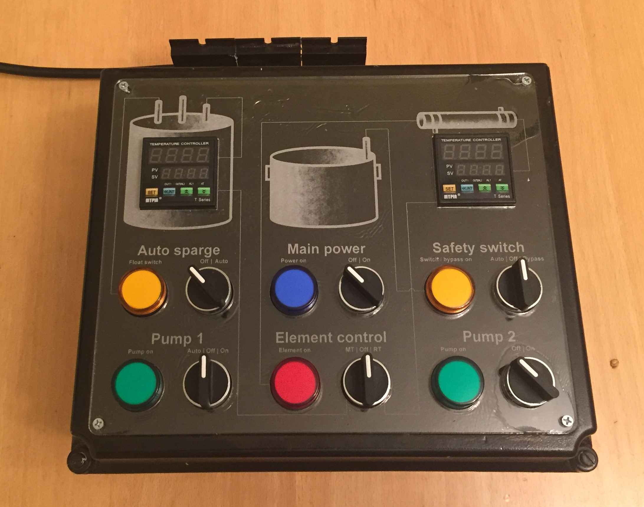
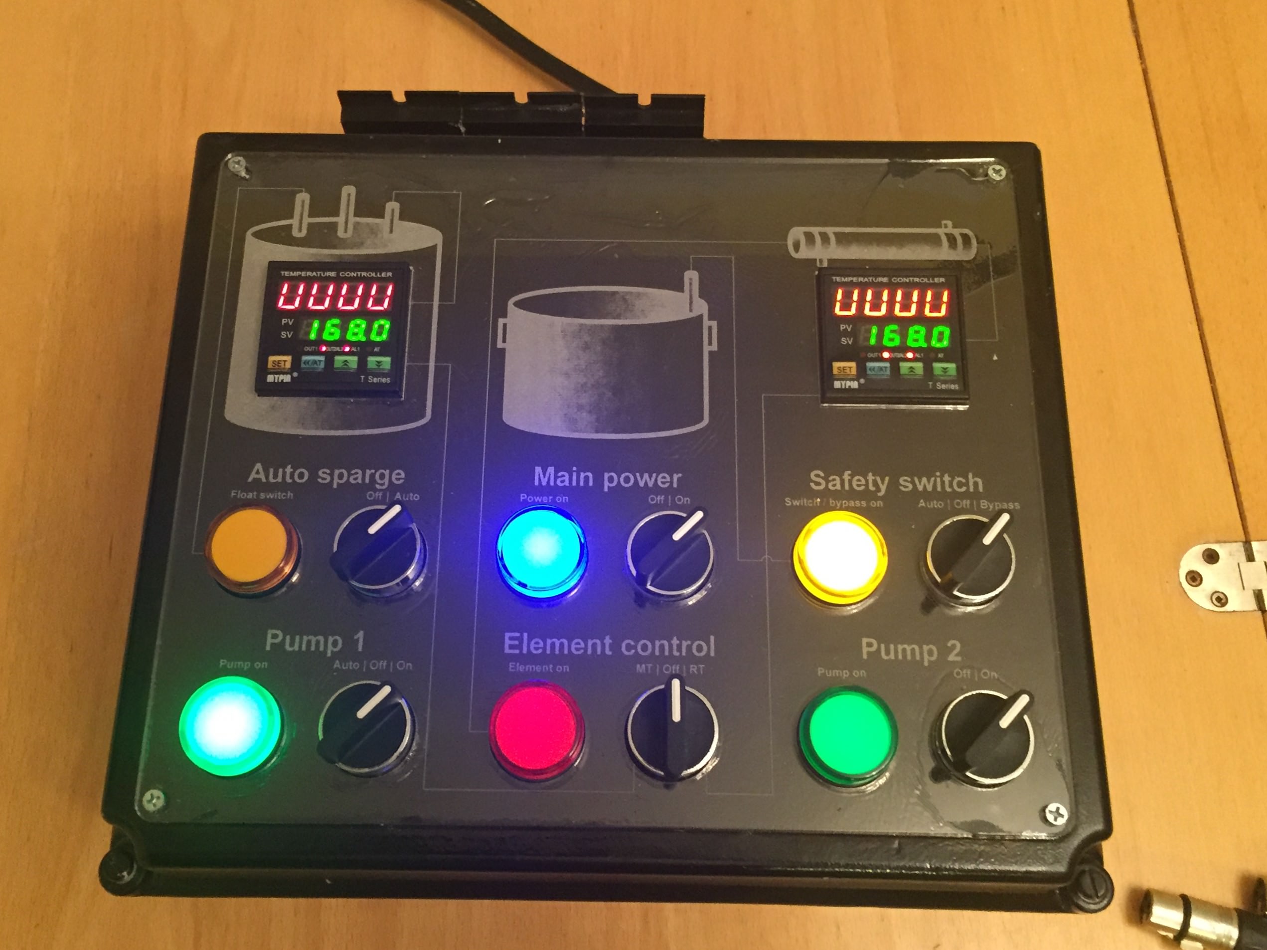
Built a control panel box for my hybrid RIMS/HERMS setup. Pretty happy with the way things turns out, and wanted to share a few things I learned along the way that I didn't see in other builds' DIY threads. This is a system which powers a single 1325W @120V RIMS tube, a chugger pump, and a 12v solar pump (system shown in this thread).
My panel is a bit different than others, in part because I built a few things in that aren't in the Kal build, most notably the electric auto-sparge and a safety switch for the heating element. Each of the float switch ports on the side panel goes to a float switch which either completes the circuit or doesn't (2 of the 3 XLR pins), which in turn triggers a relay. The MT one determines the level of water in the MT for sparging, where if the level is too low it triggers the chugger pump to pump more sparge water in. The RT one determines whethere there is water in my HLT above a set level. If not, it disables the element firing. I'll be switching that to a flow switch in the future.
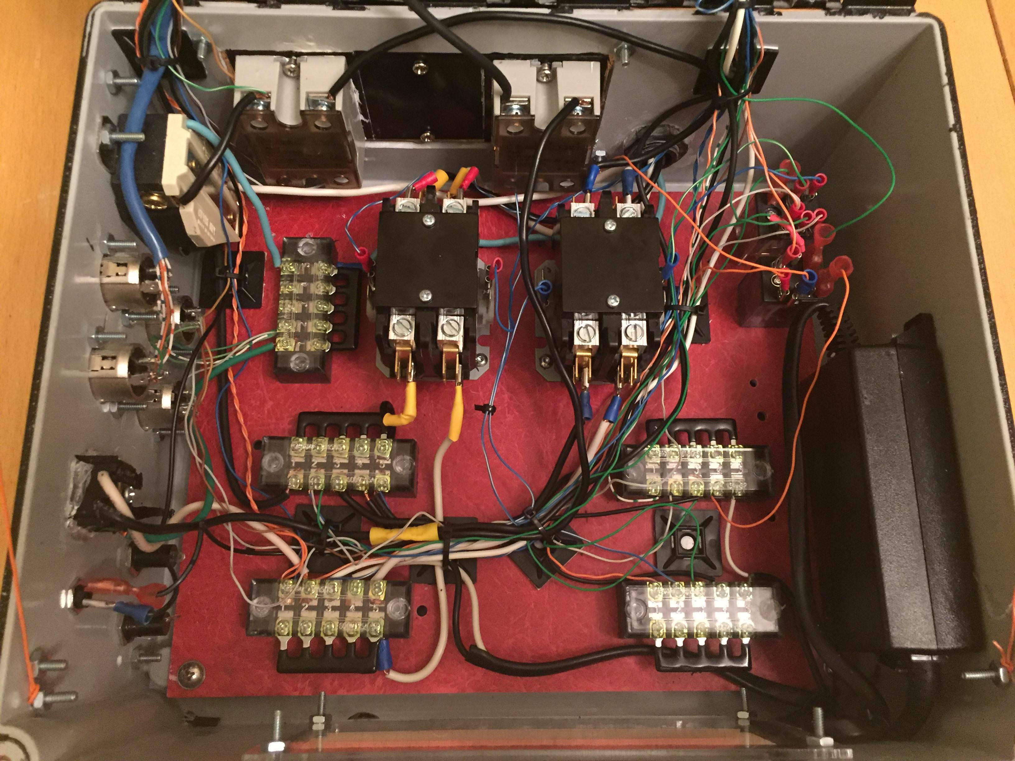
One other limitation is that I was trying to save money, so a lot of this is built with scrap parts (most notably almost all the wiring, the enclosure, and the DC transformer).
On the other hand, I had access to a laser cutter, which was amazing. In addition to getting to laser etch some nice labeling (pro tip: etch it in mirror, and mount it flipped it over so the etched side touches the enclosure), but it also helped with one other thing: I also cut / etched drill guides as part of the panel build. The circles cut out for the switches for example, also had smaller circles in their centers, which I used to precisely center the pilot holes when drilling into my enclosure. That made life easier for sure.
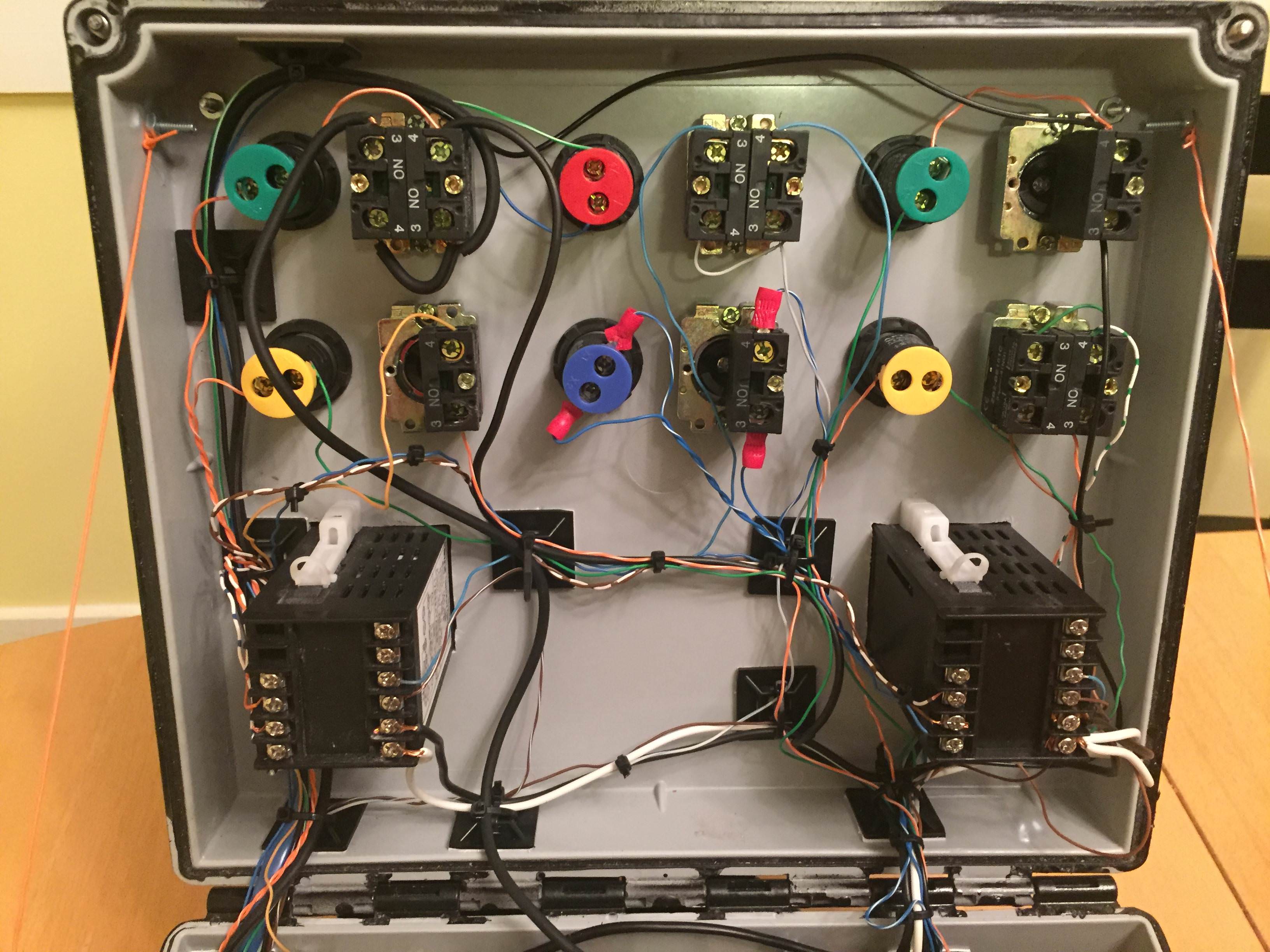
As mentioned, almost of the wiring is scrap. In particular, one thing worth noting is that all of the super thin wire for low-power stuff (signals, relay coils, lights, and DC power) is 24AWG harvested from dead ethernet cables. Ethernet/cat5 cables are made up of 4 pairs of twisted 22-24AWG (i.e. 8 wires). One scrap ethernet cable gives you a LOT of wire to work with.
Also note: I haven't bothered to actually wire in fan control (turns out not necessary, as I am not generating that much heat) or the fuses. May do that eventually. Probably not.
But without further ado:
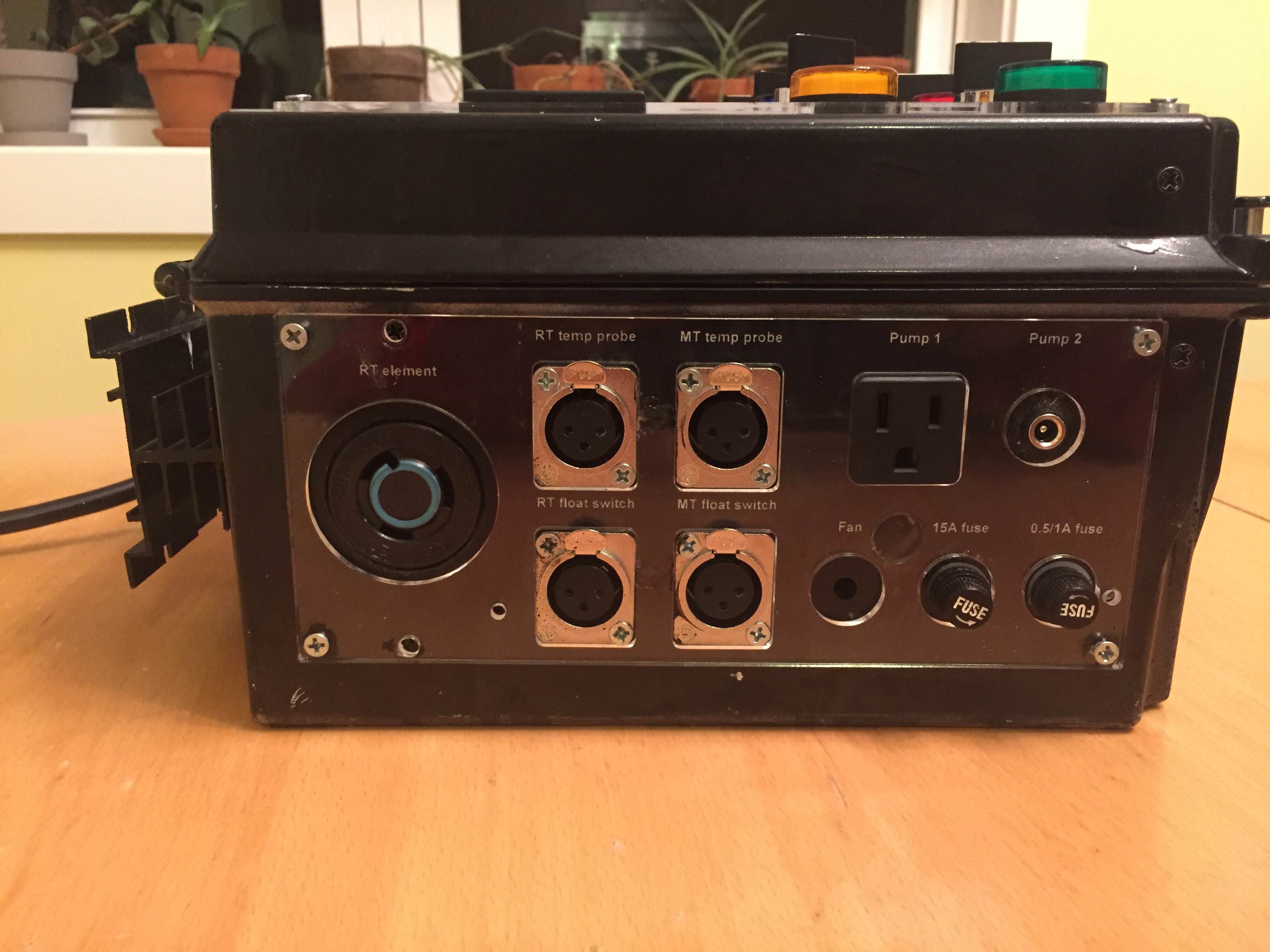
My panel is a bit different than others, in part because I built a few things in that aren't in the Kal build, most notably the electric auto-sparge and a safety switch for the heating element. Each of the float switch ports on the side panel goes to a float switch which either completes the circuit or doesn't (2 of the 3 XLR pins), which in turn triggers a relay. The MT one determines the level of water in the MT for sparging, where if the level is too low it triggers the chugger pump to pump more sparge water in. The RT one determines whethere there is water in my HLT above a set level. If not, it disables the element firing. I'll be switching that to a flow switch in the future.
One other limitation is that I was trying to save money, so a lot of this is built with scrap parts (most notably almost all the wiring, the enclosure, and the DC transformer).
On the other hand, I had access to a laser cutter, which was amazing. In addition to getting to laser etch some nice labeling (pro tip: etch it in mirror, and mount it flipped it over so the etched side touches the enclosure), but it also helped with one other thing: I also cut / etched drill guides as part of the panel build. The circles cut out for the switches for example, also had smaller circles in their centers, which I used to precisely center the pilot holes when drilling into my enclosure. That made life easier for sure.
As mentioned, almost of the wiring is scrap. In particular, one thing worth noting is that all of the super thin wire for low-power stuff (signals, relay coils, lights, and DC power) is 24AWG harvested from dead ethernet cables. Ethernet/cat5 cables are made up of 4 pairs of twisted 22-24AWG (i.e. 8 wires). One scrap ethernet cable gives you a LOT of wire to work with.
Also note: I haven't bothered to actually wire in fan control (turns out not necessary, as I am not generating that much heat) or the fuses. May do that eventually. Probably not.
But without further ado:
