A/C glycol chiller w/ two 14 gal SS Brewtech conicals

Homebrew Talk - Beer, Wine, Mead, & Cider Brewing Discussion Forum

Help Support Homebrew Talk - Beer, Wine, Mead, & Cider Brewing Discussion Forum:

This site may earn a commission from merchant affiliate links, including eBay, Amazon, and others.

Tiber_Brew

It's about the beer.
HBT Supporter
Joined
Apr 21, 2010
Messages
2,541
Reaction score
281
Location
Upper Peninsula
I've seen a few DIY glycol chillers made from window A/C units, so this isn't anything entirely new. Thought I'd share my build, and how I integrated it with my system with two new 14 gallon SS Brewtech conical fermentors. I finished this project last winter, and it has worked very well for me so far.
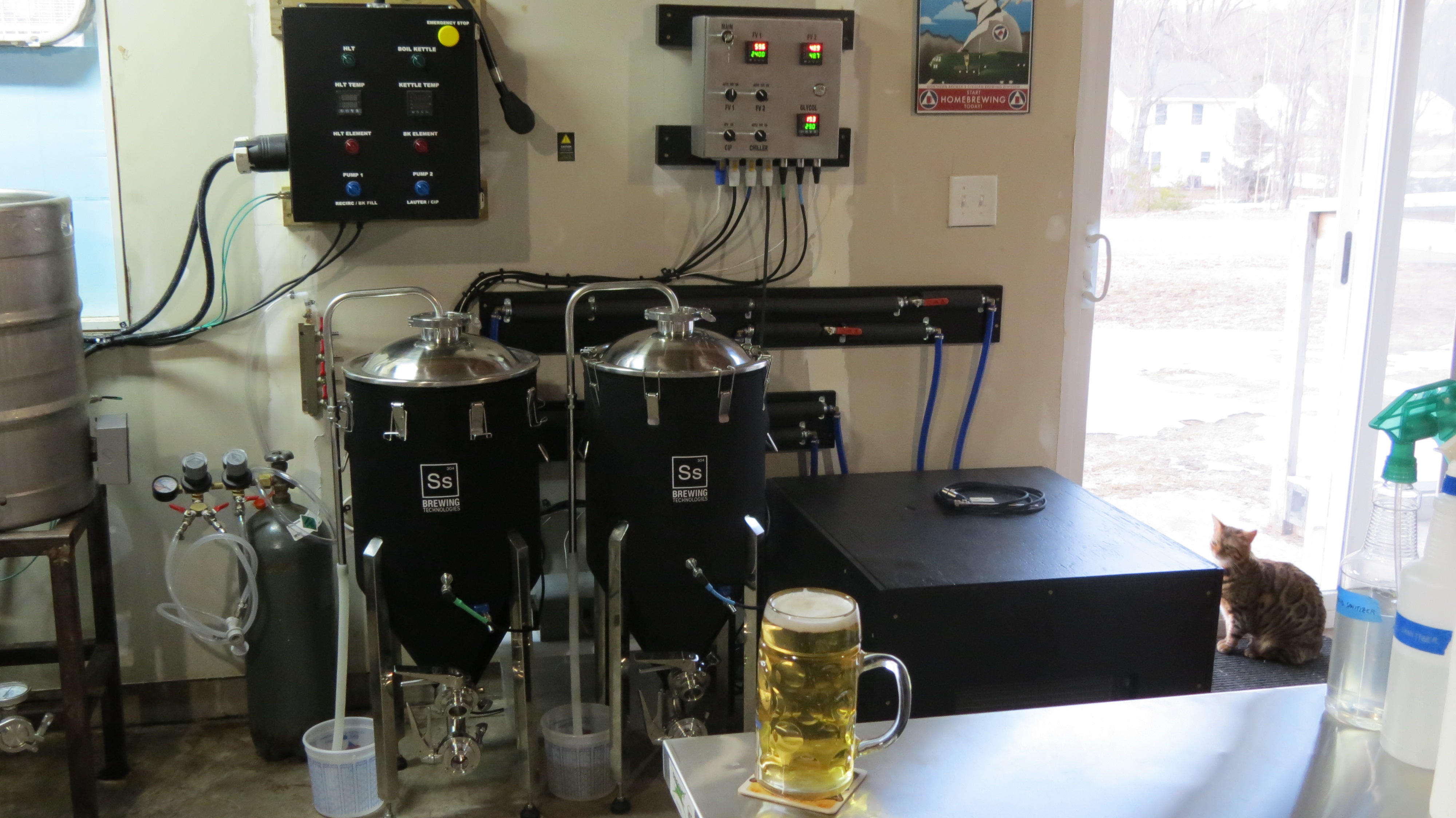
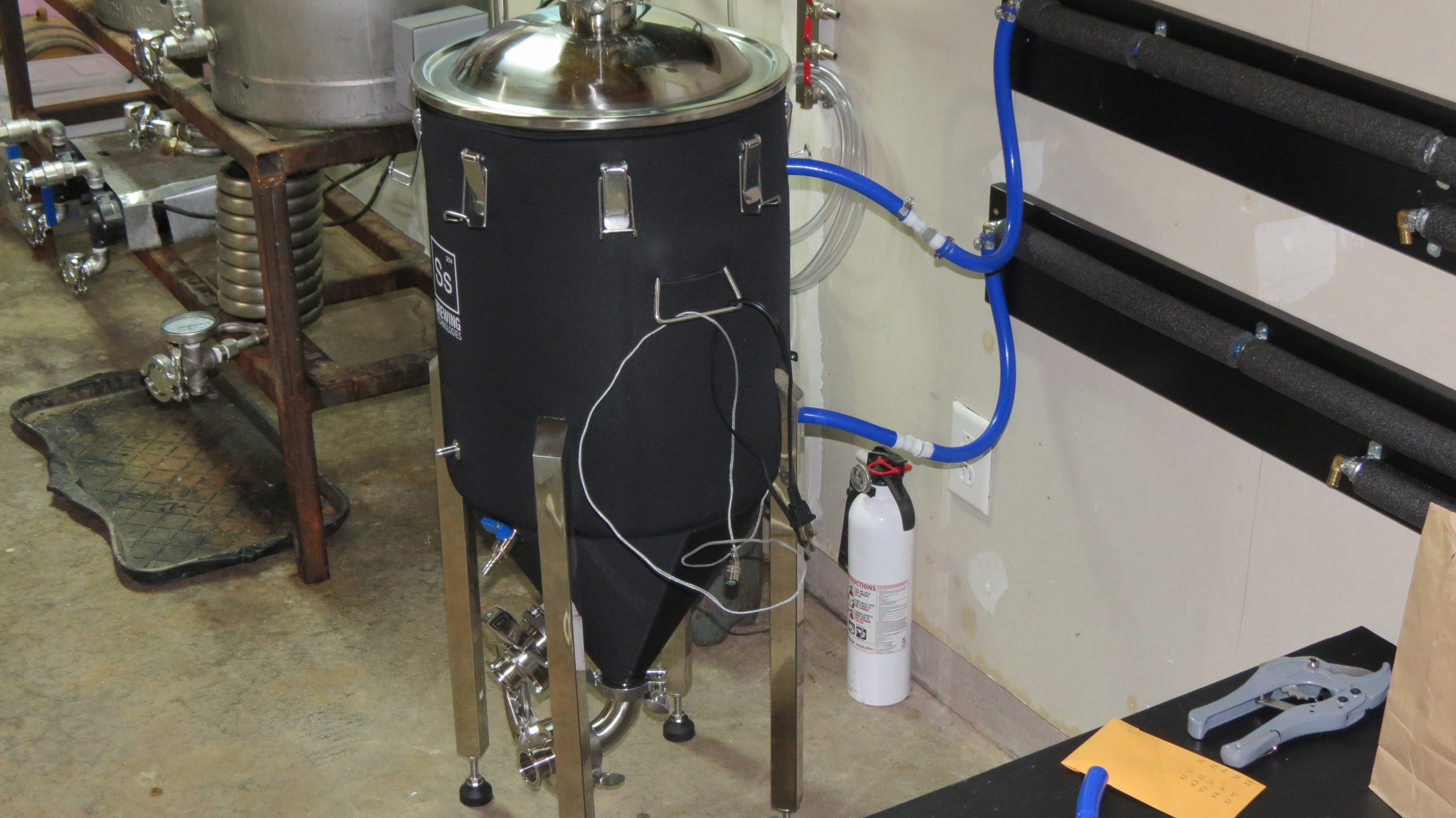
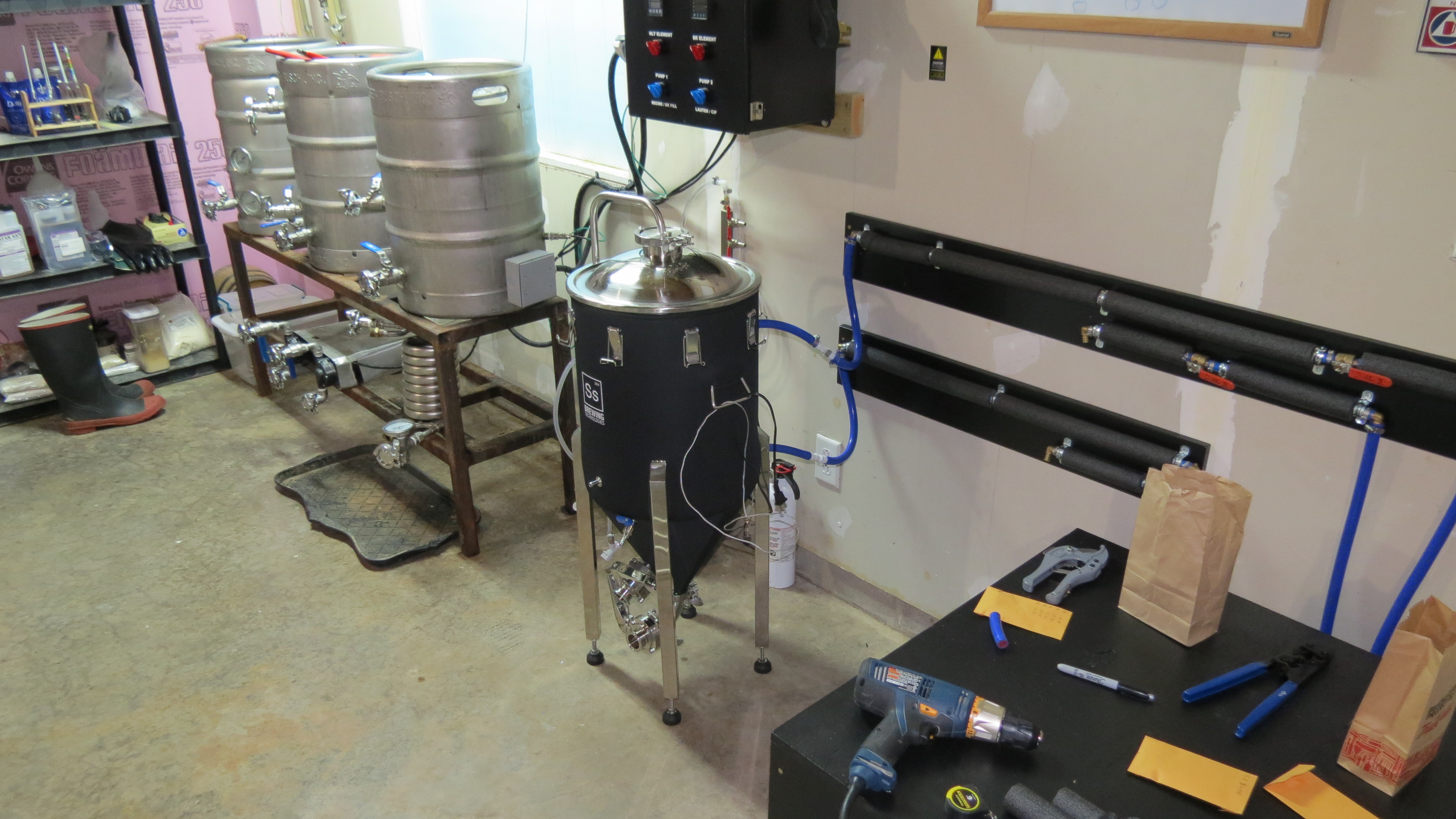
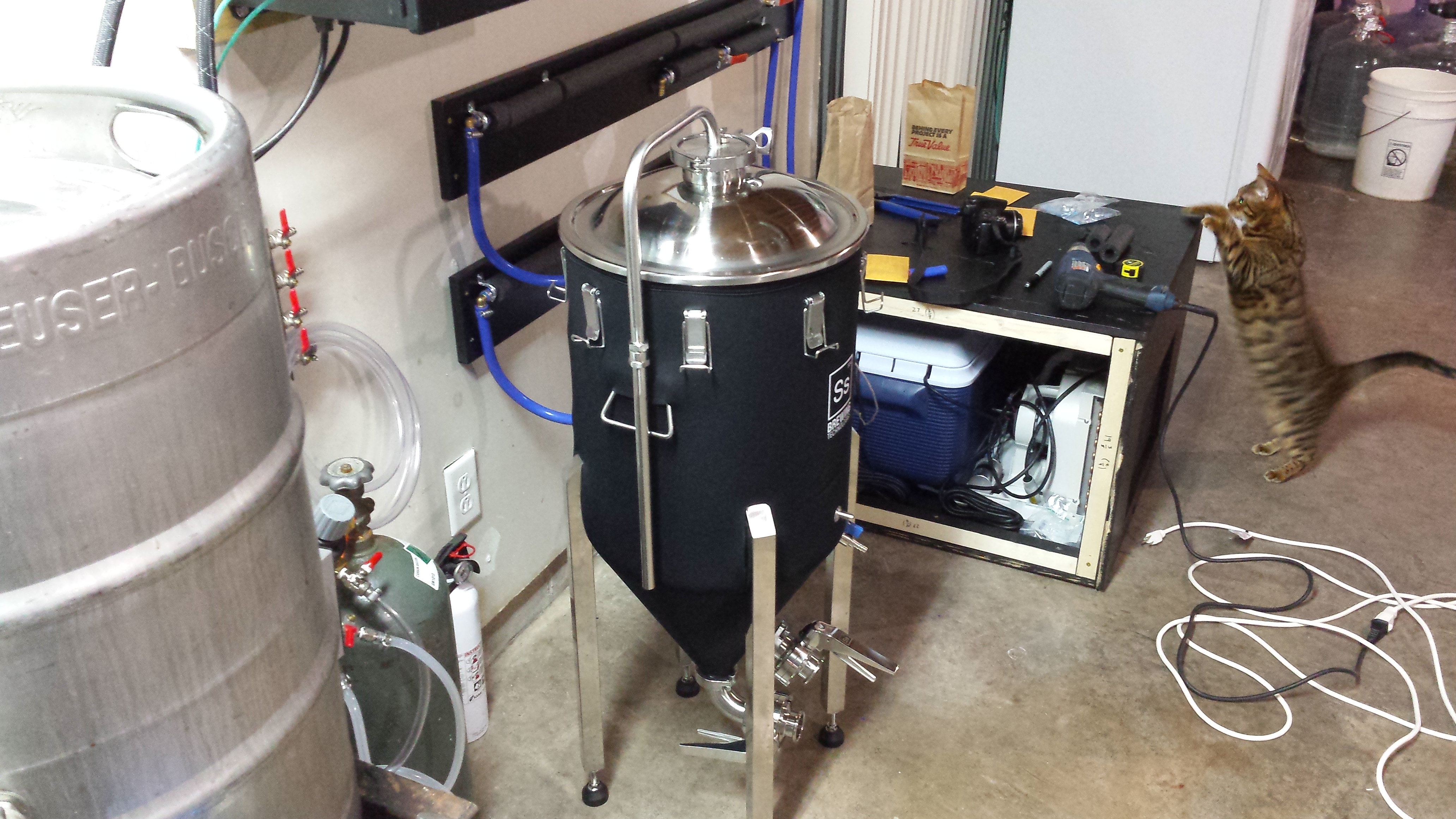
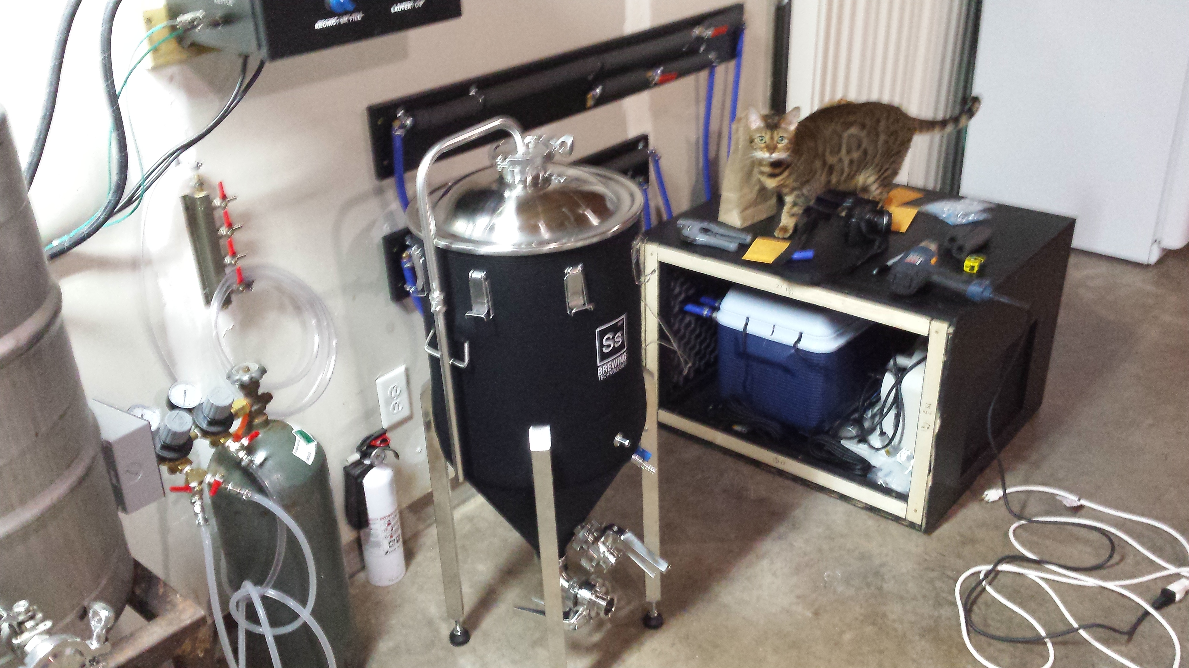
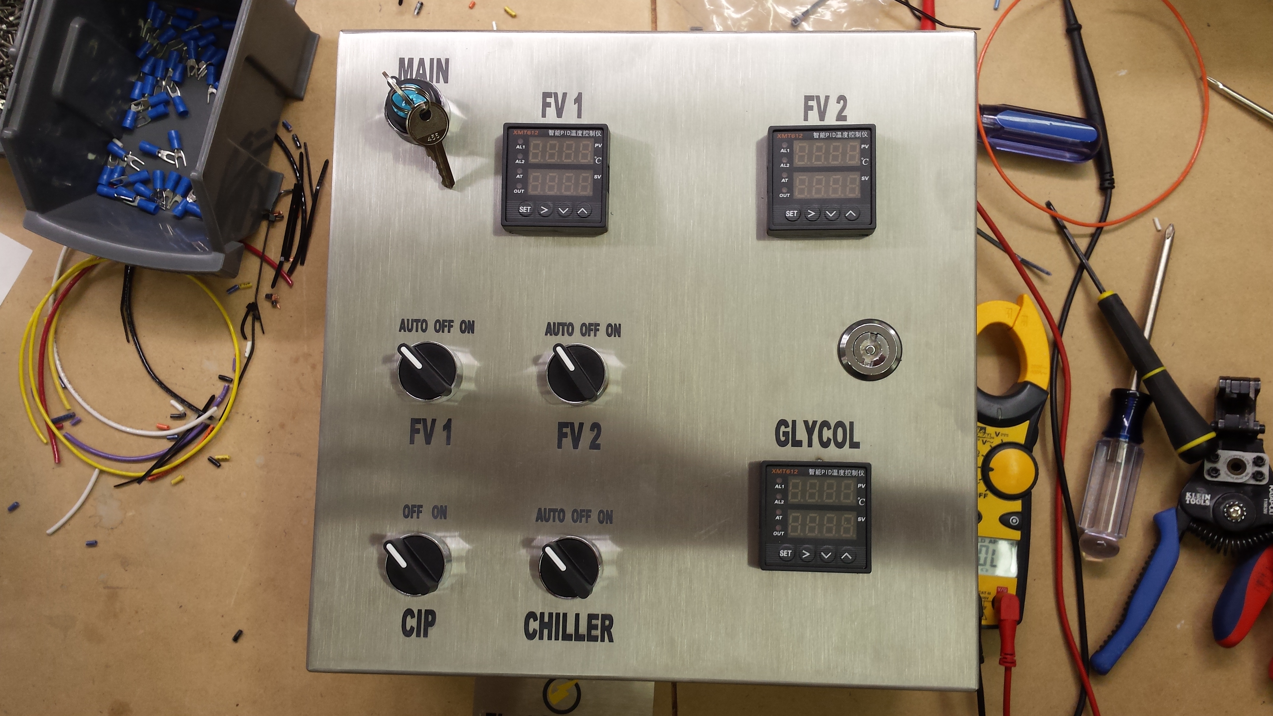
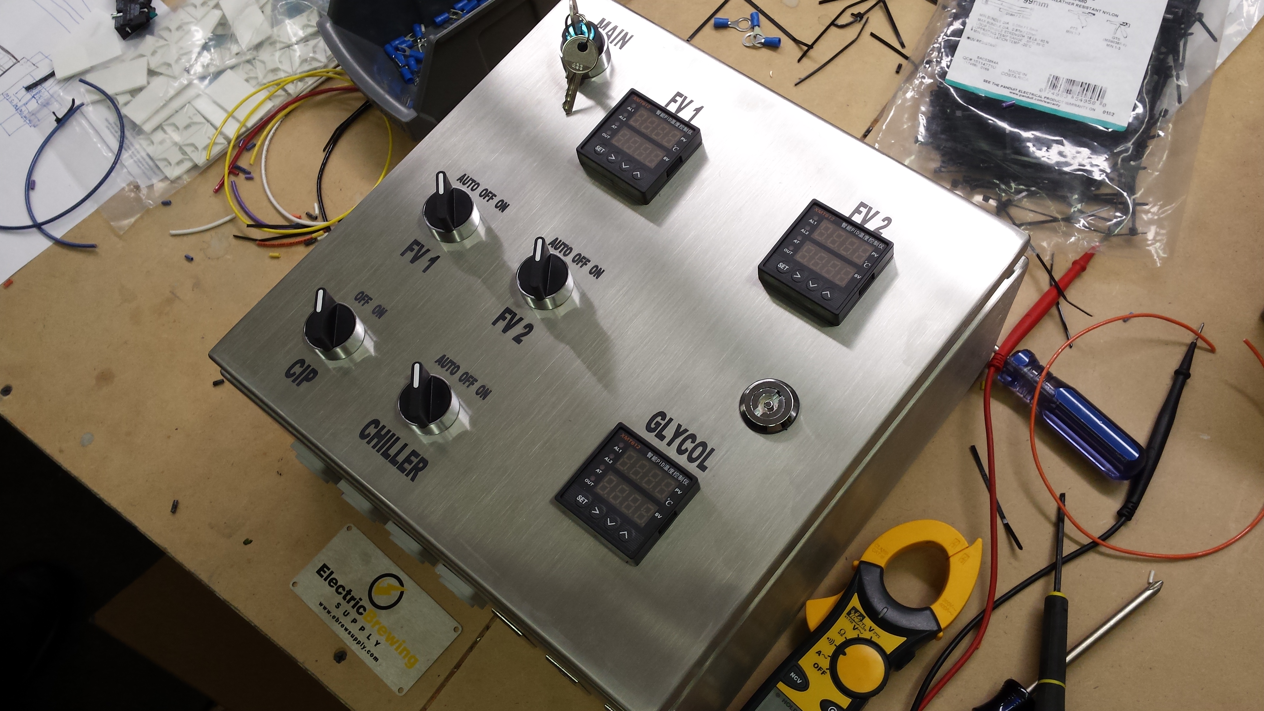
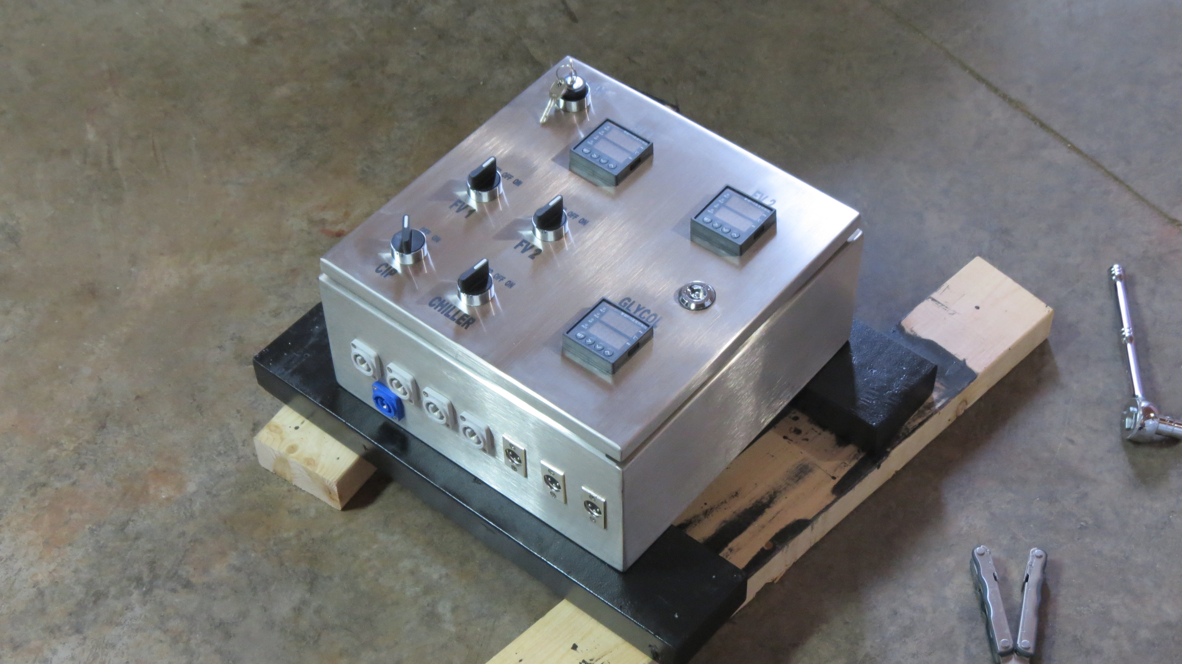
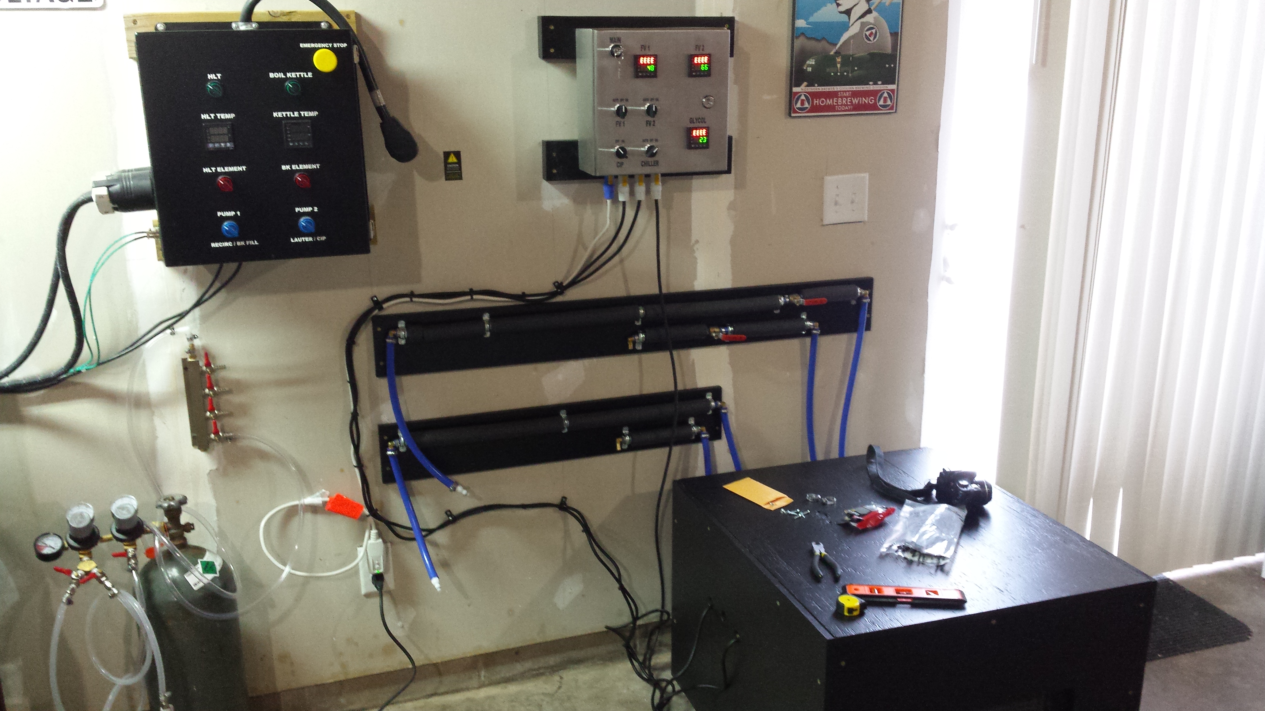
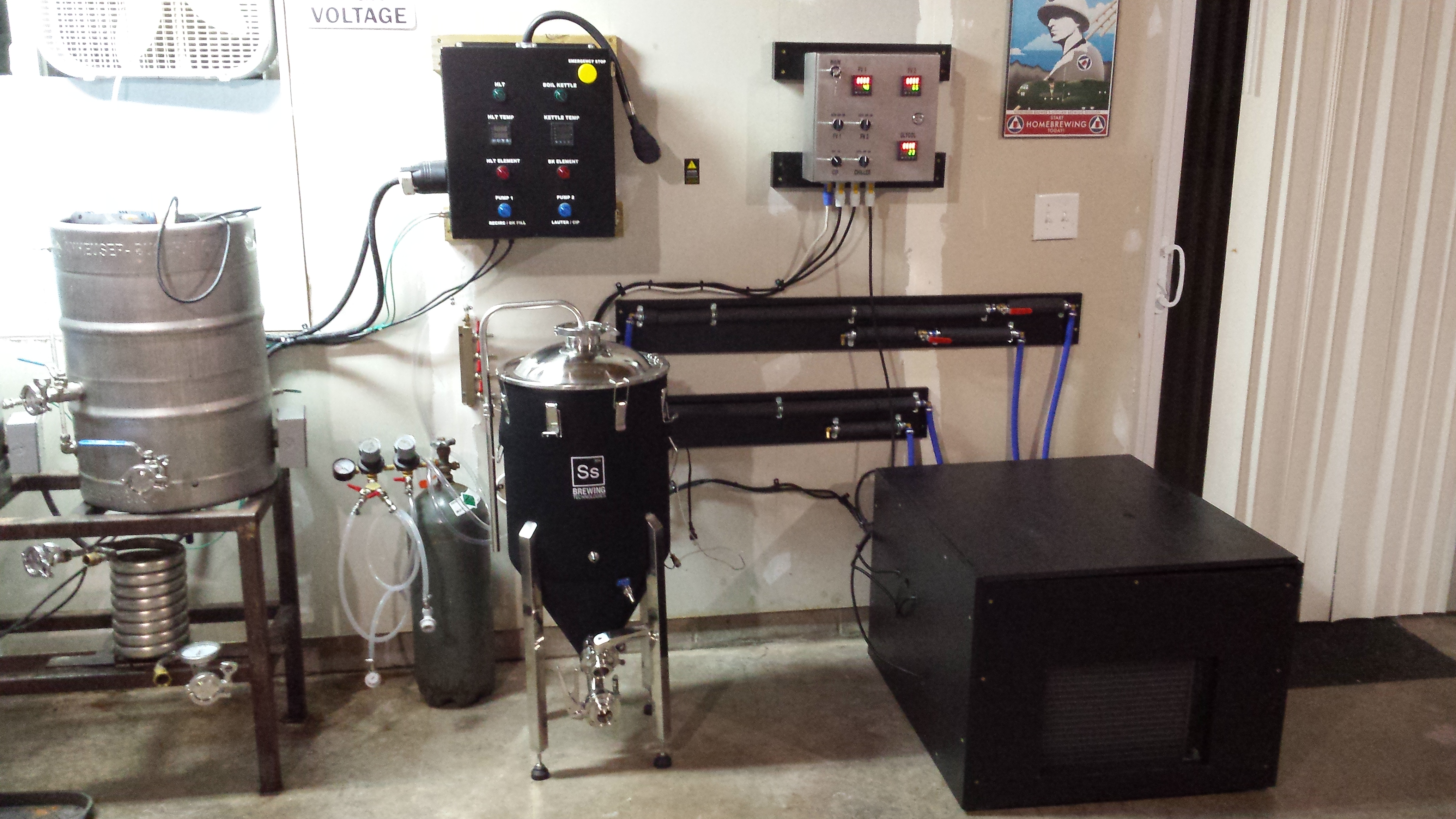
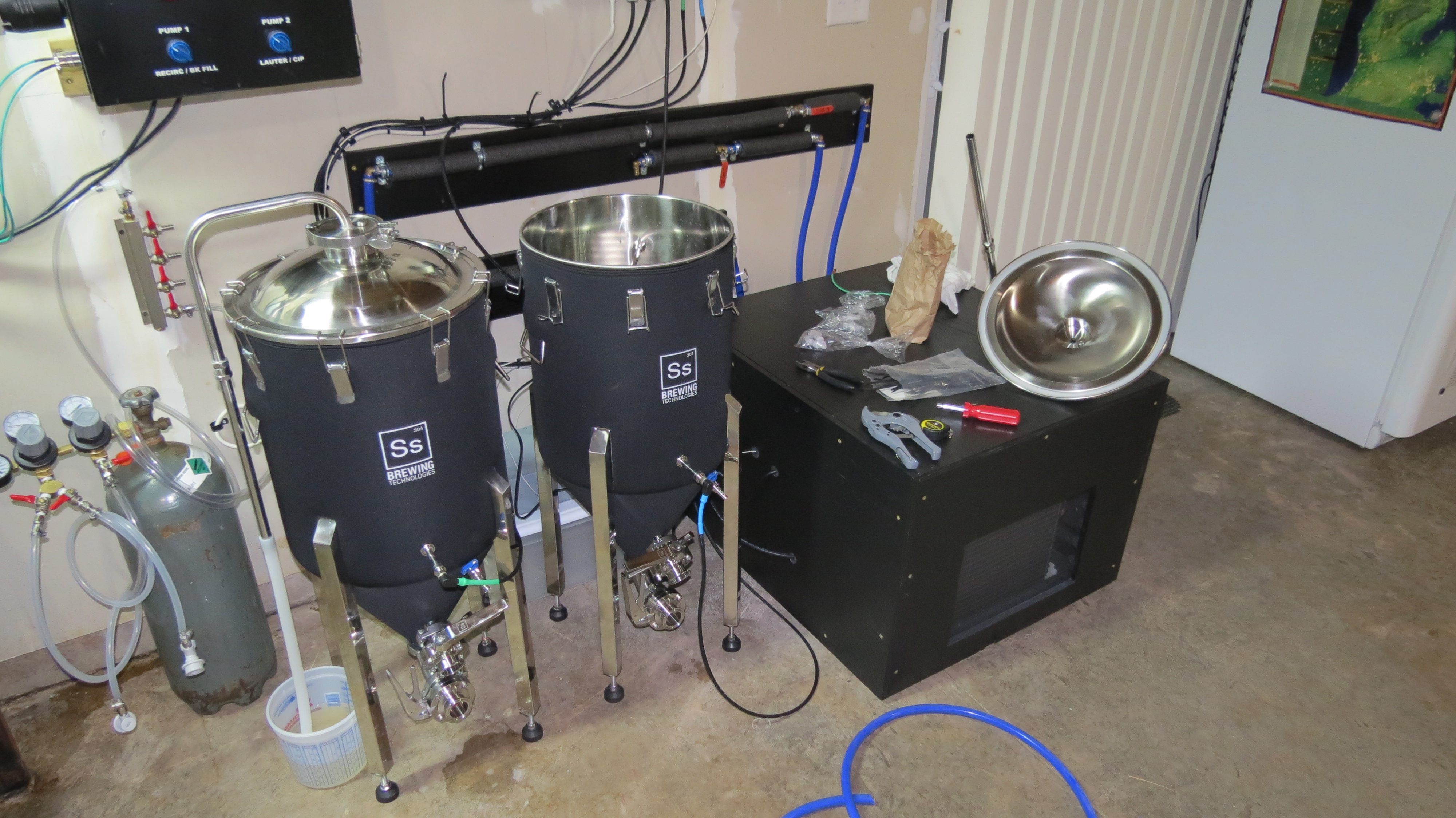
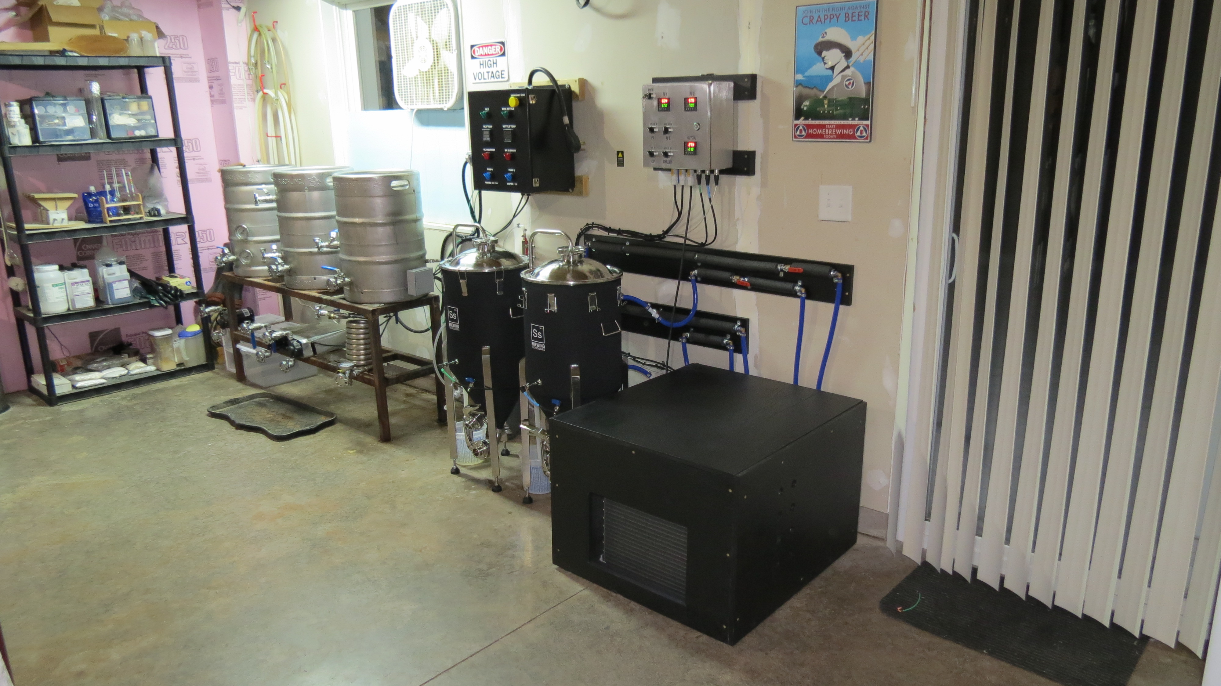
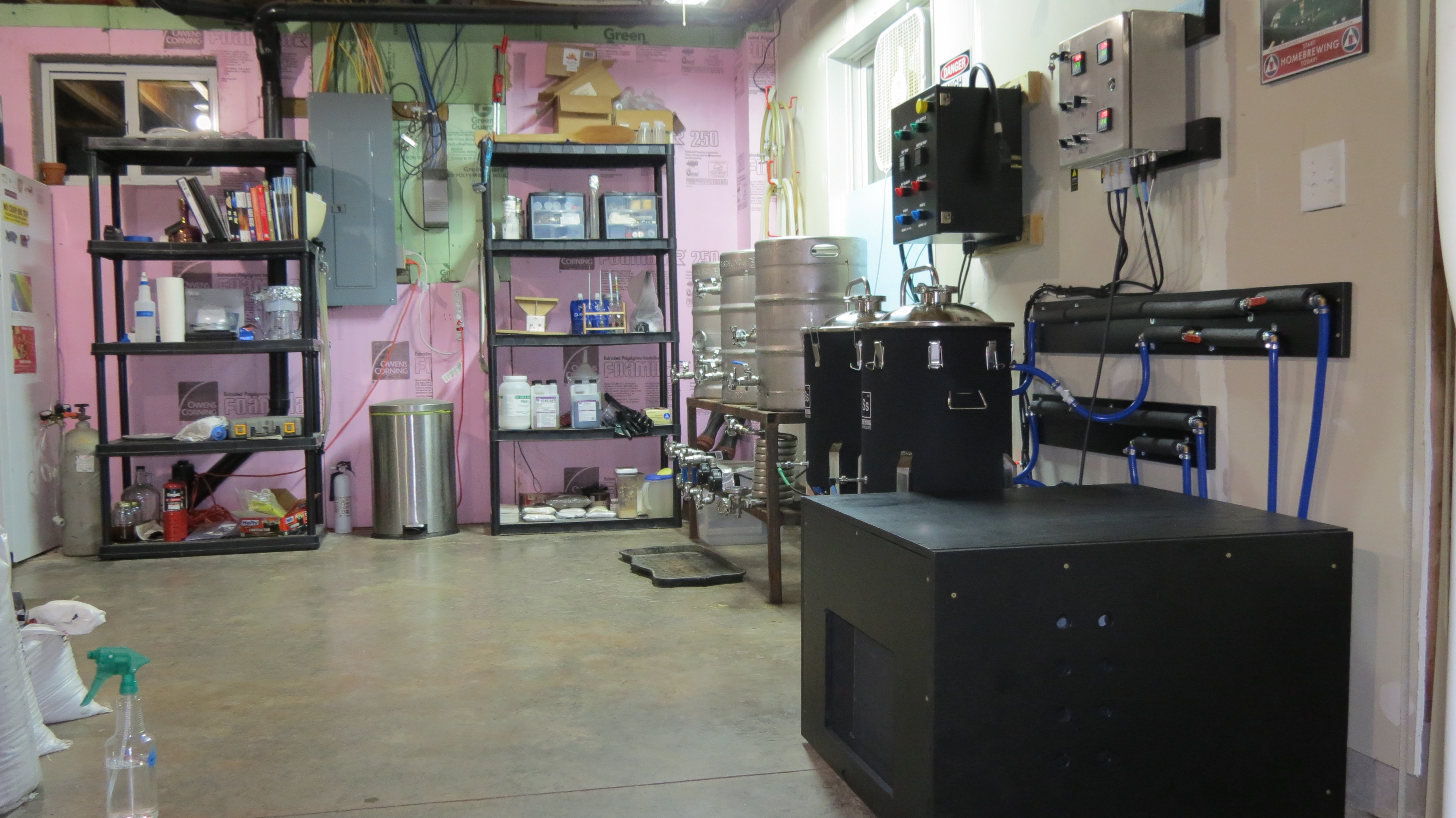
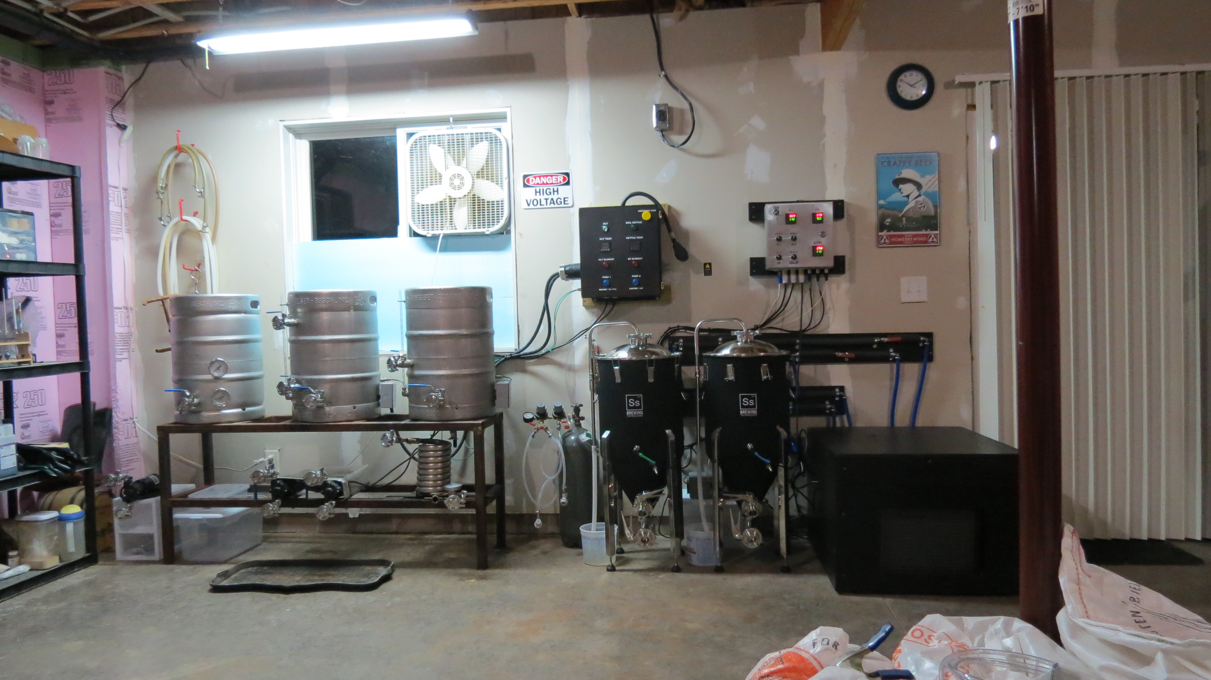
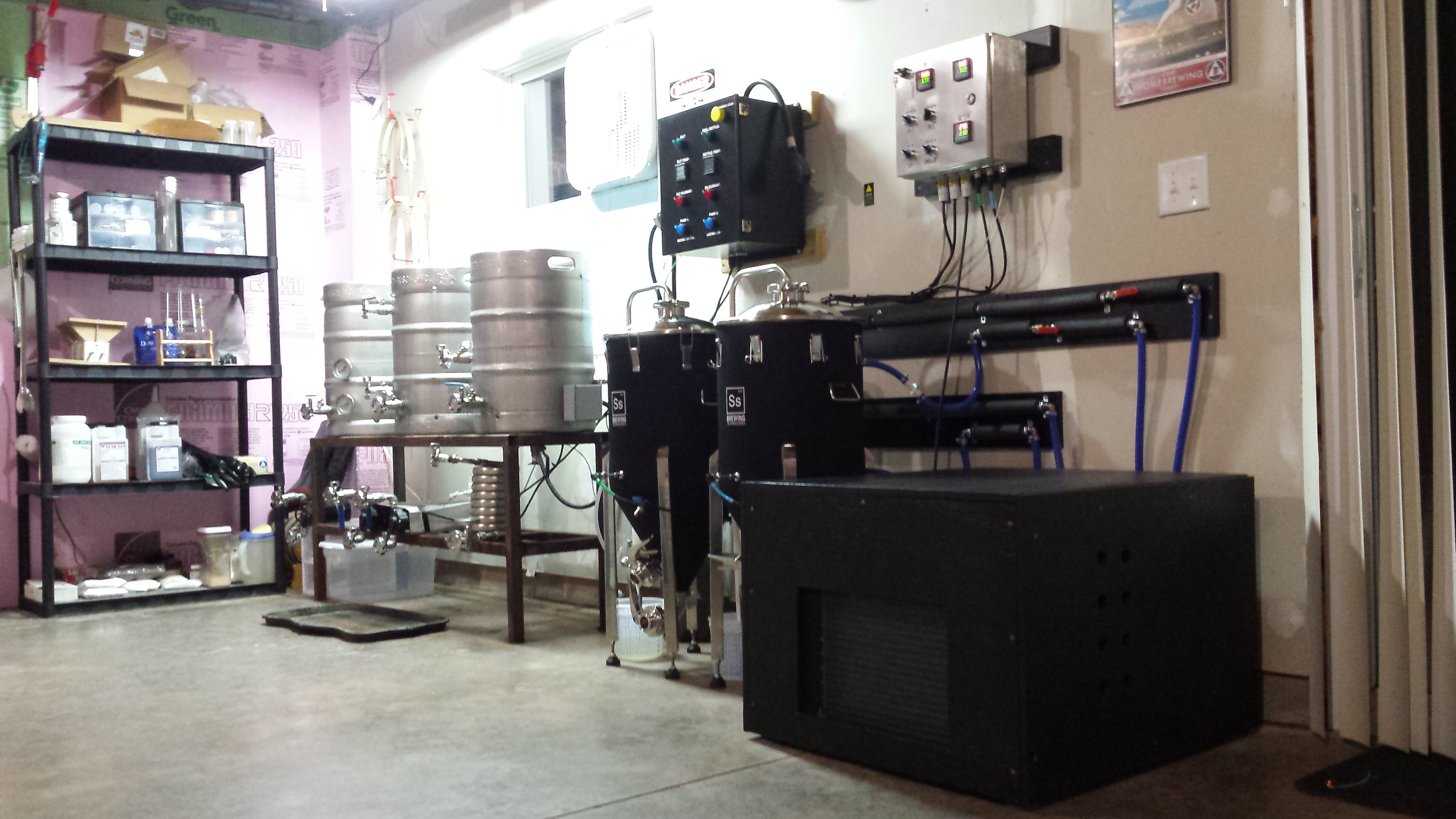
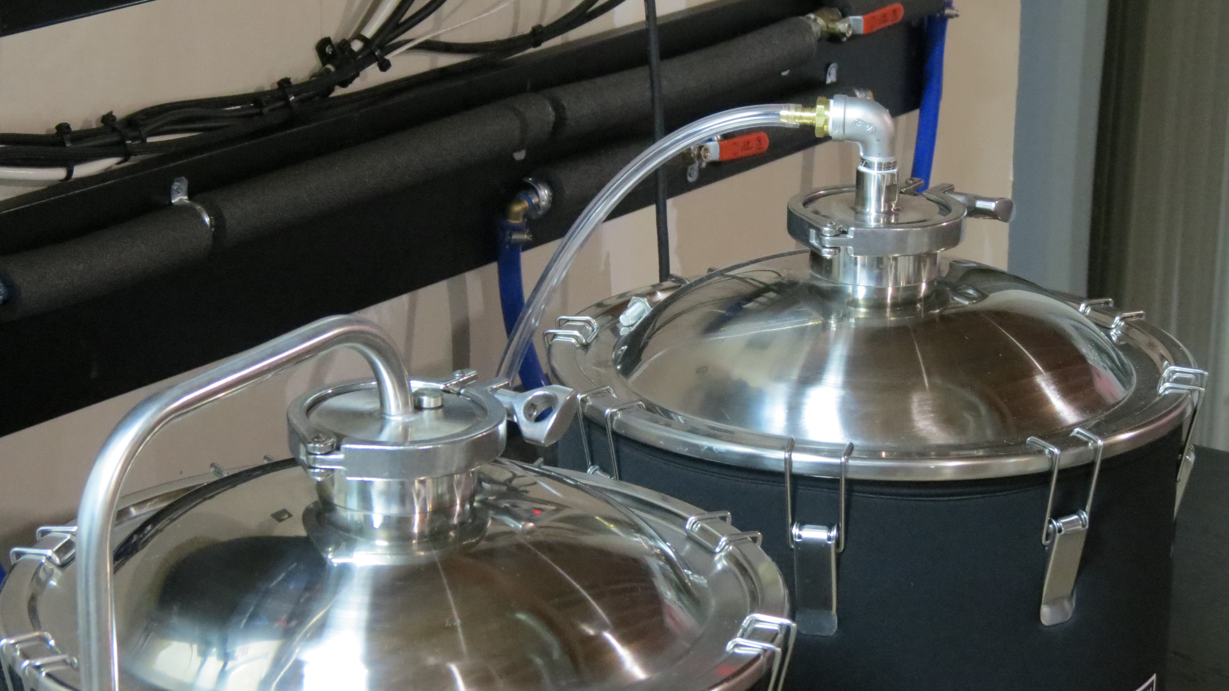
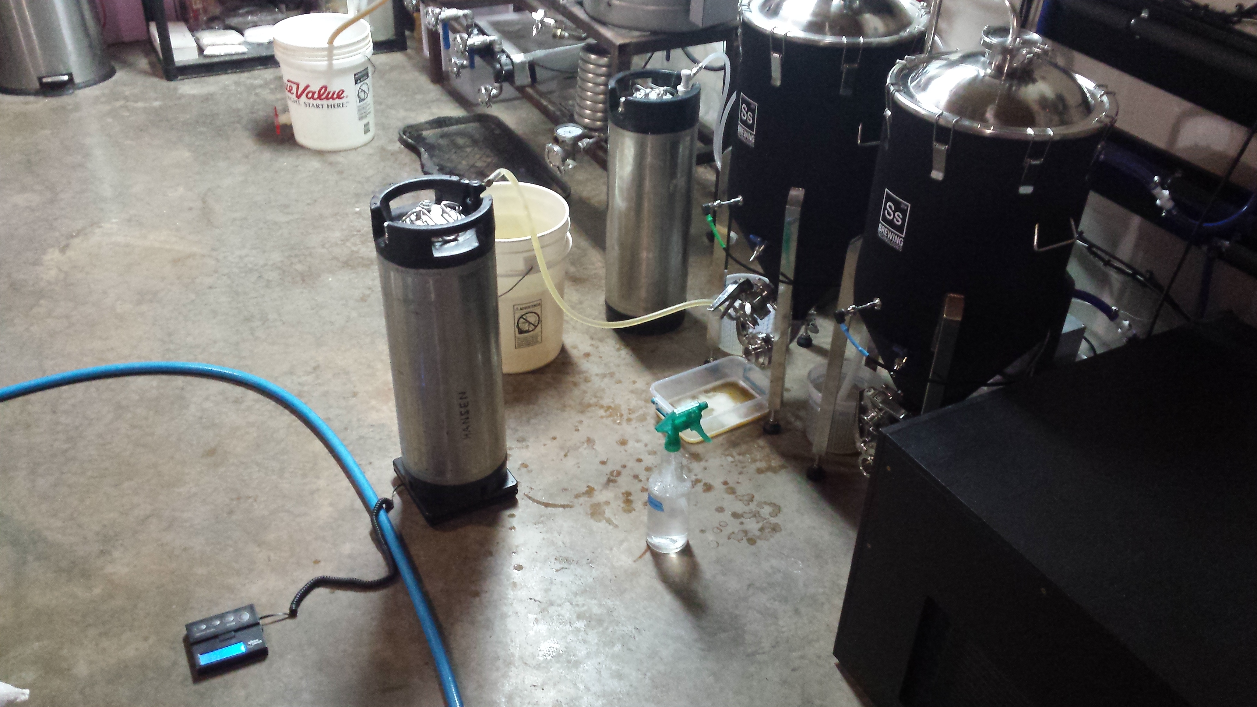
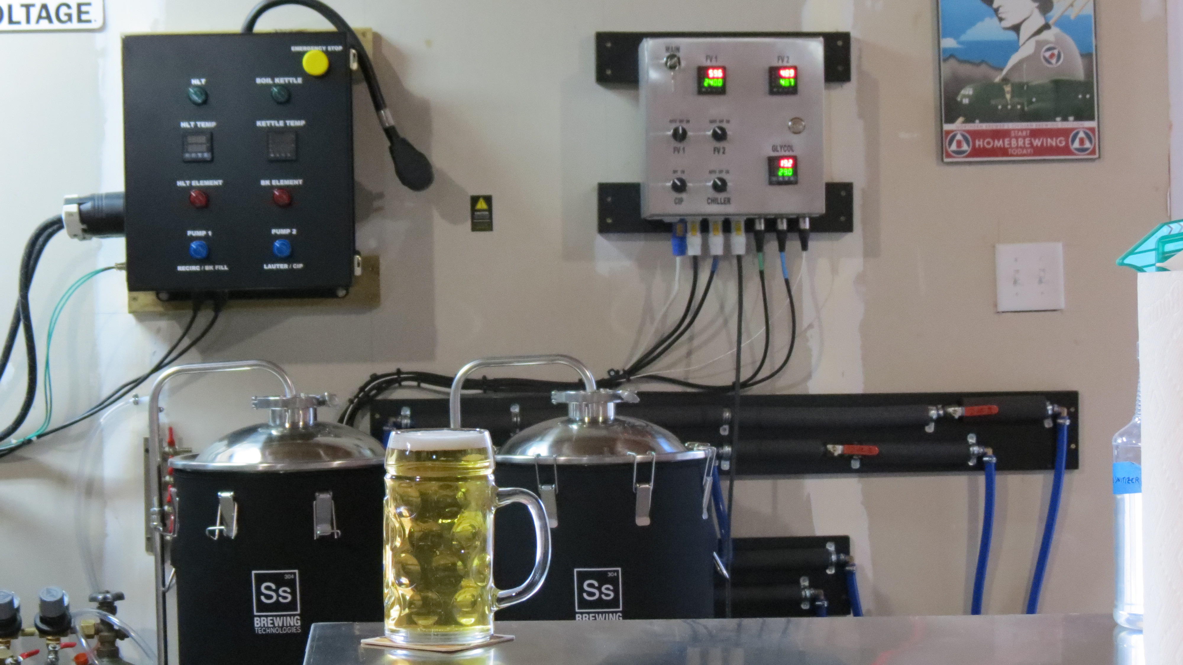
Finished project:
ZnTbfng.jpg

J9zAF2Z.jpg


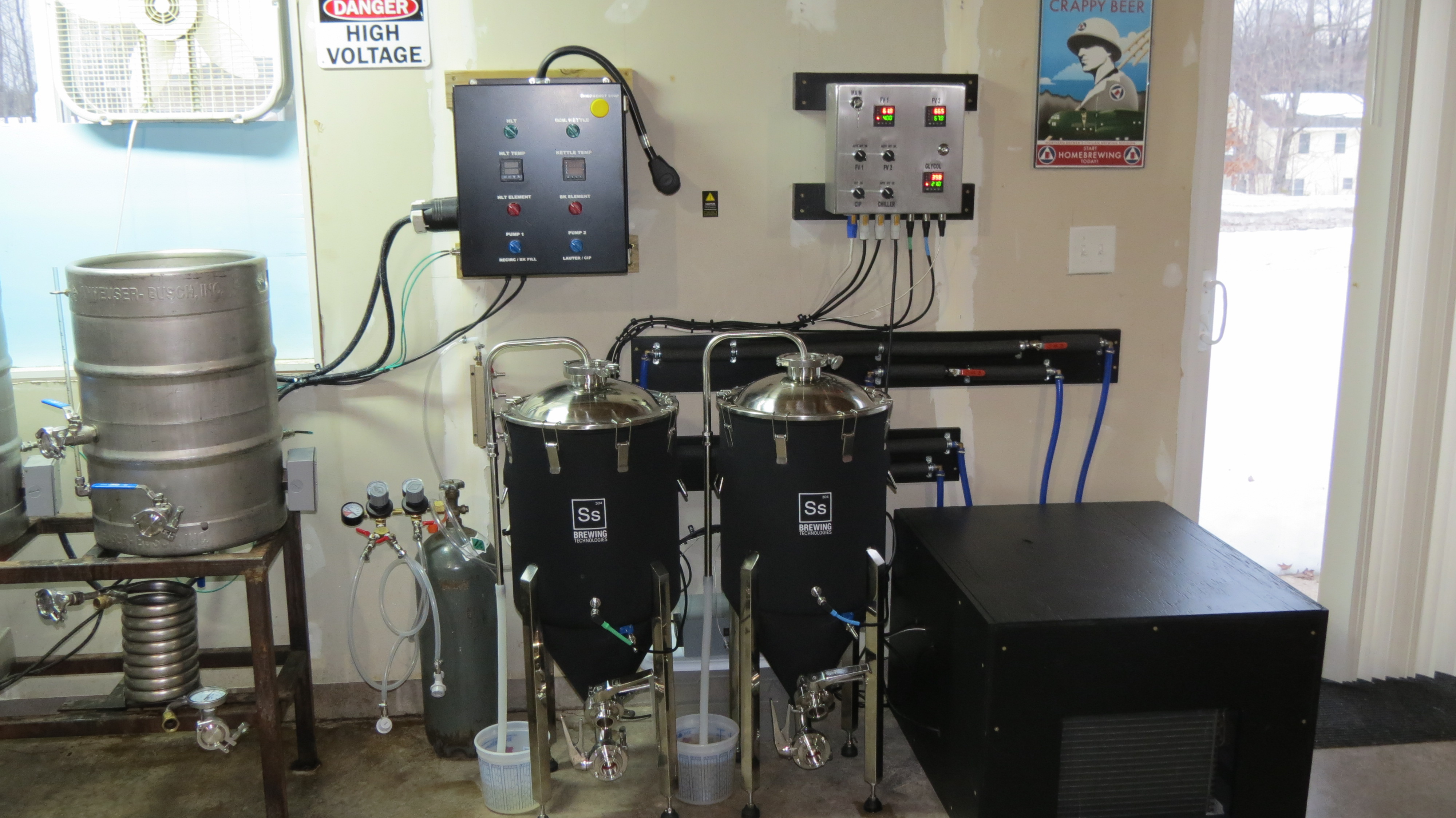
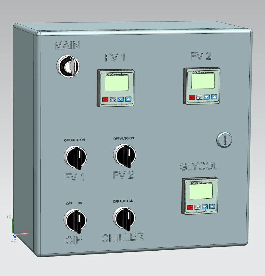
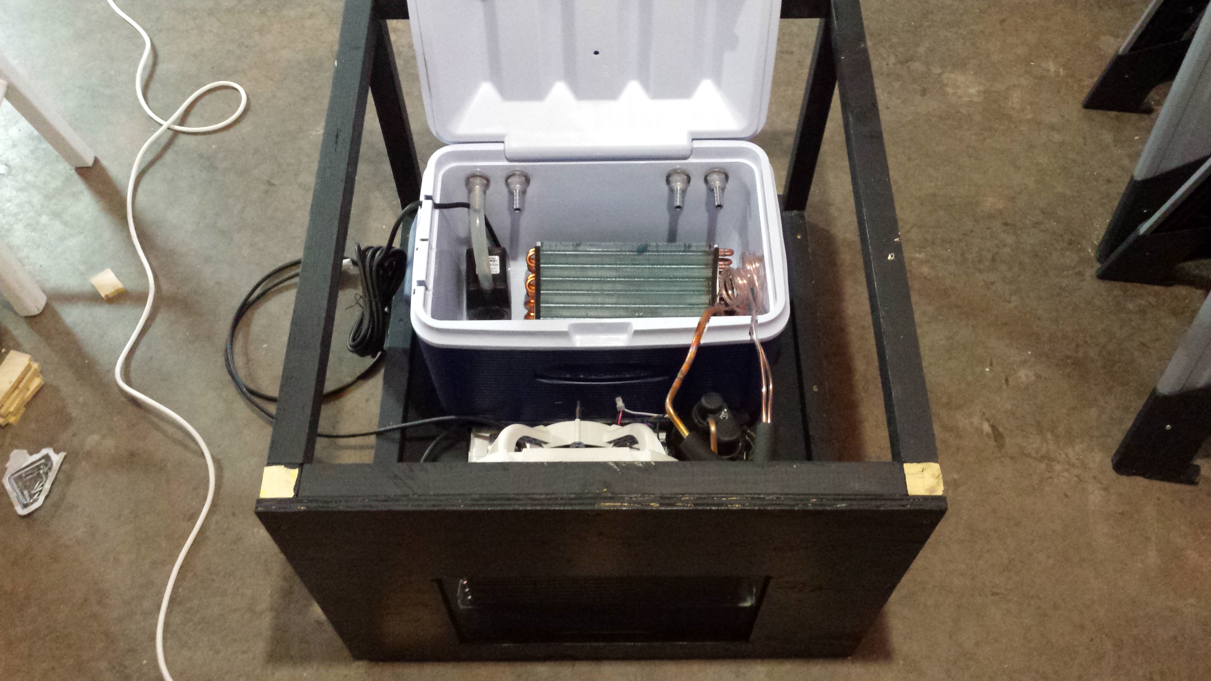
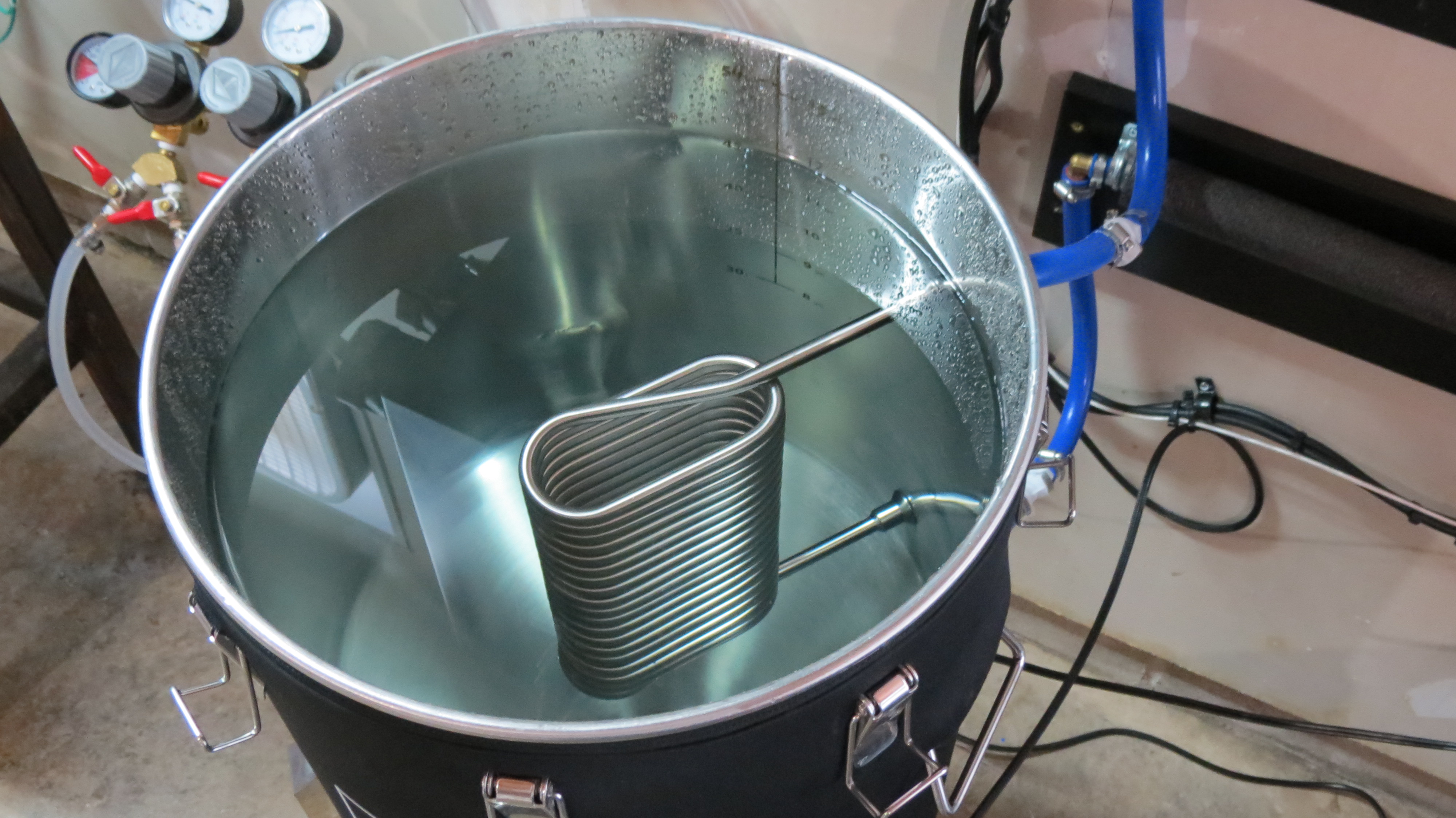
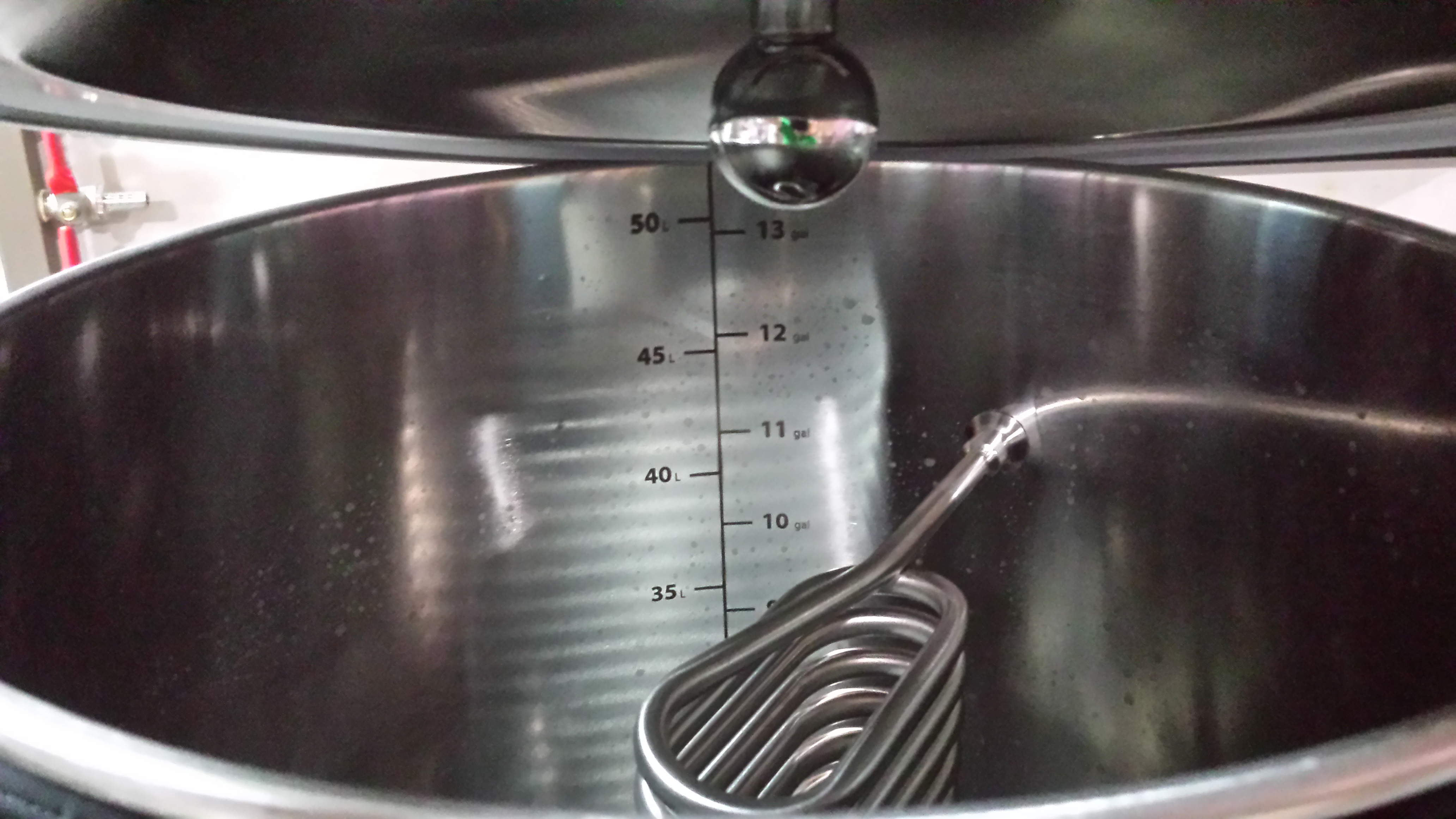
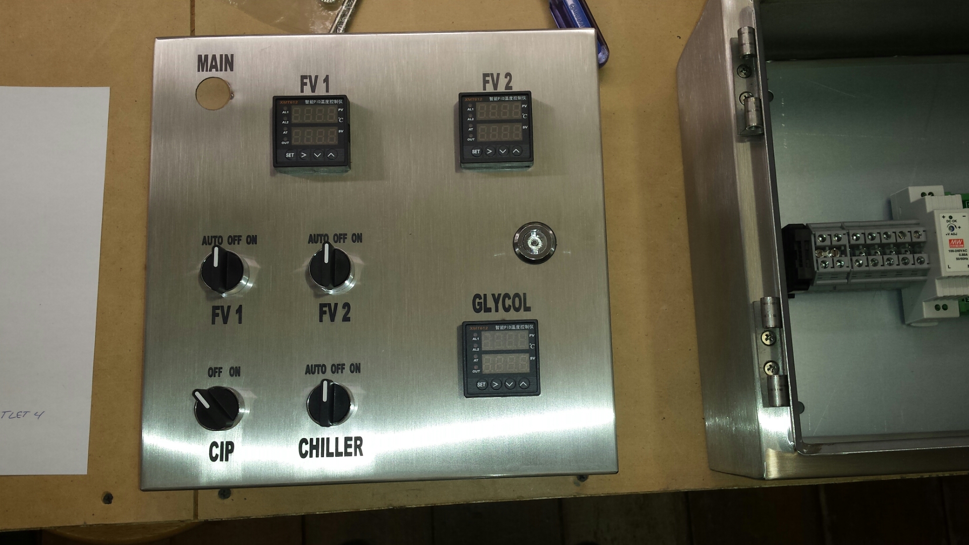
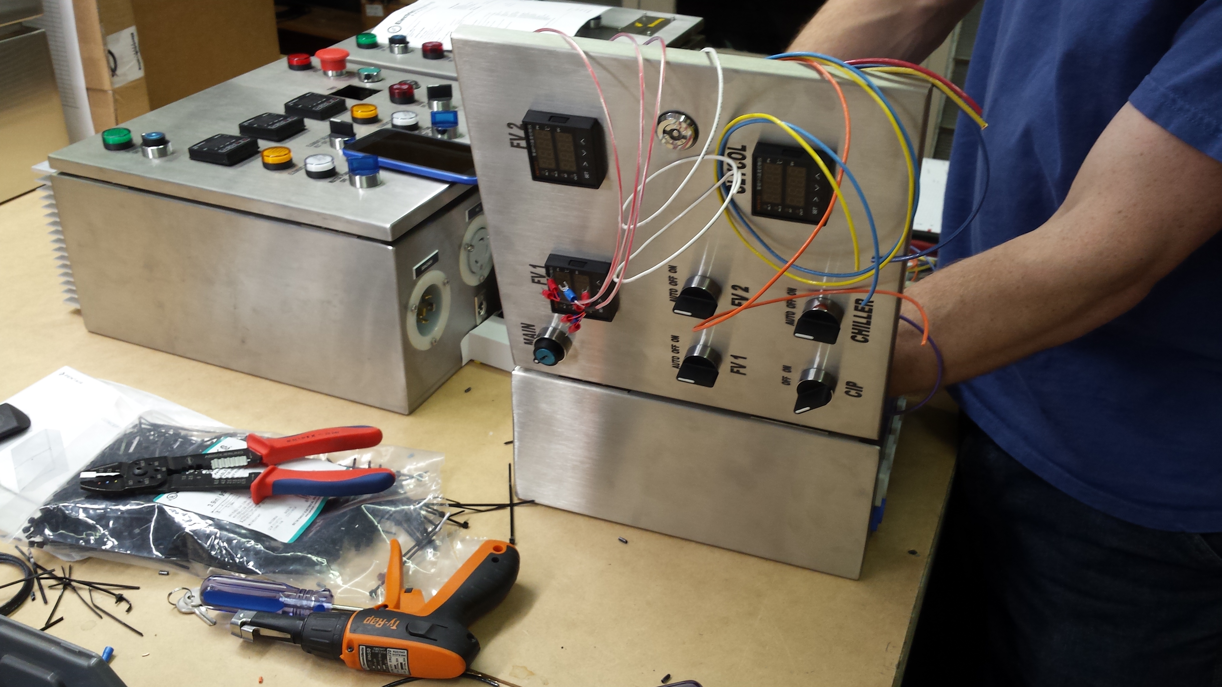
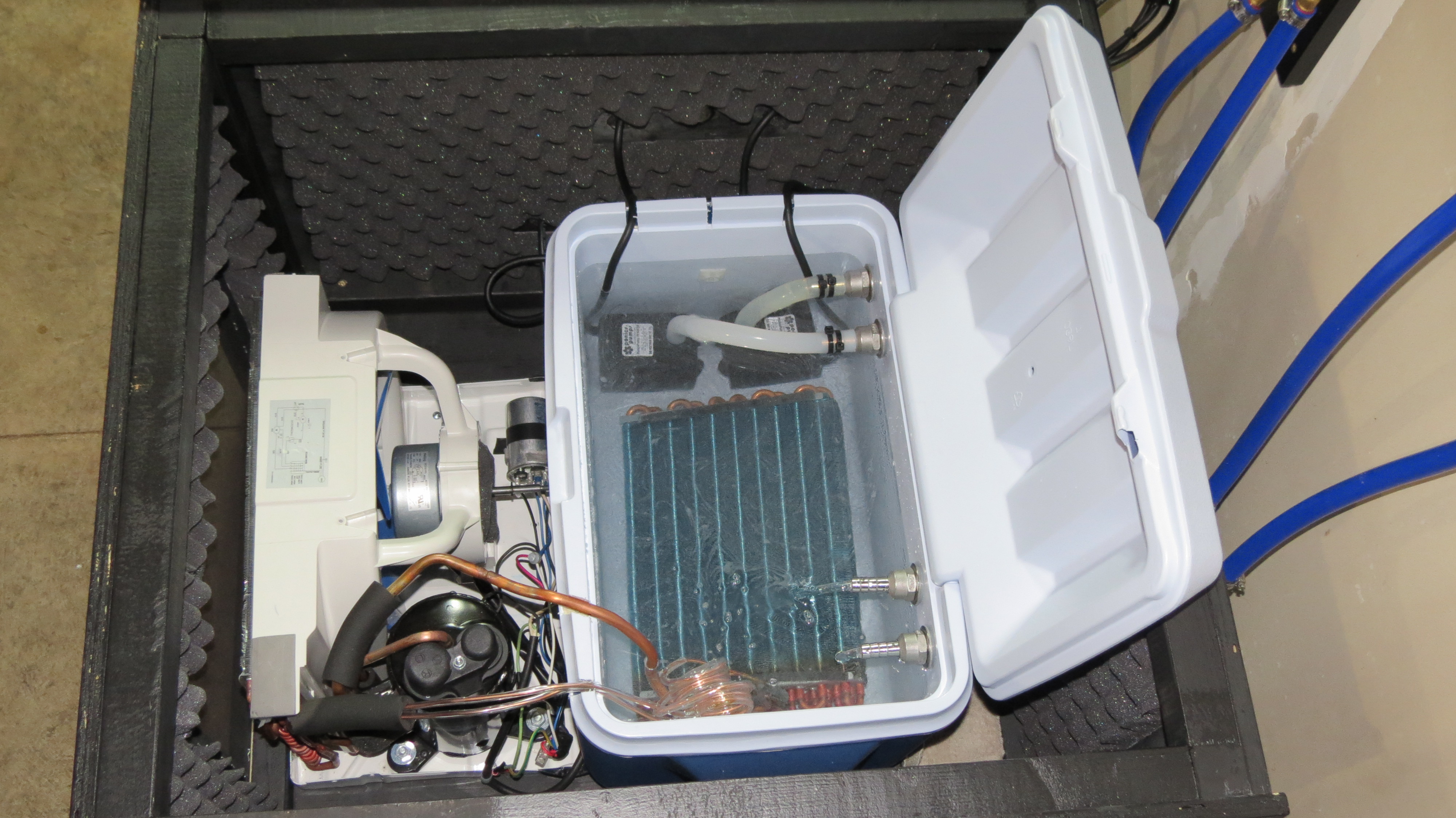
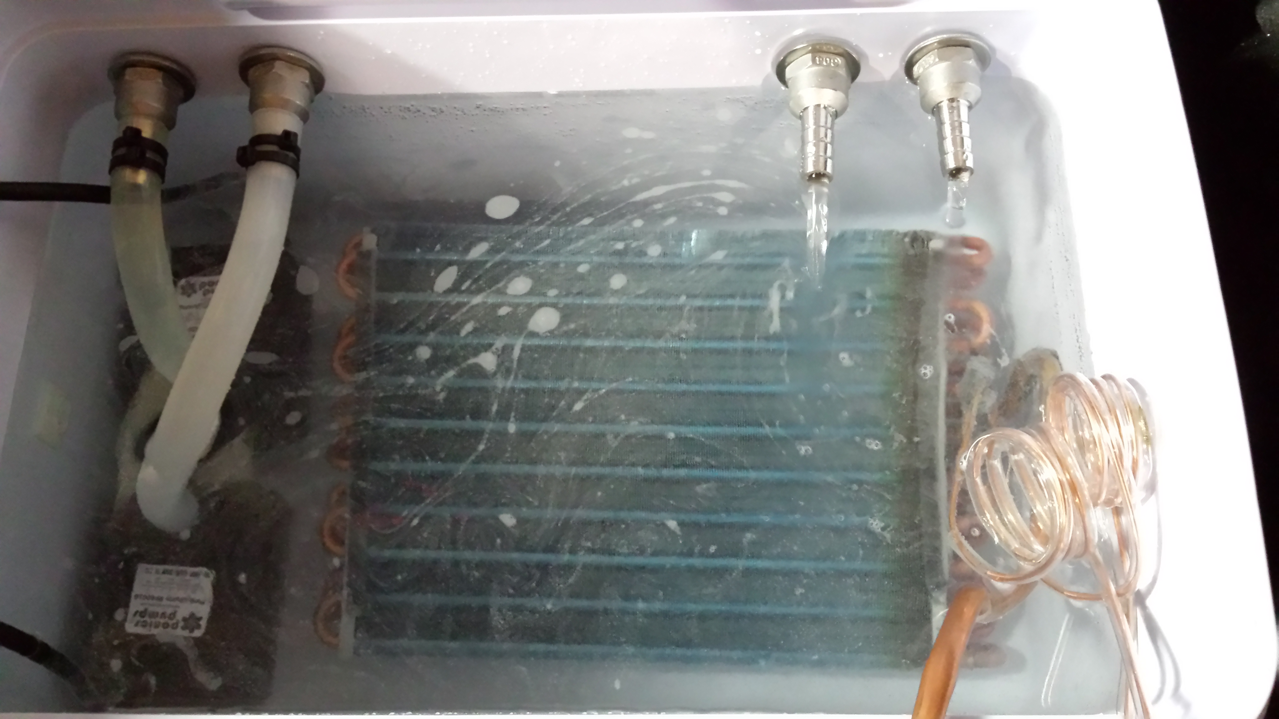
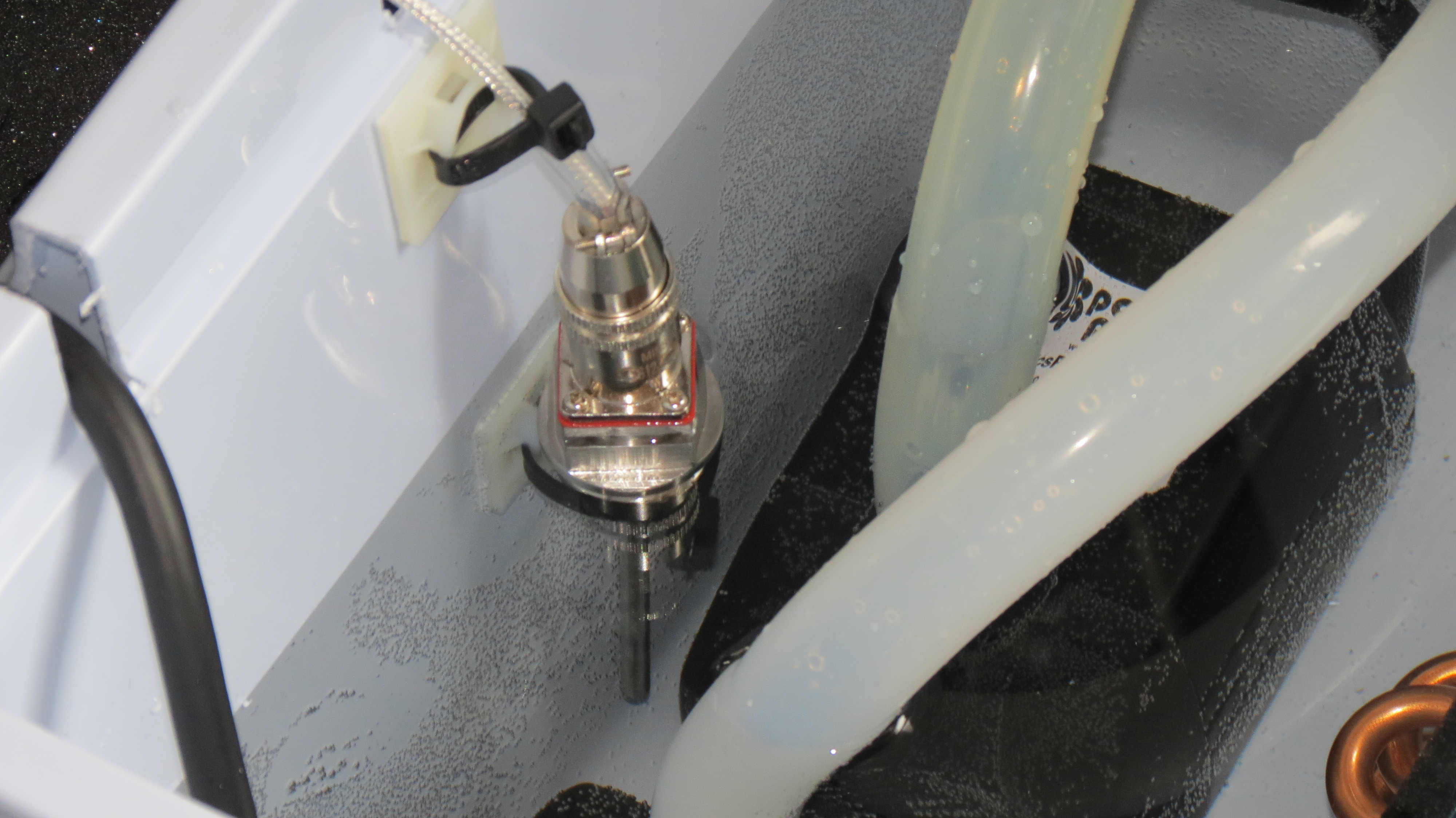
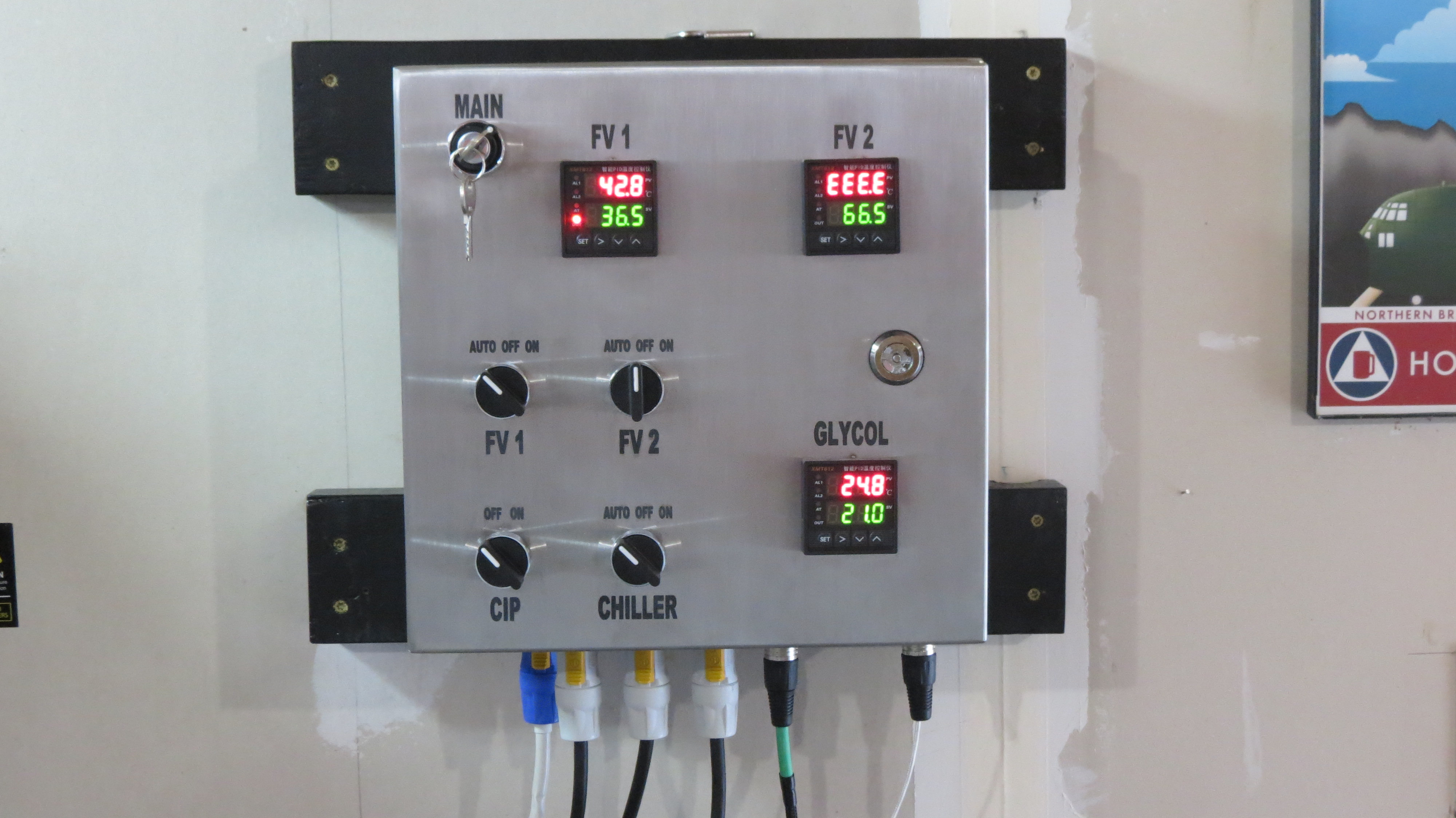
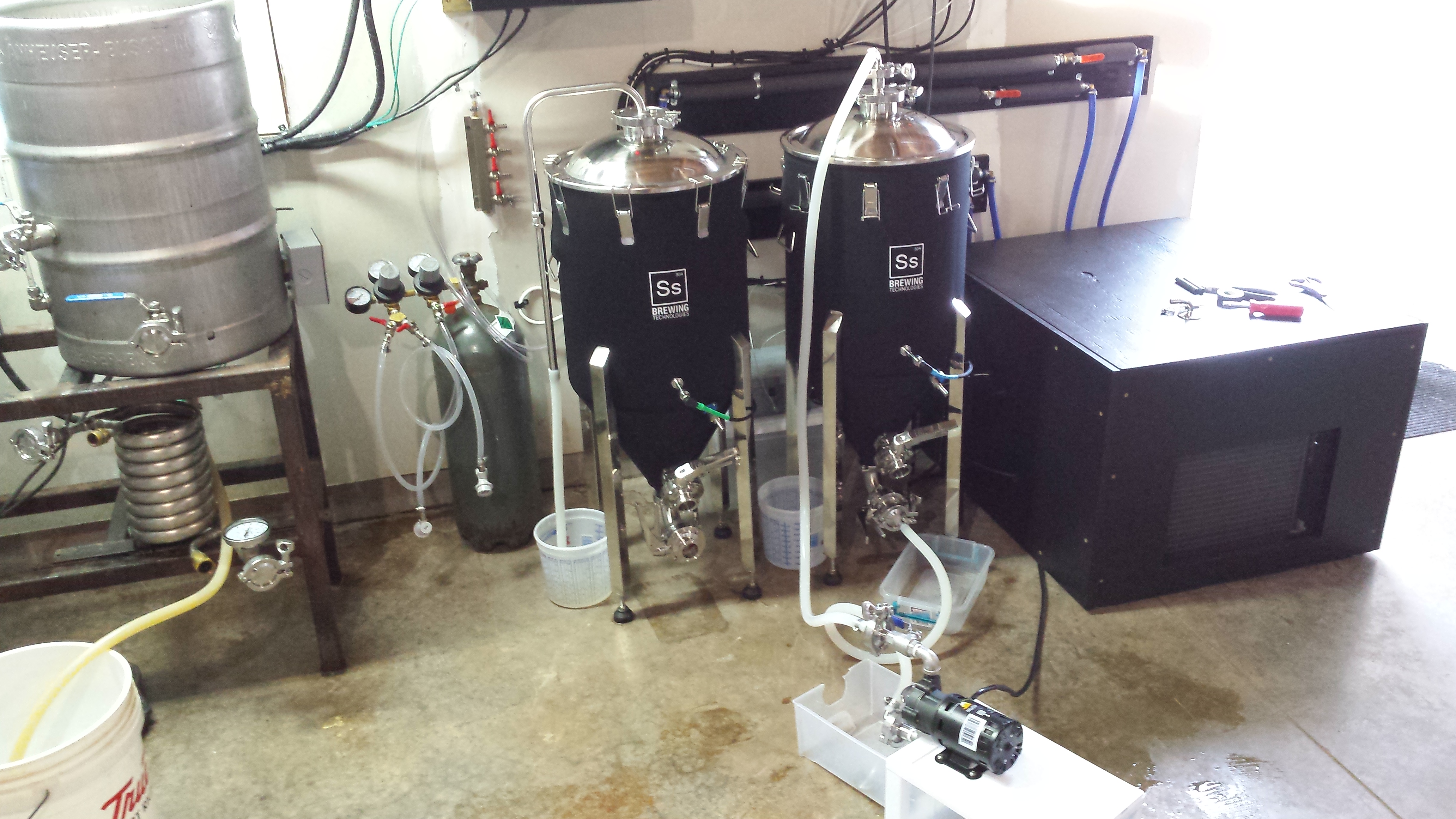
How it works: the evaporator from the A/C unit is submerged in a glycol solution inside a small cooler and is controlled by a PID unit in ON/OFF cooling mode. I chose one that has anti-short cycle delay to protect the compressor. The glycol PID gets temperature data from an RTD in the glycol solution. There are two submersible pond pumps - one for each fermentor - that are each controlled by a PID in ON/OFF mode. Temperature data is sent via RTDs in the thermowell on the conicals. When the beer reaches a certain temperature (SV+Hy), the PID turns on the pump, which pumps ~19F glycol solution through a coil in the fermentor, and back into the cooler. When the glycol temperature reaches upper control limit, the PID turns on the compressor/fan and cools the solution as needed.

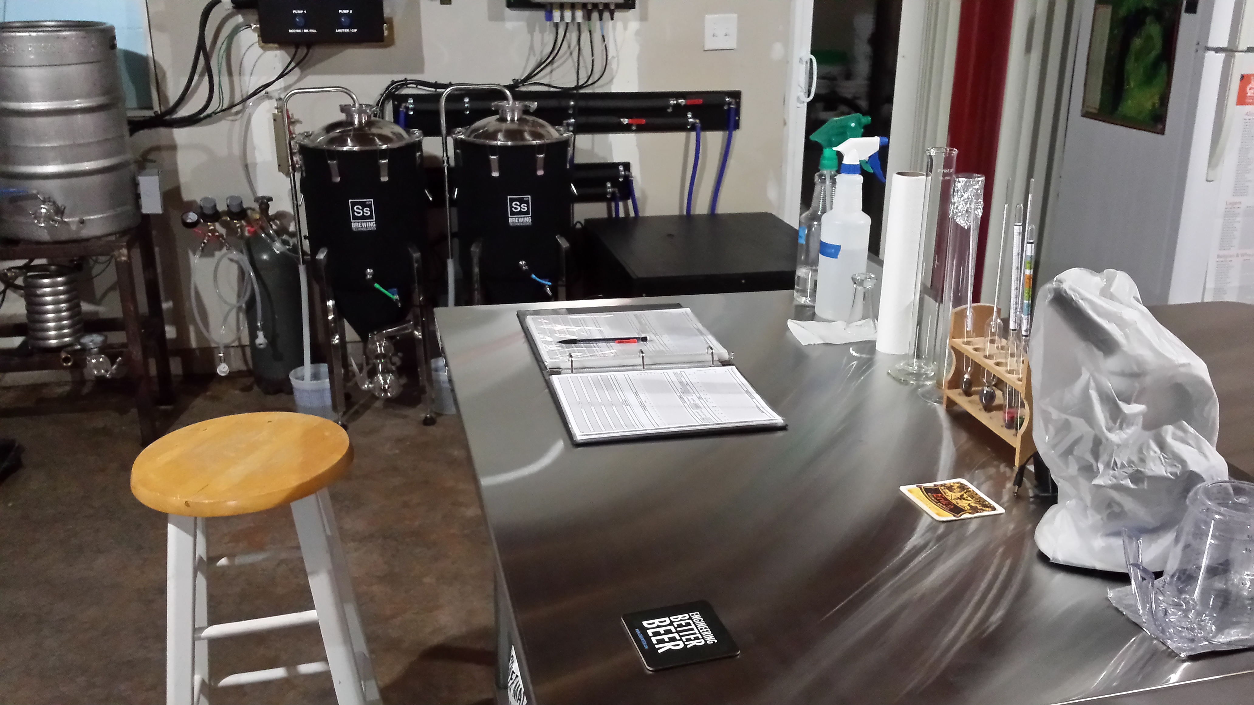
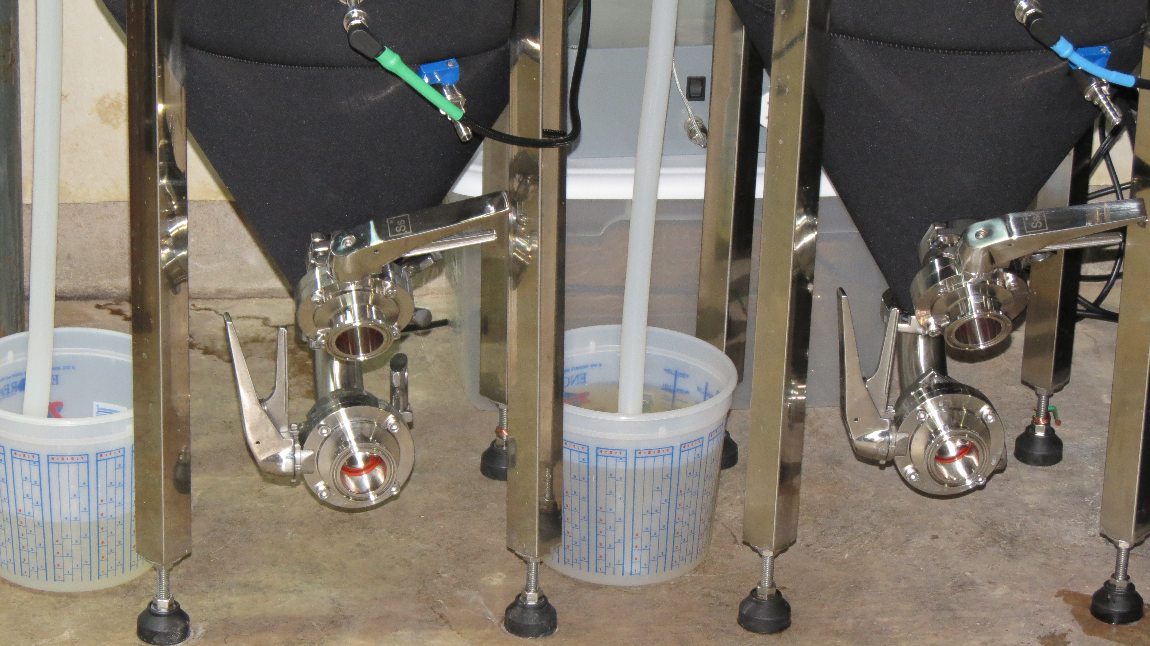
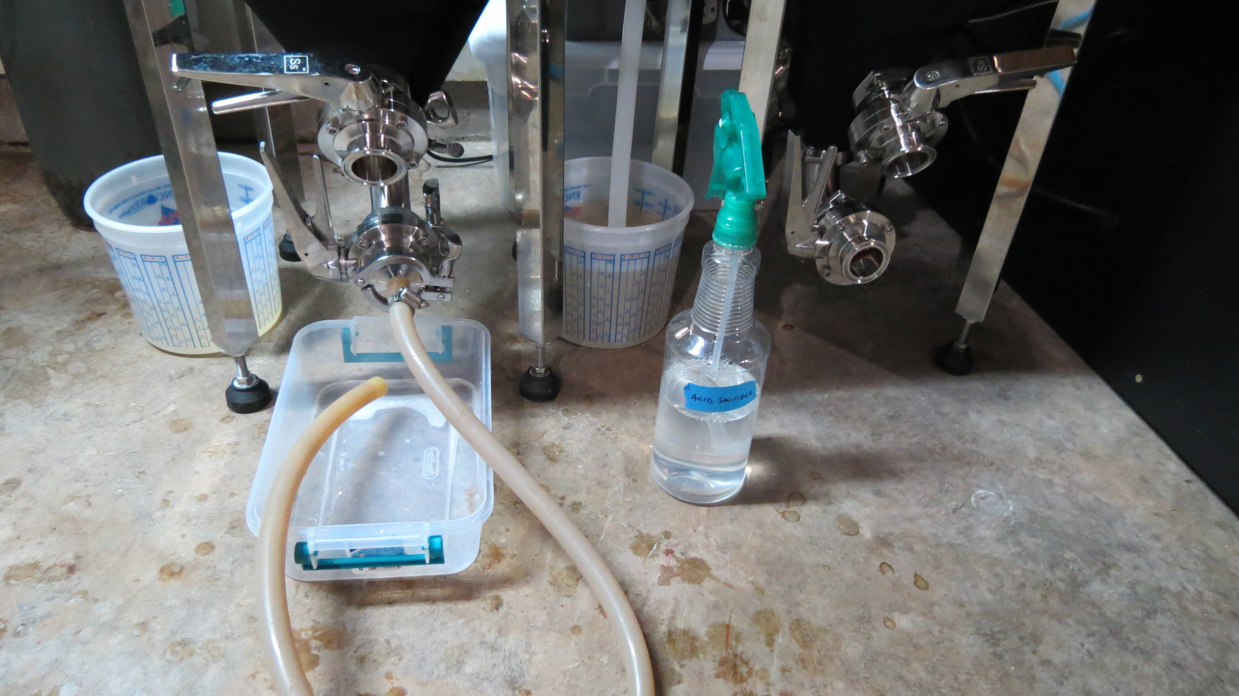
I also opted to include a 120VAC switched outlet on the panel for a CIP pump. With that, I can do all the CIP & SIP required for the conicals without having to use an extension cord or have a separate switch box - it's all in the fermentation control panel!

A big shout out to Ryan at eBrewSupply for his help. He was generous with sharing his knowledge, wiring the panel, and helping me acquire some equipment.

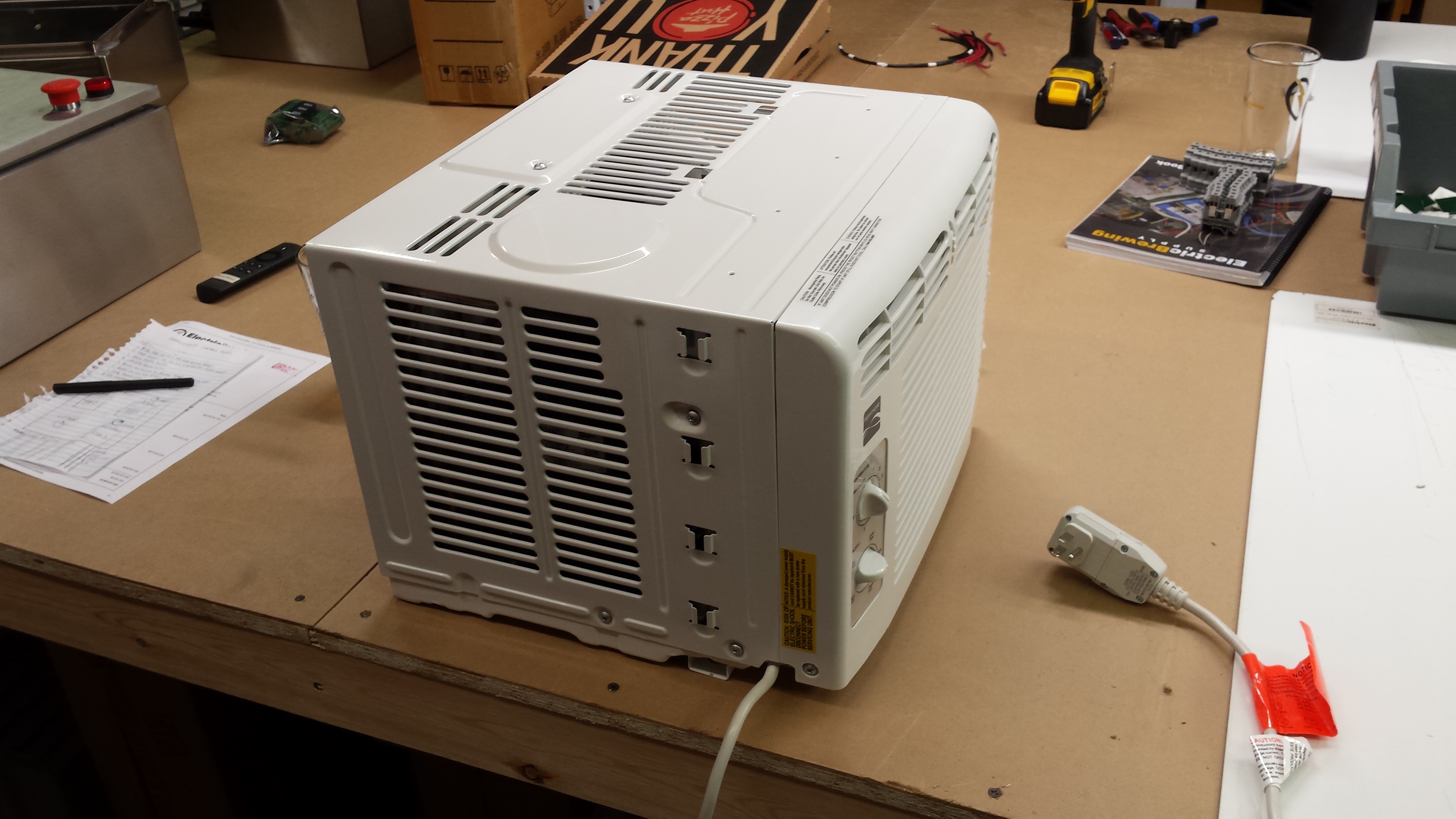
I started with a 5,000 BTU window A/C unit. Got it for about $130 at Sears.

9XJYaHt.jpg


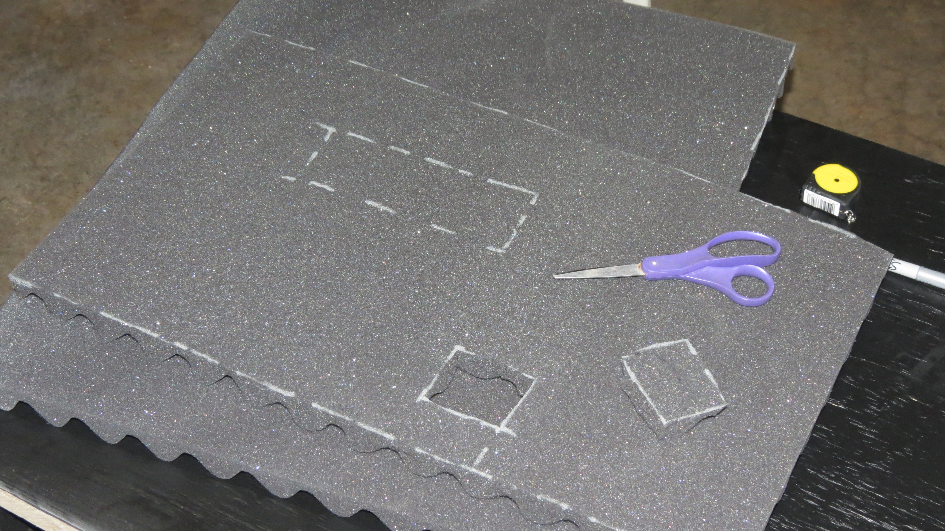
Then tear it down and discard any unused parts:
uUmcu9g.jpg


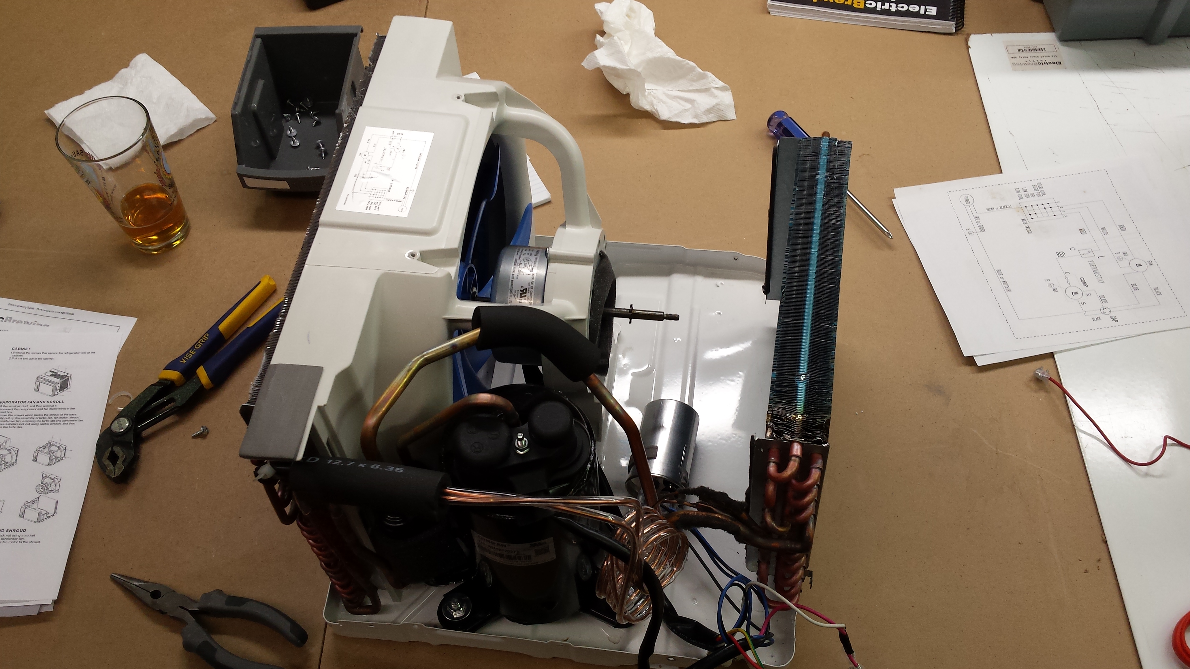
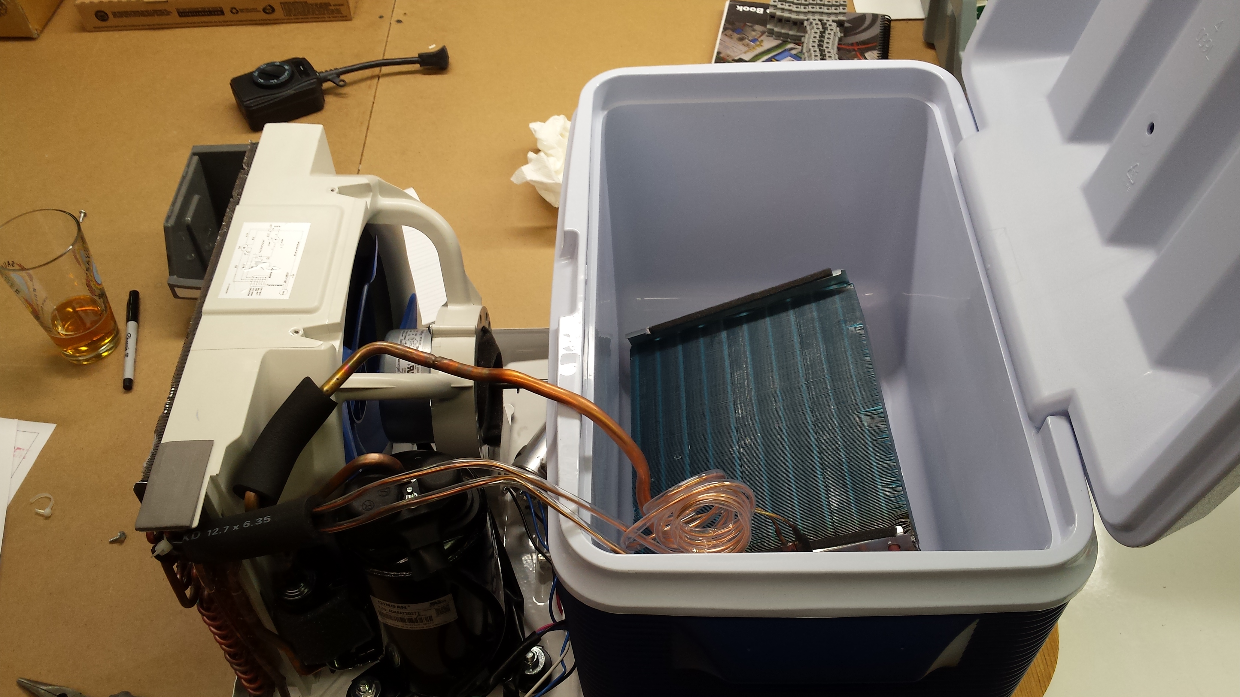
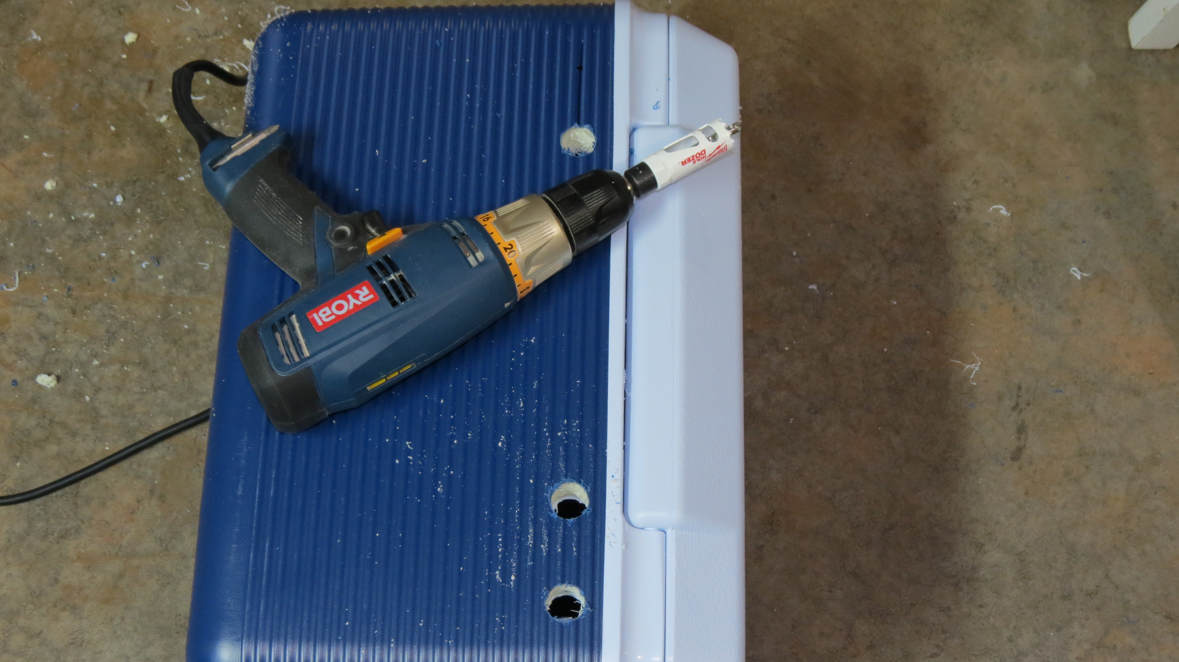
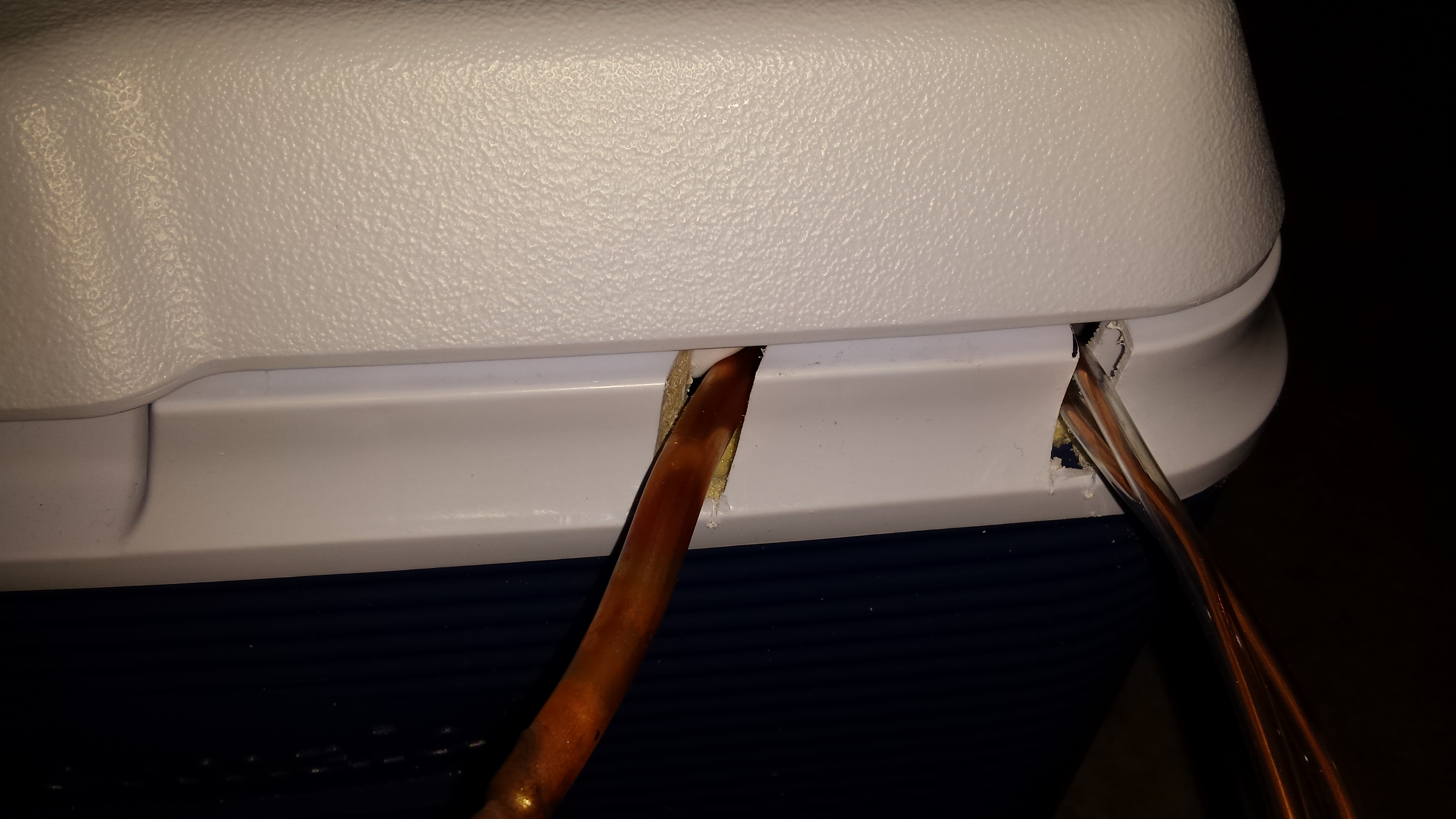
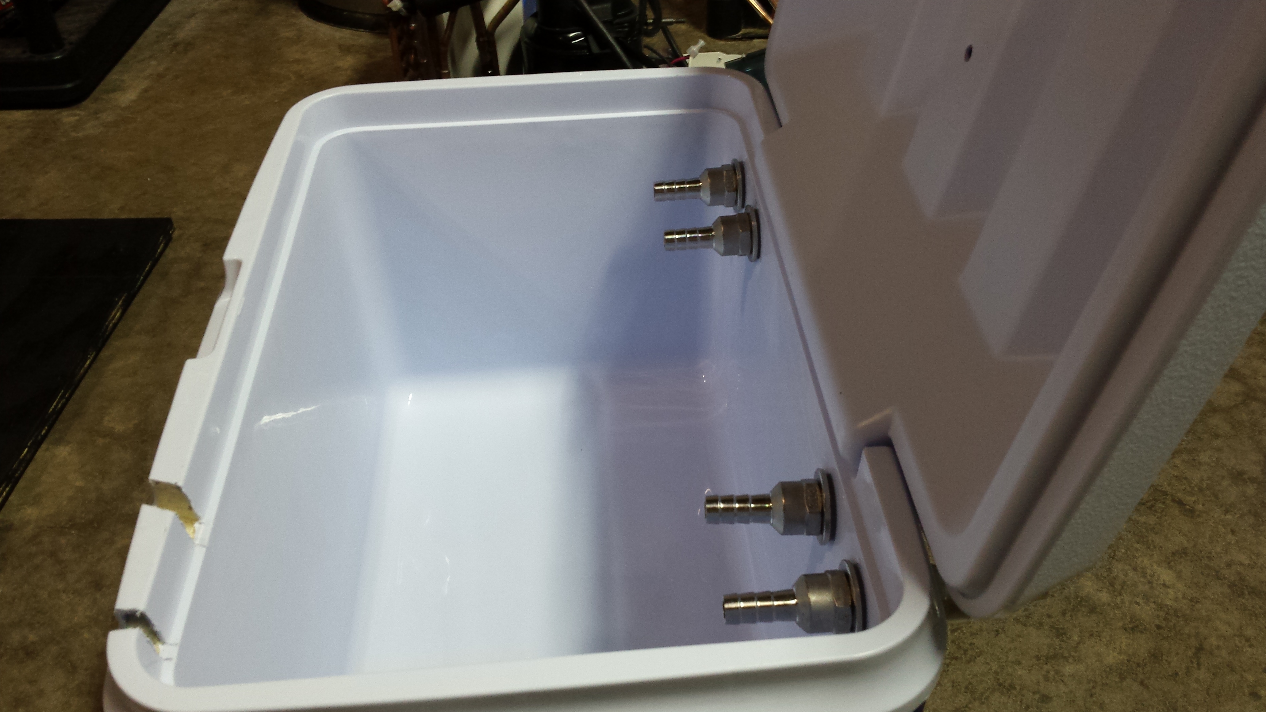
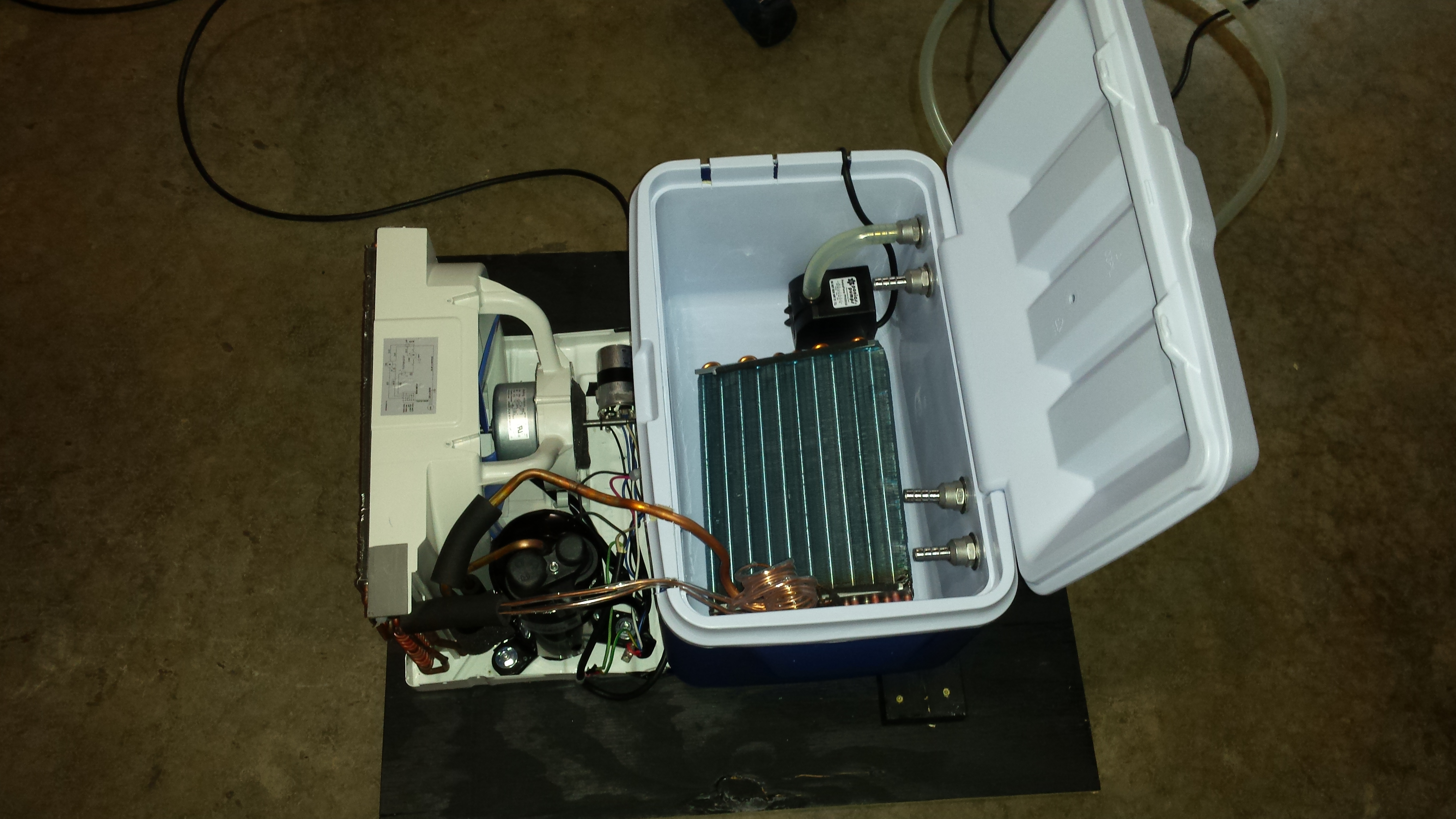
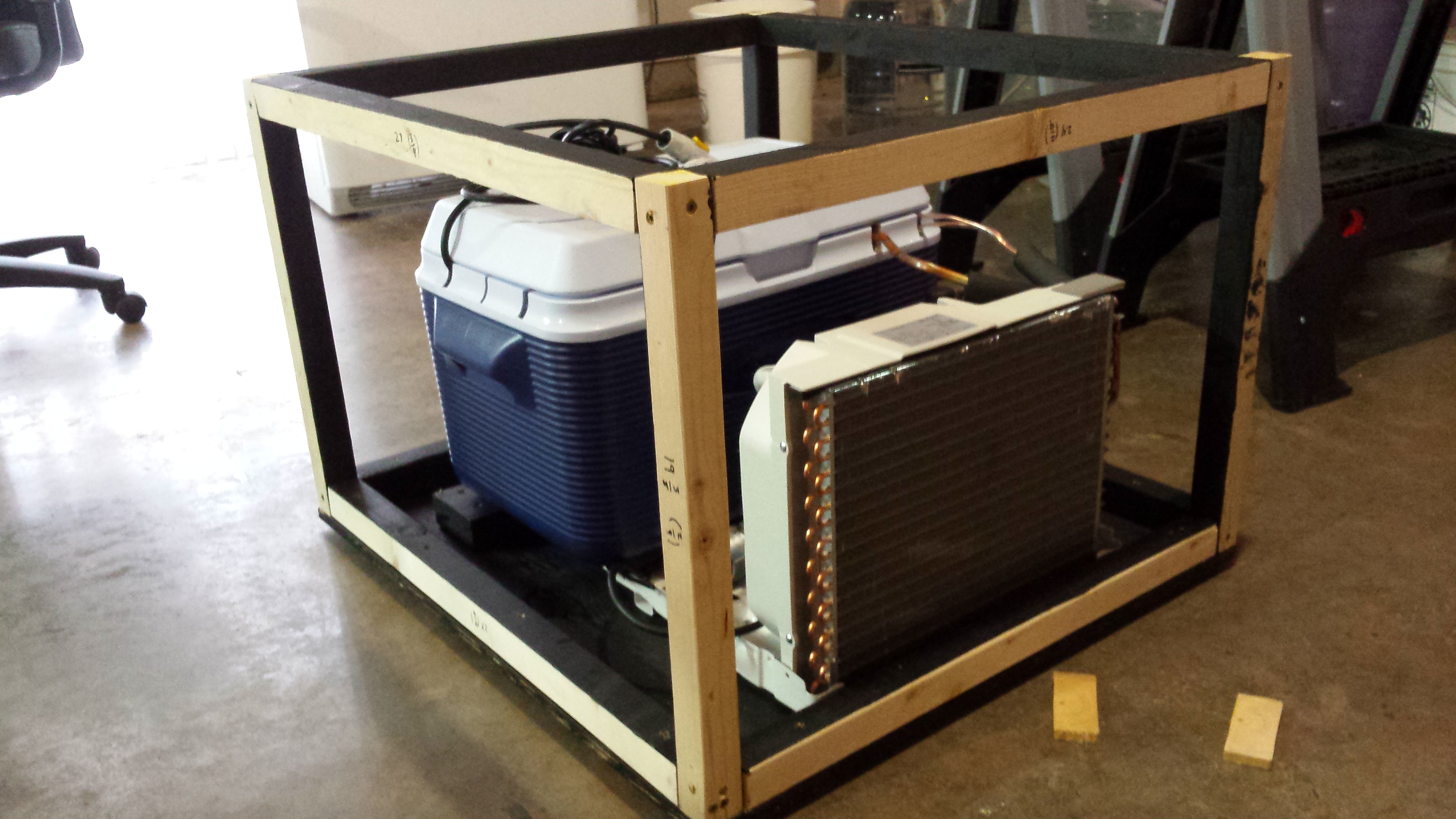
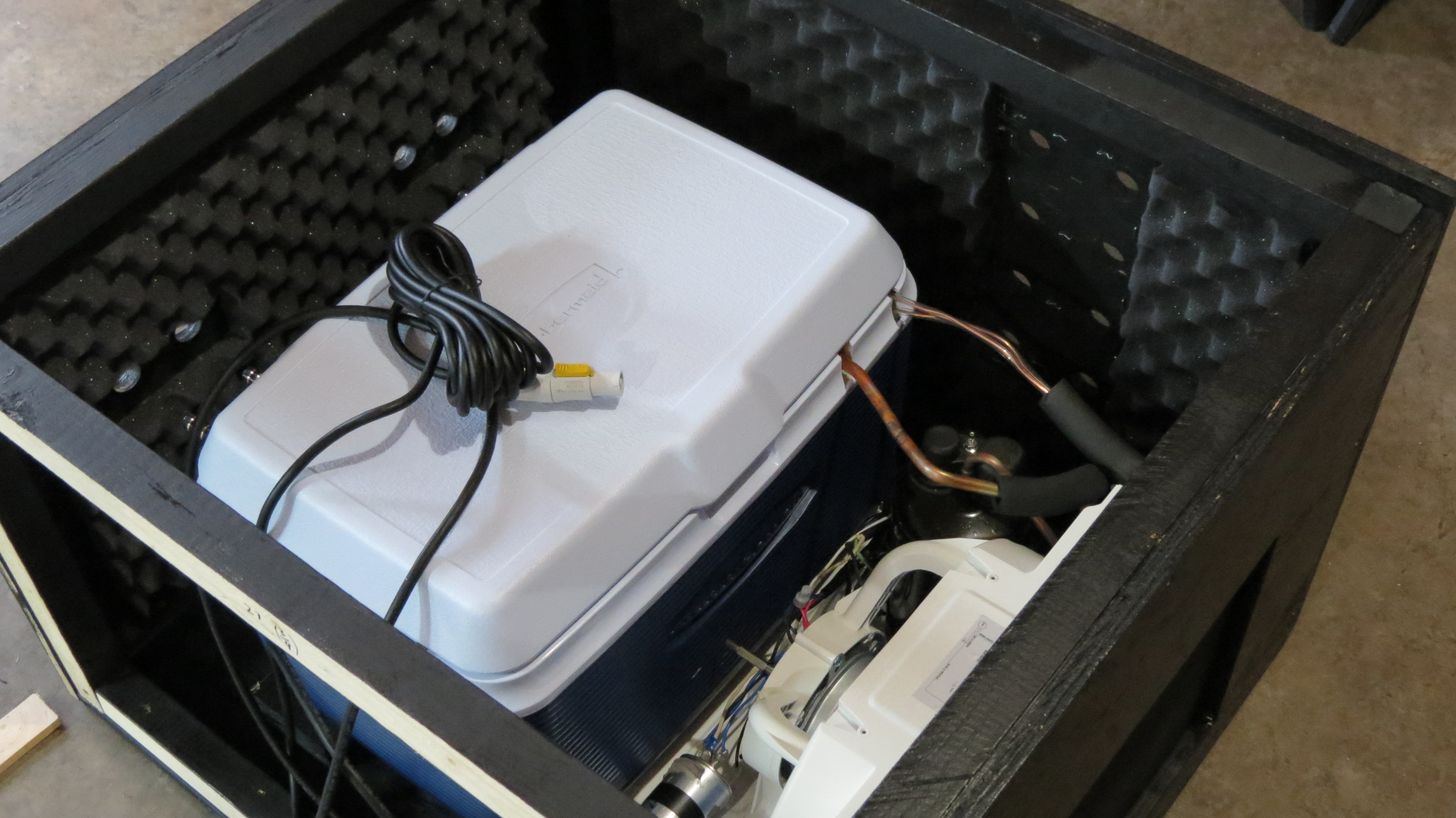
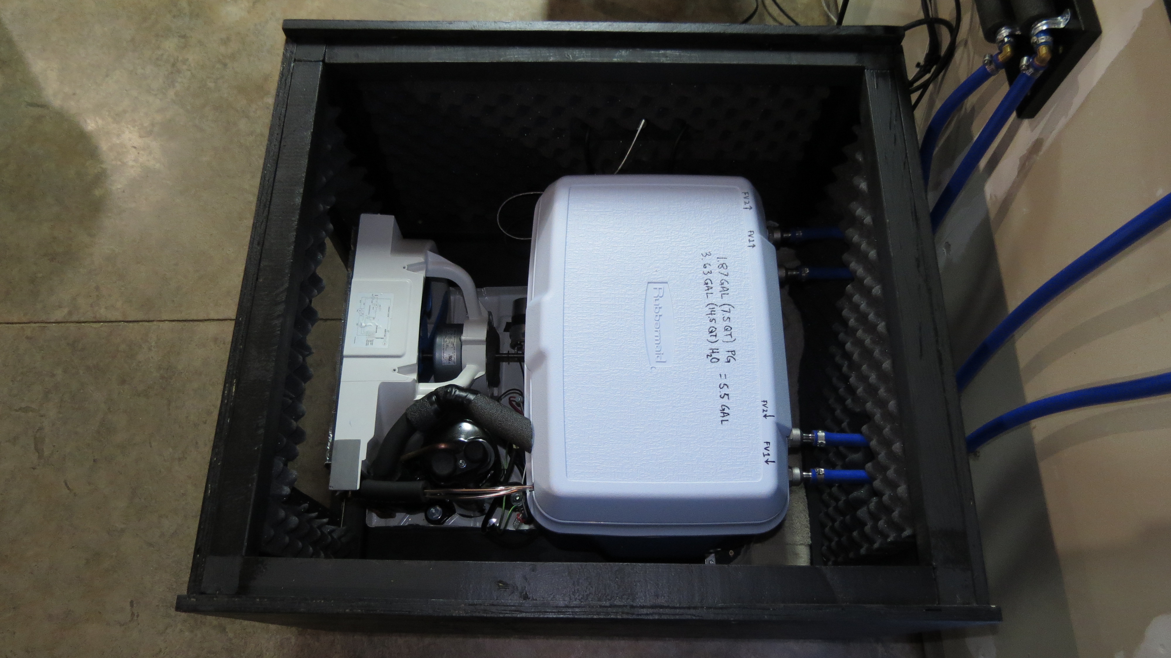
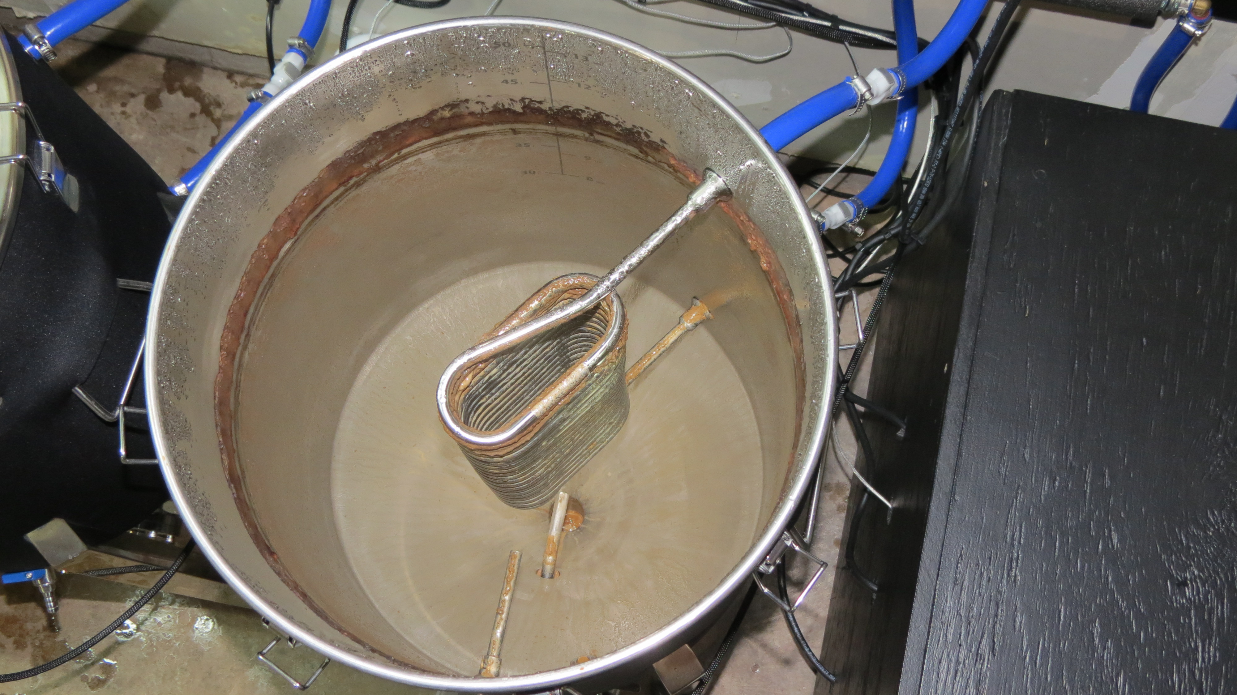
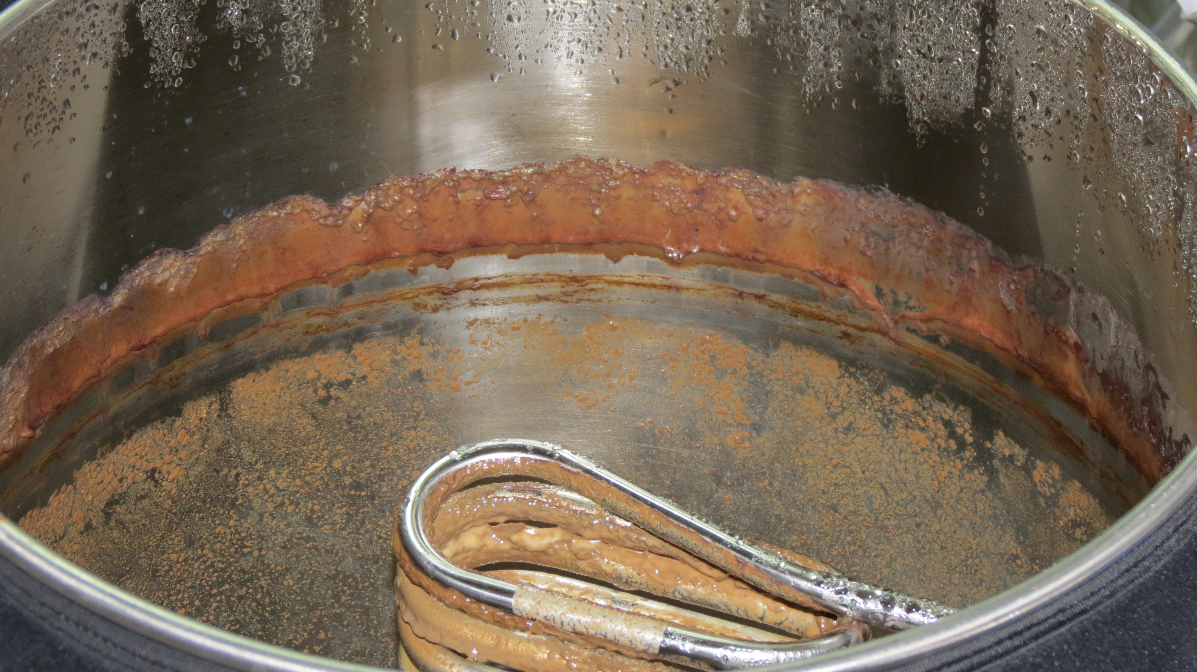
Carefully extend the evaporator into the cooler. You don't want to stress or kink the copper lines. I used a 34 quart cooler, which will be filled to about 5.5 gallons of glycol solution.
vIeJ9nX.jpg


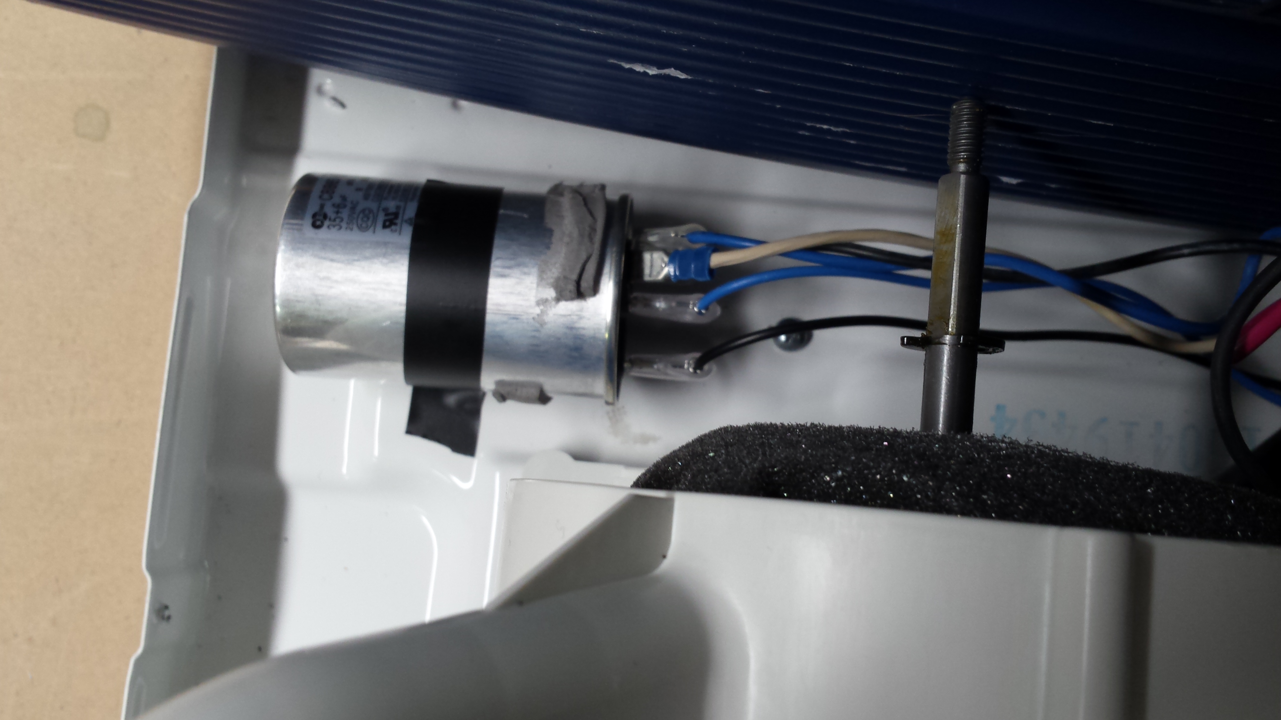
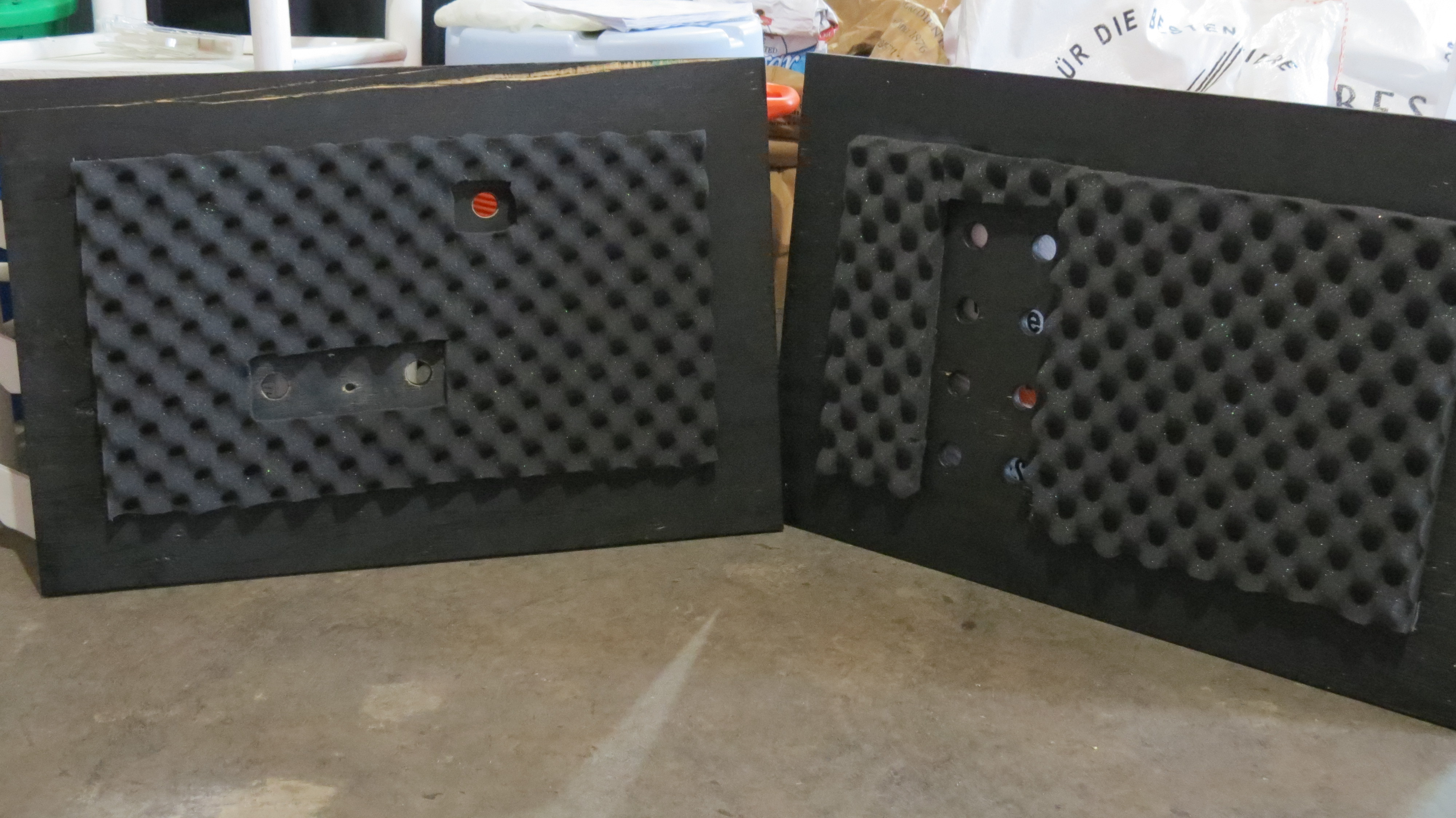
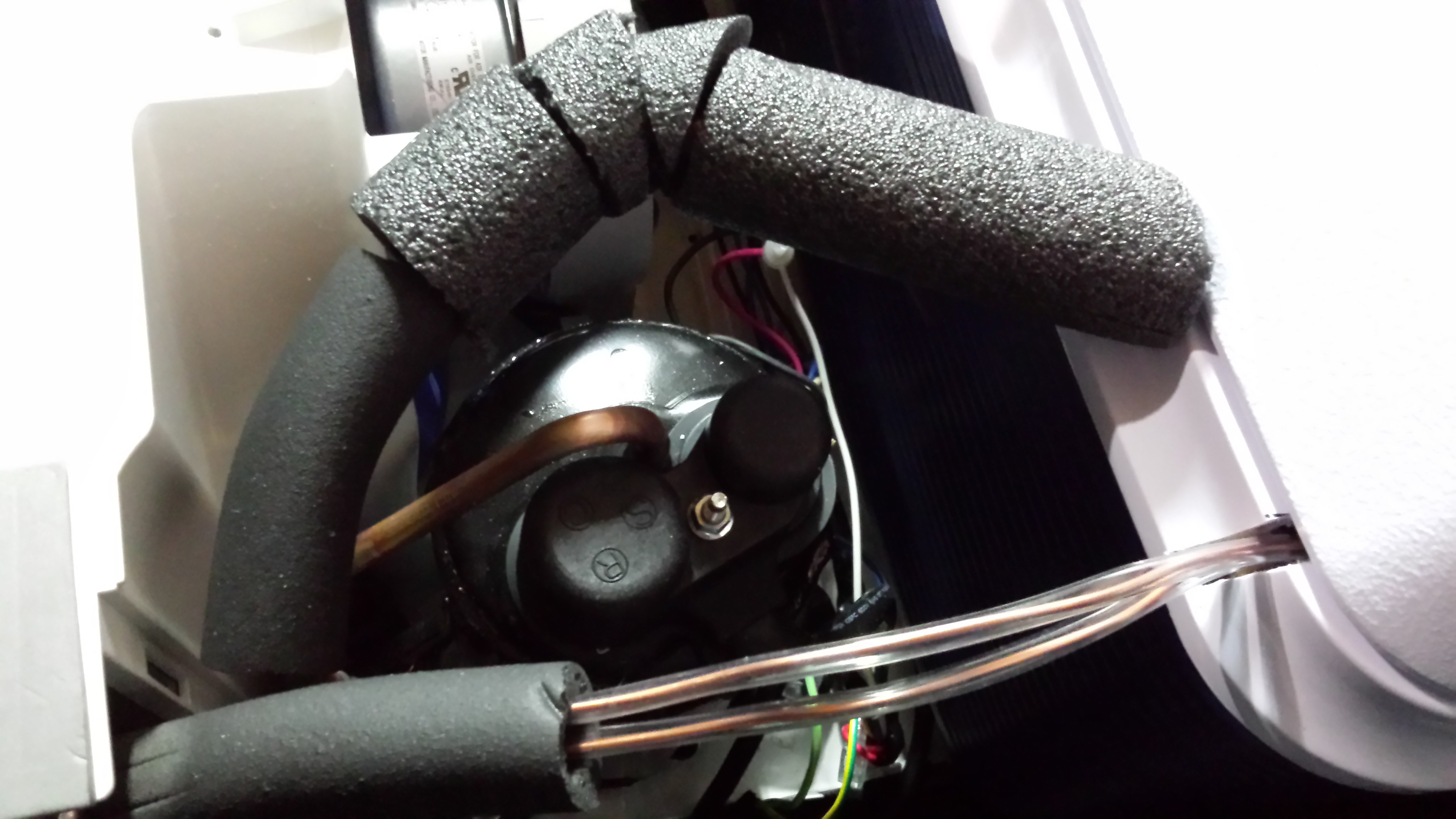
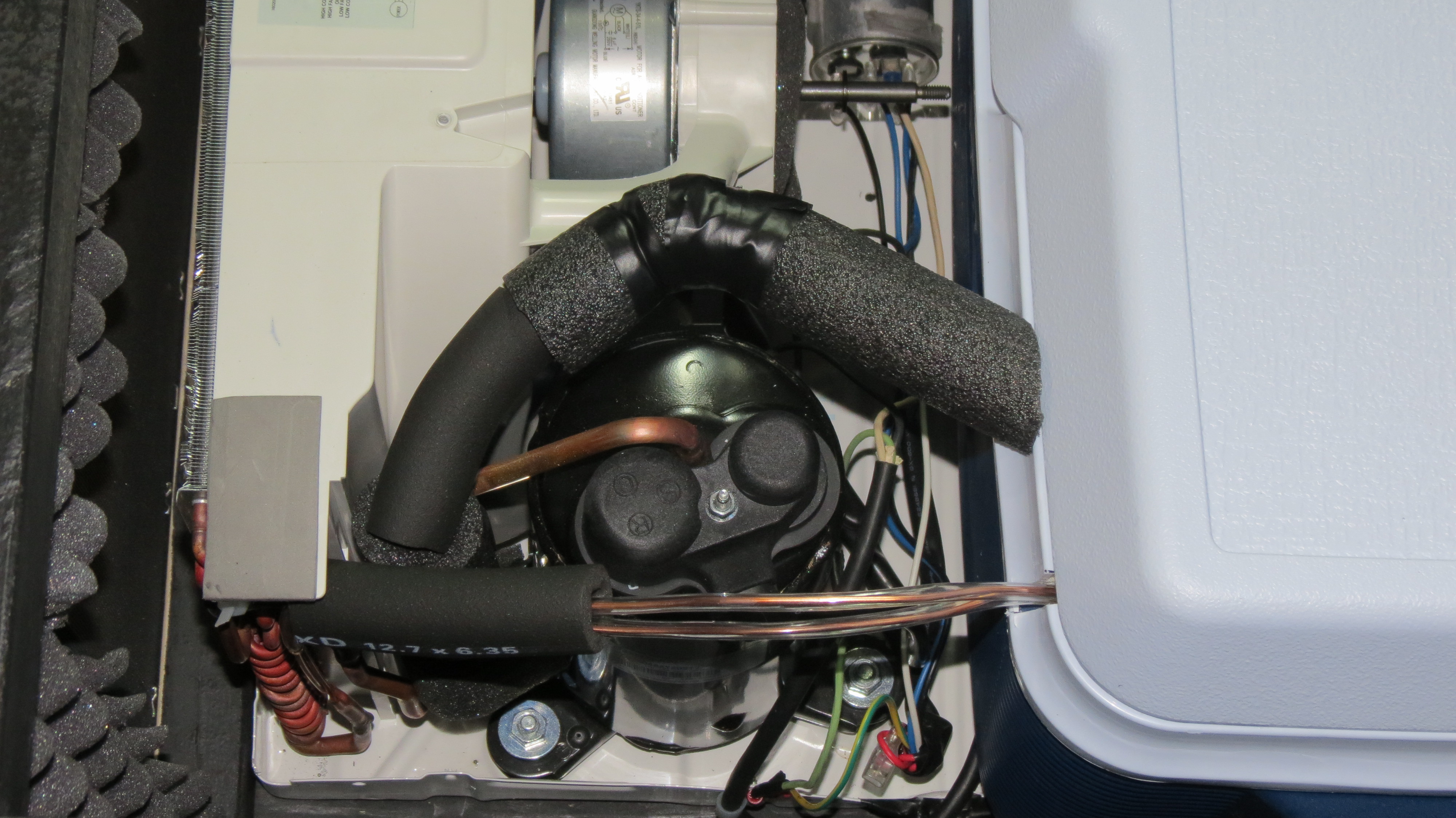
Next bypass the OEM thermostat and remove that. Make sure loose components are secured:
75P7fLh.jpg


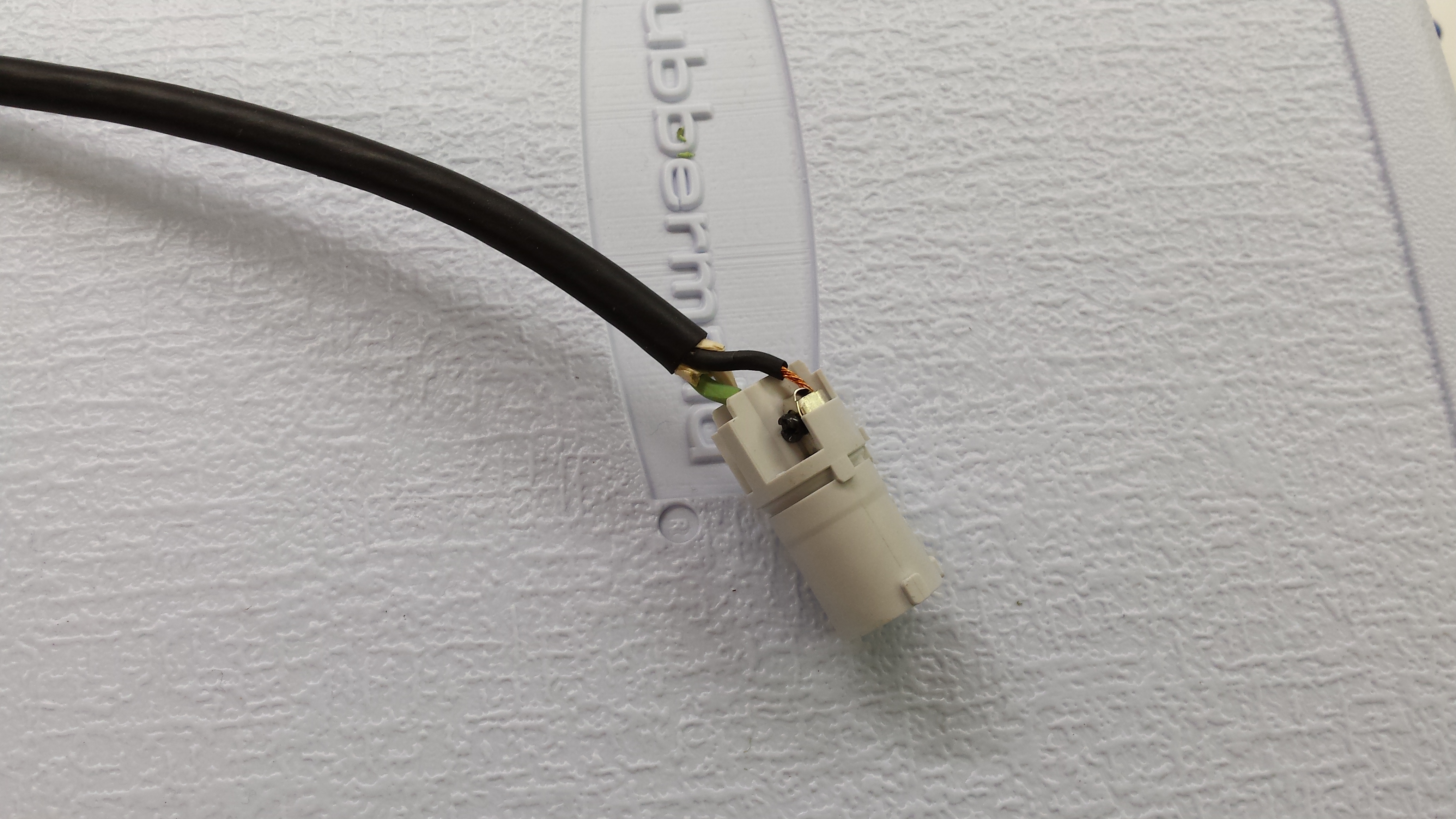
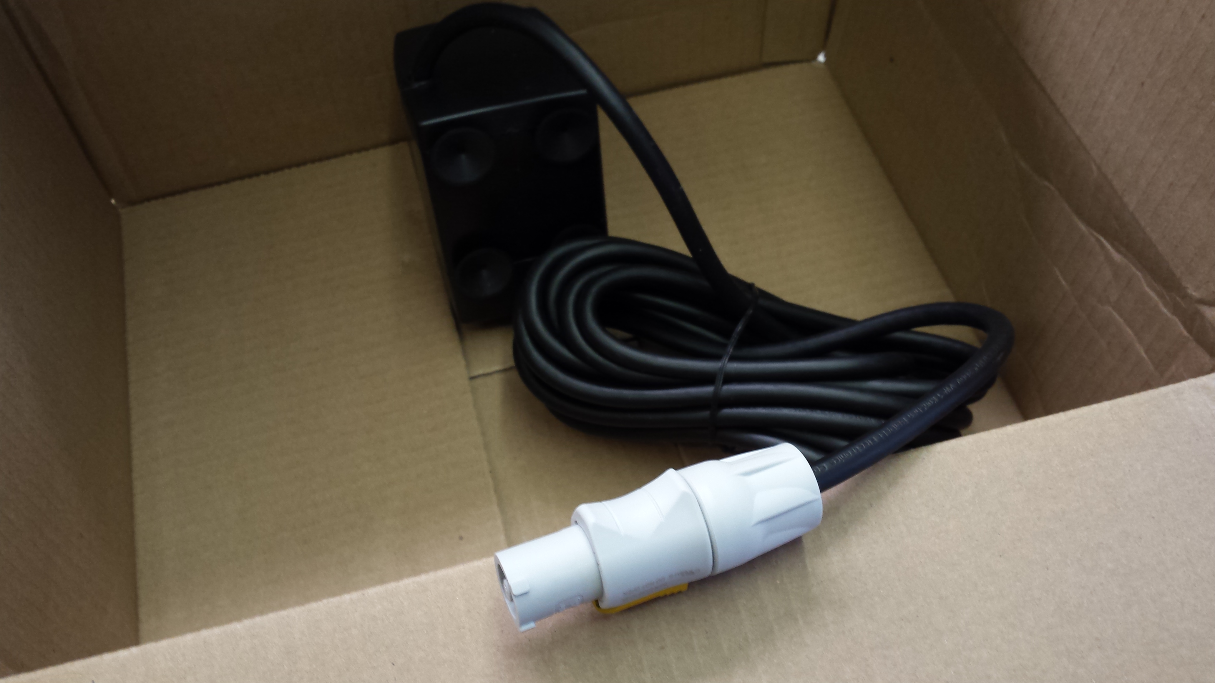
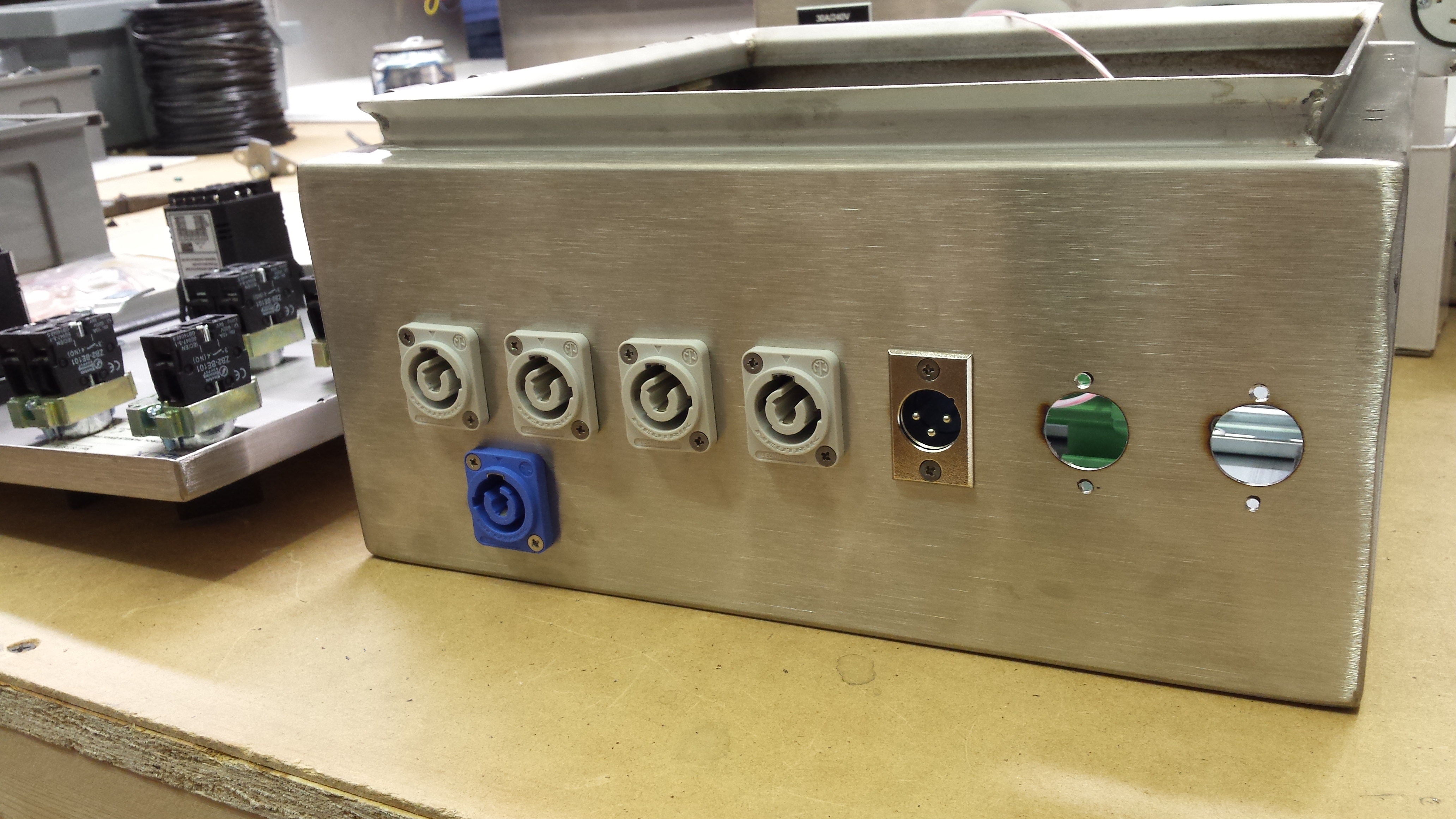
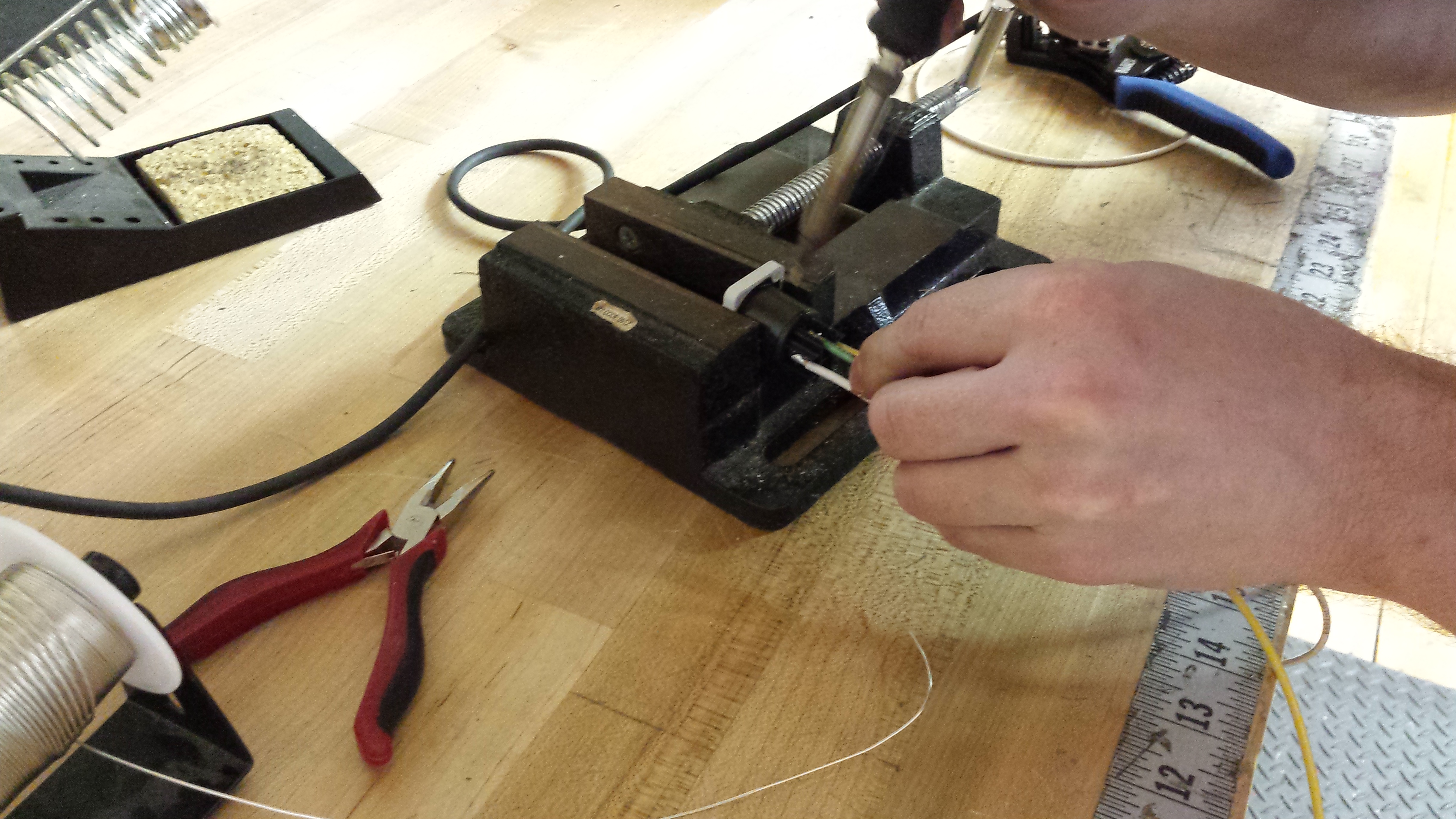
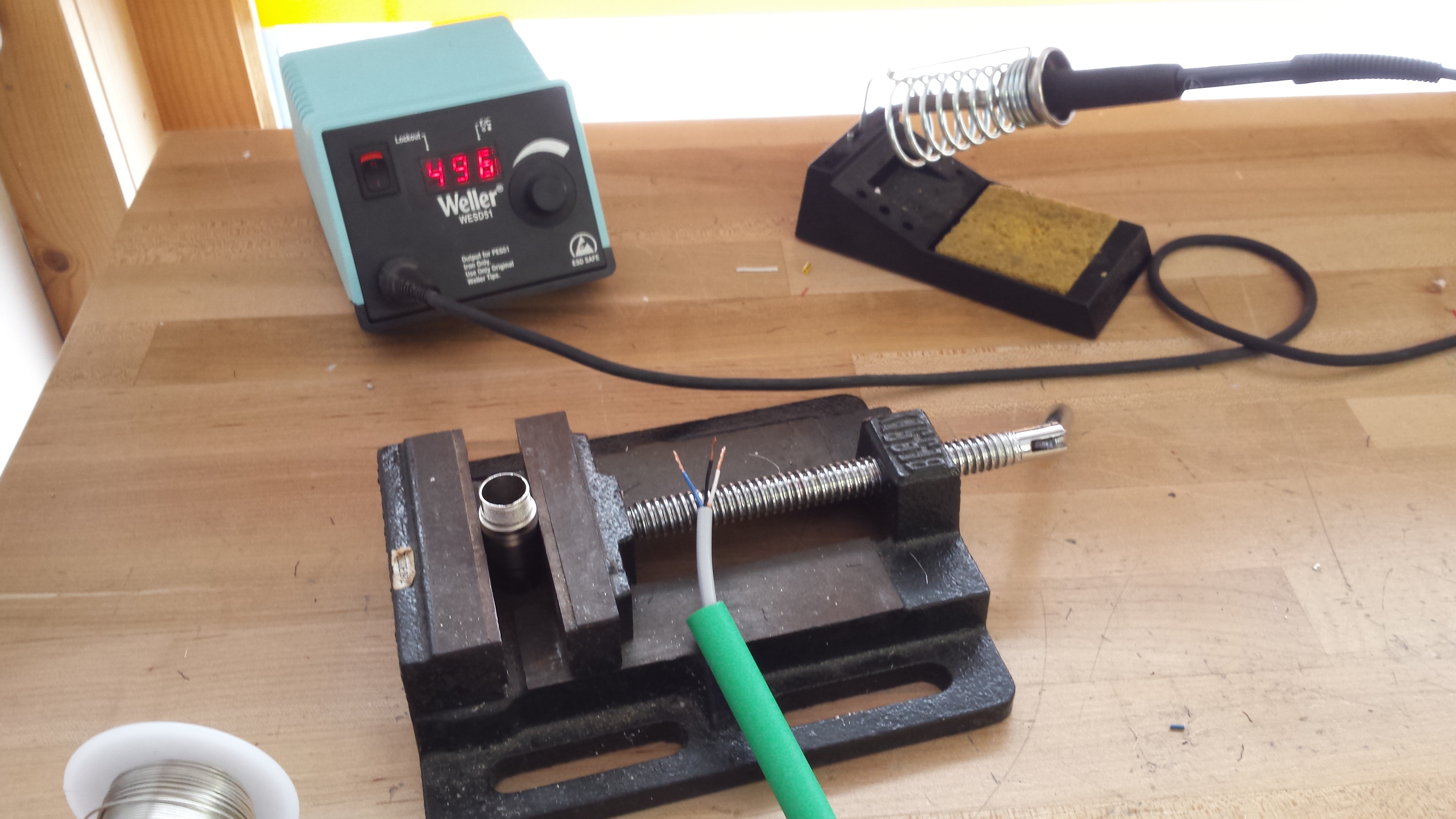
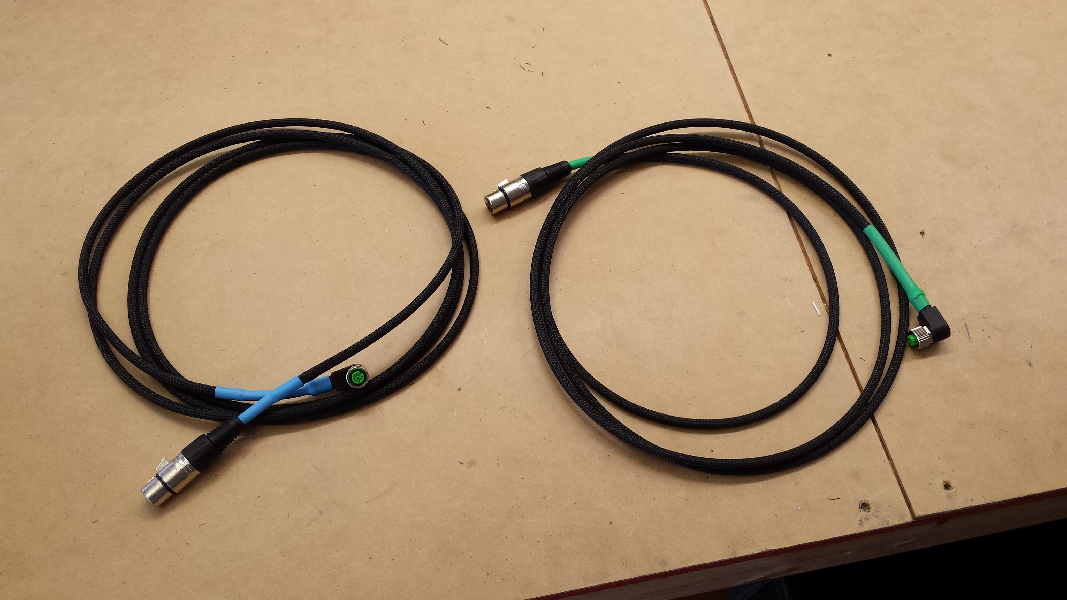
Cut off the GFI power cord that comes with the unit and save that for the control panel, then wire a new power cord for the A/C unit with a twist lock style connector. Also cut the standard connector off the pumps and replace with same twist style connector:
Uarkltb.jpg

YV2QHOn.jpg


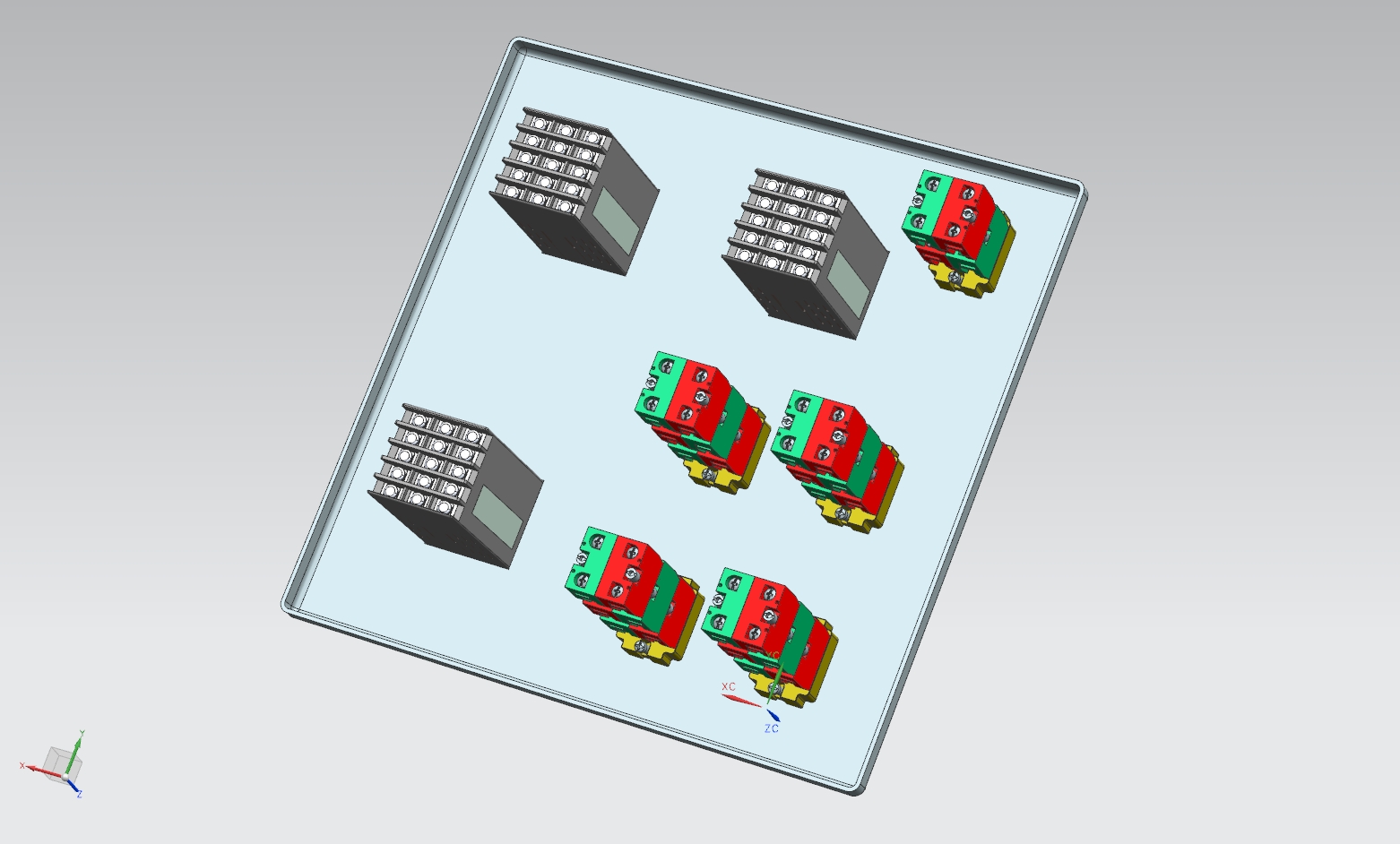
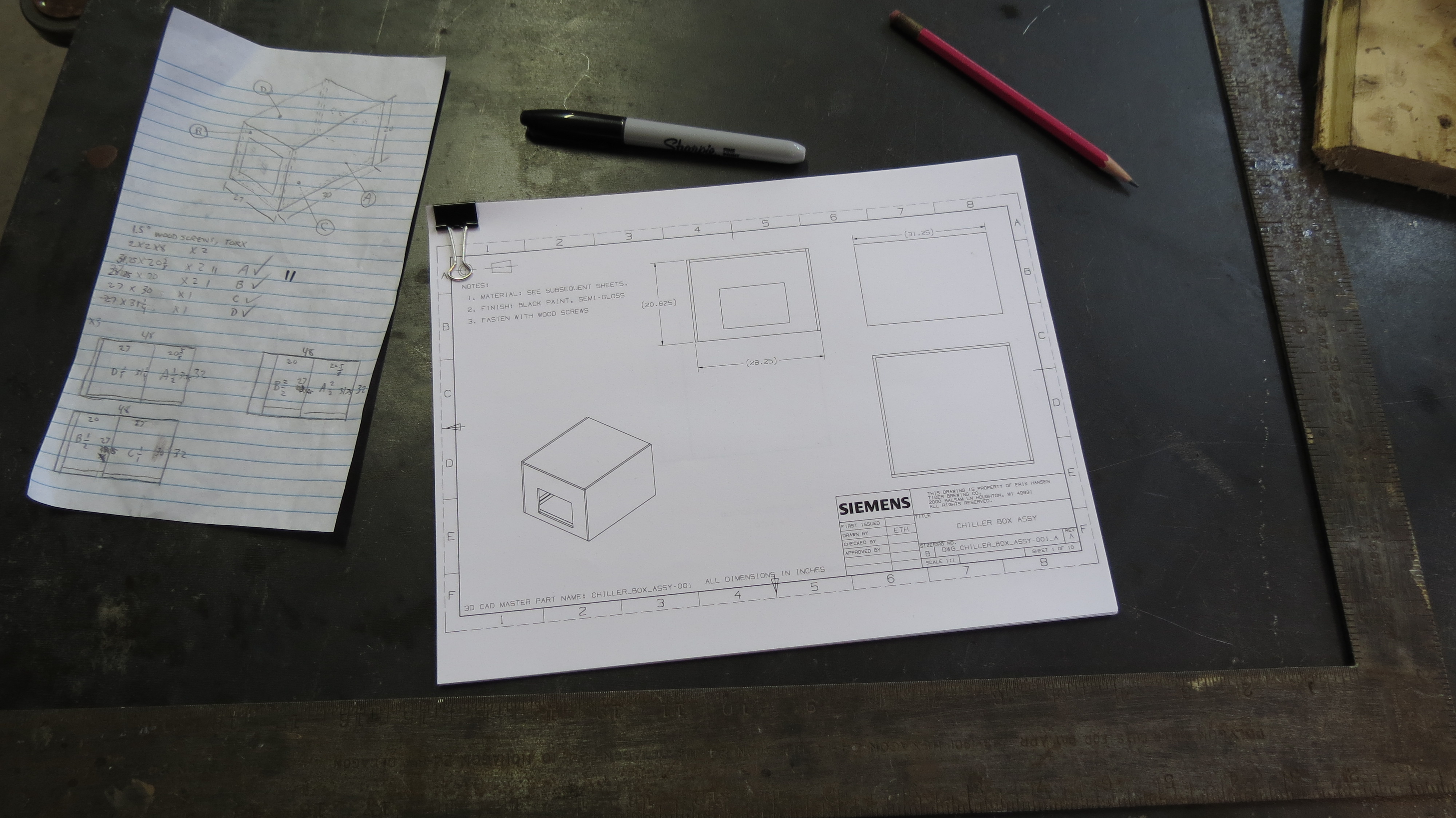
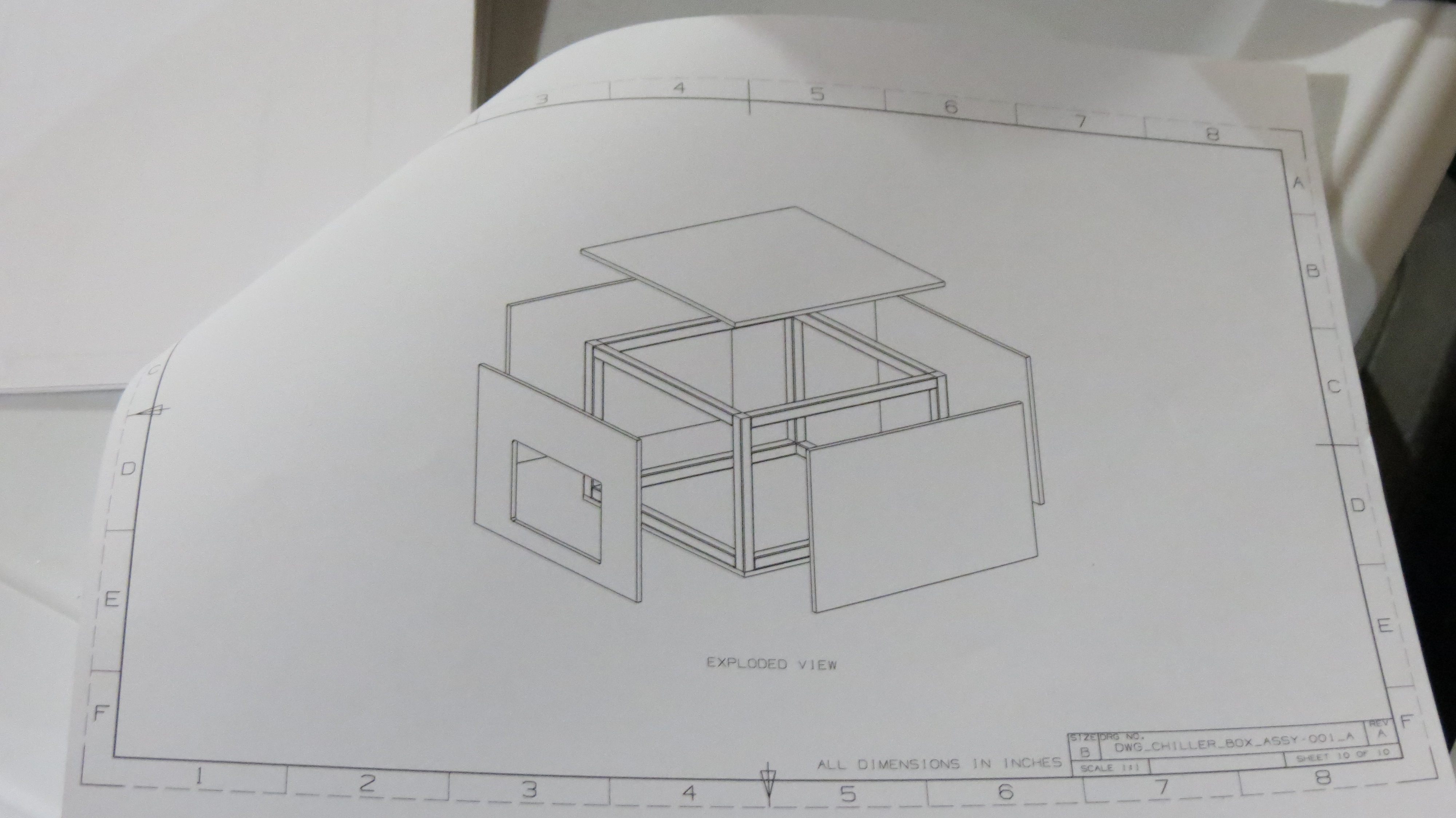
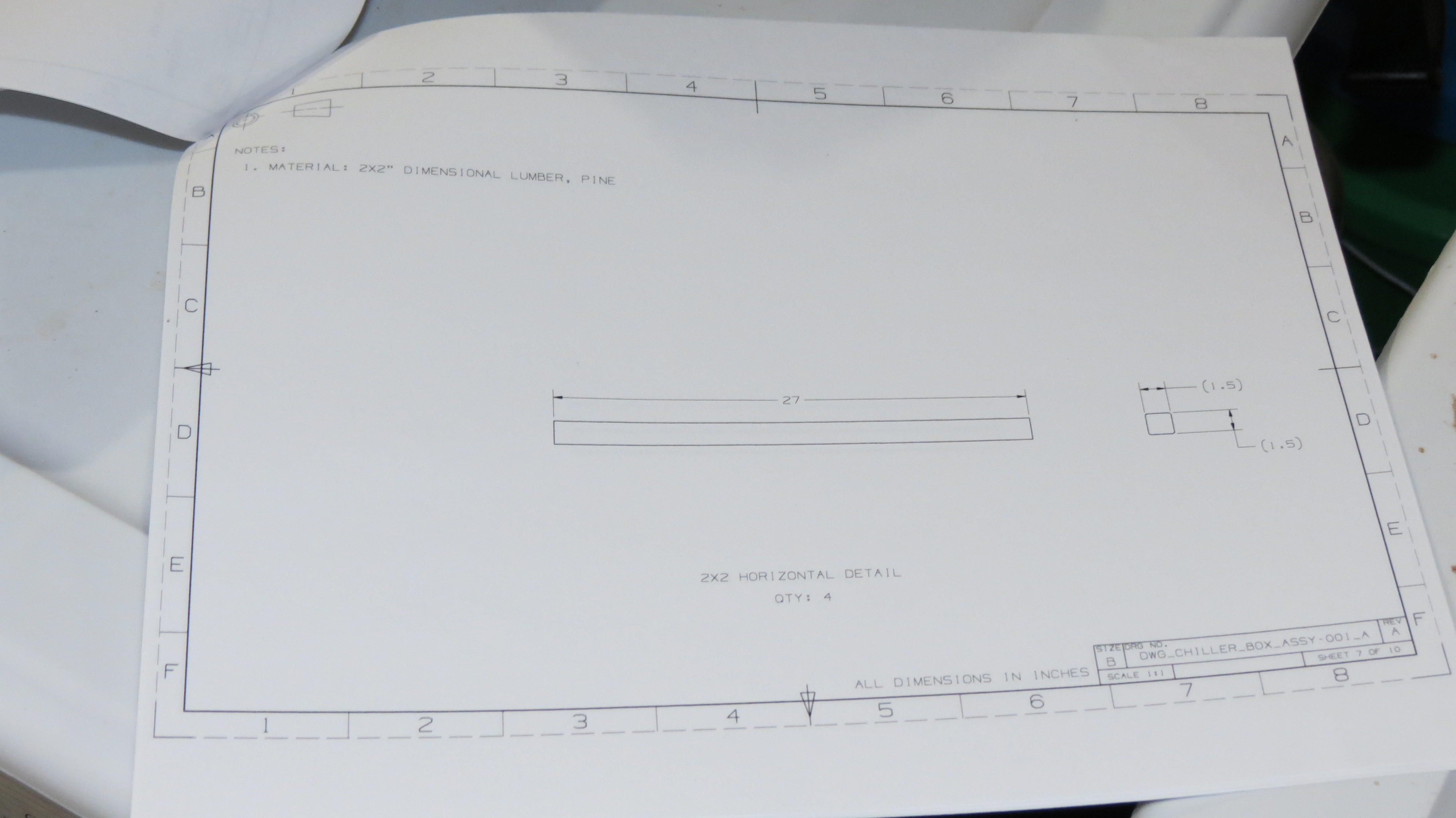
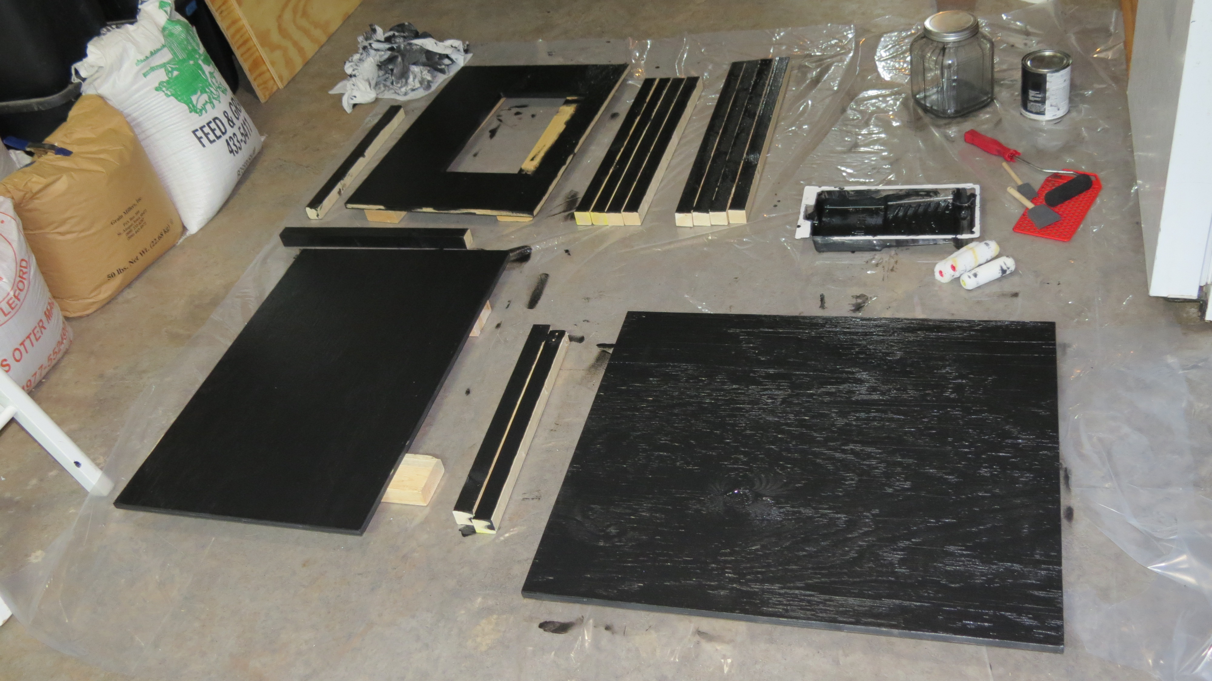
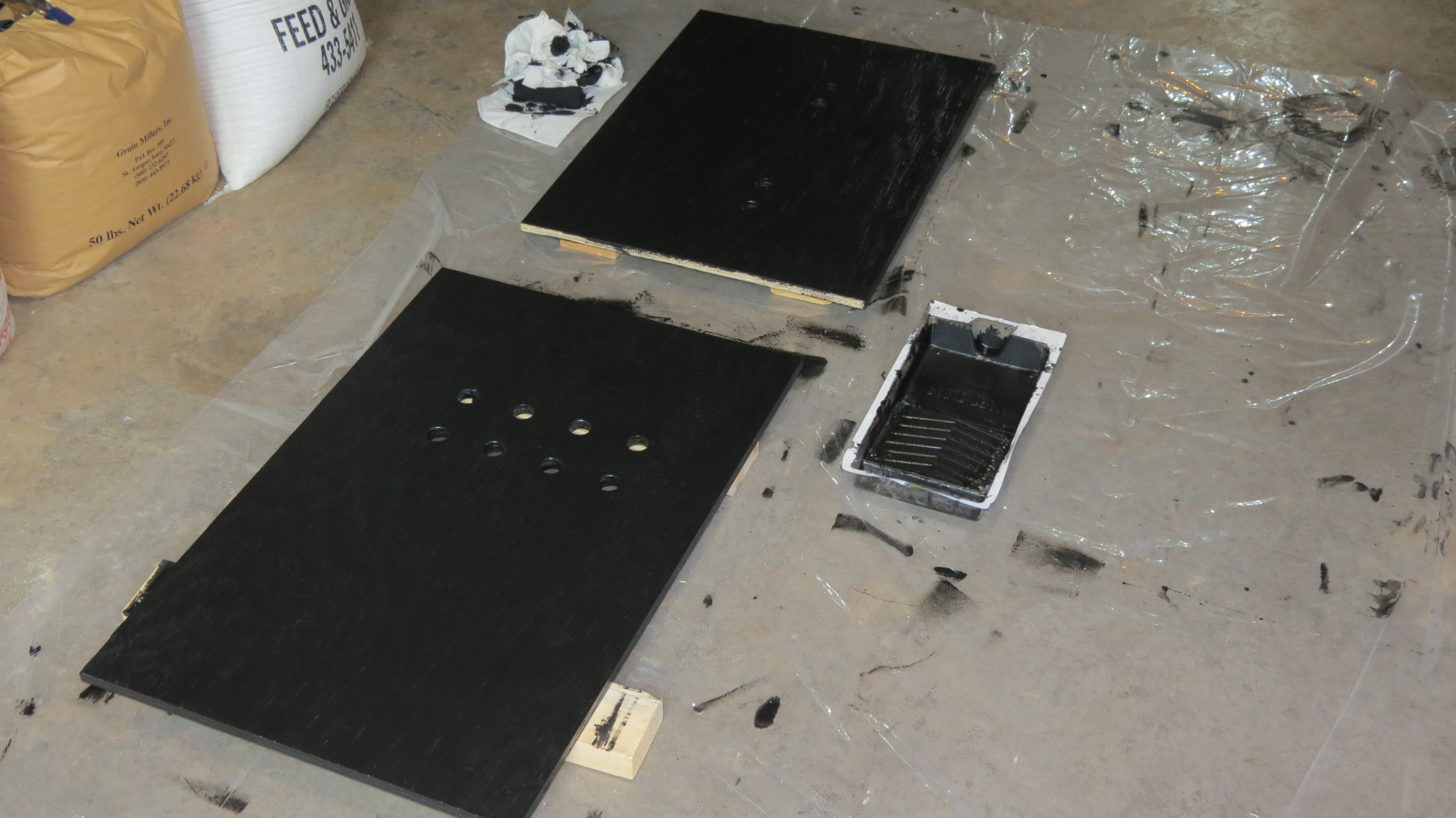
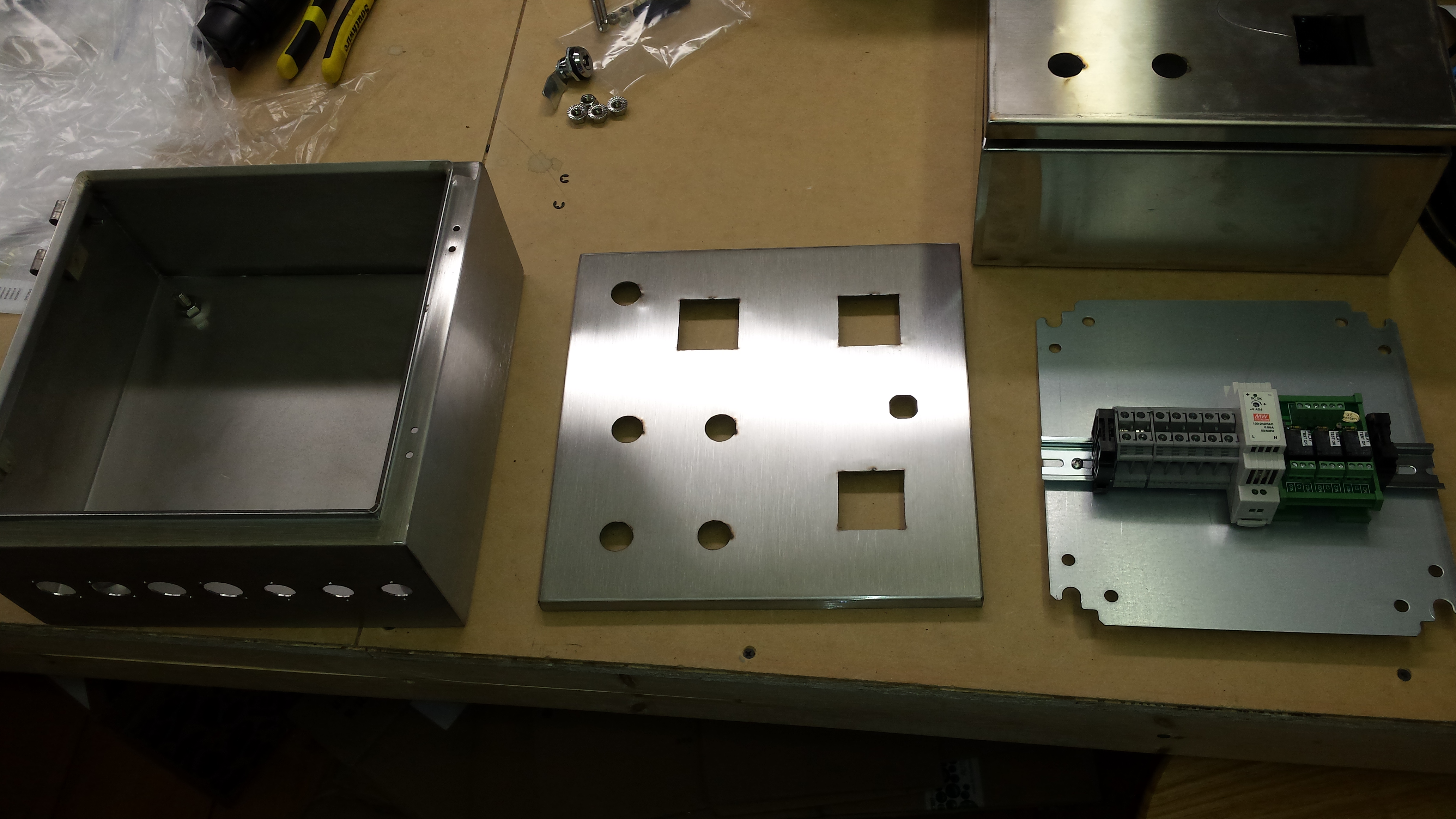
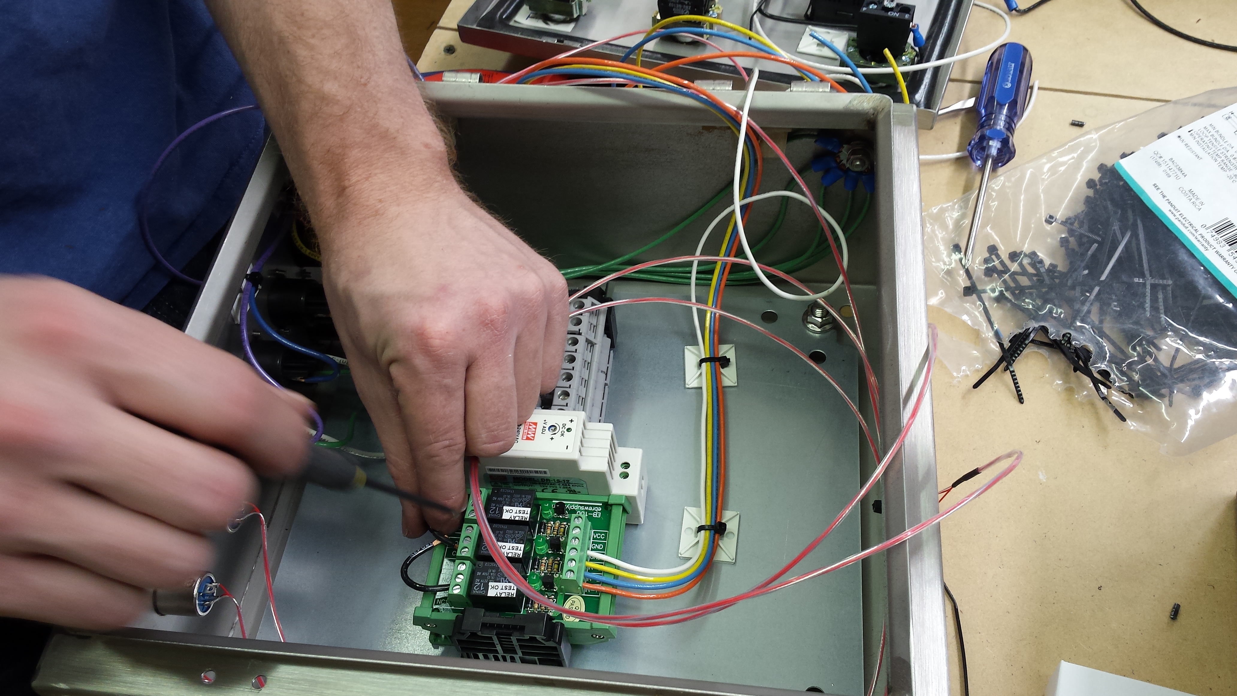
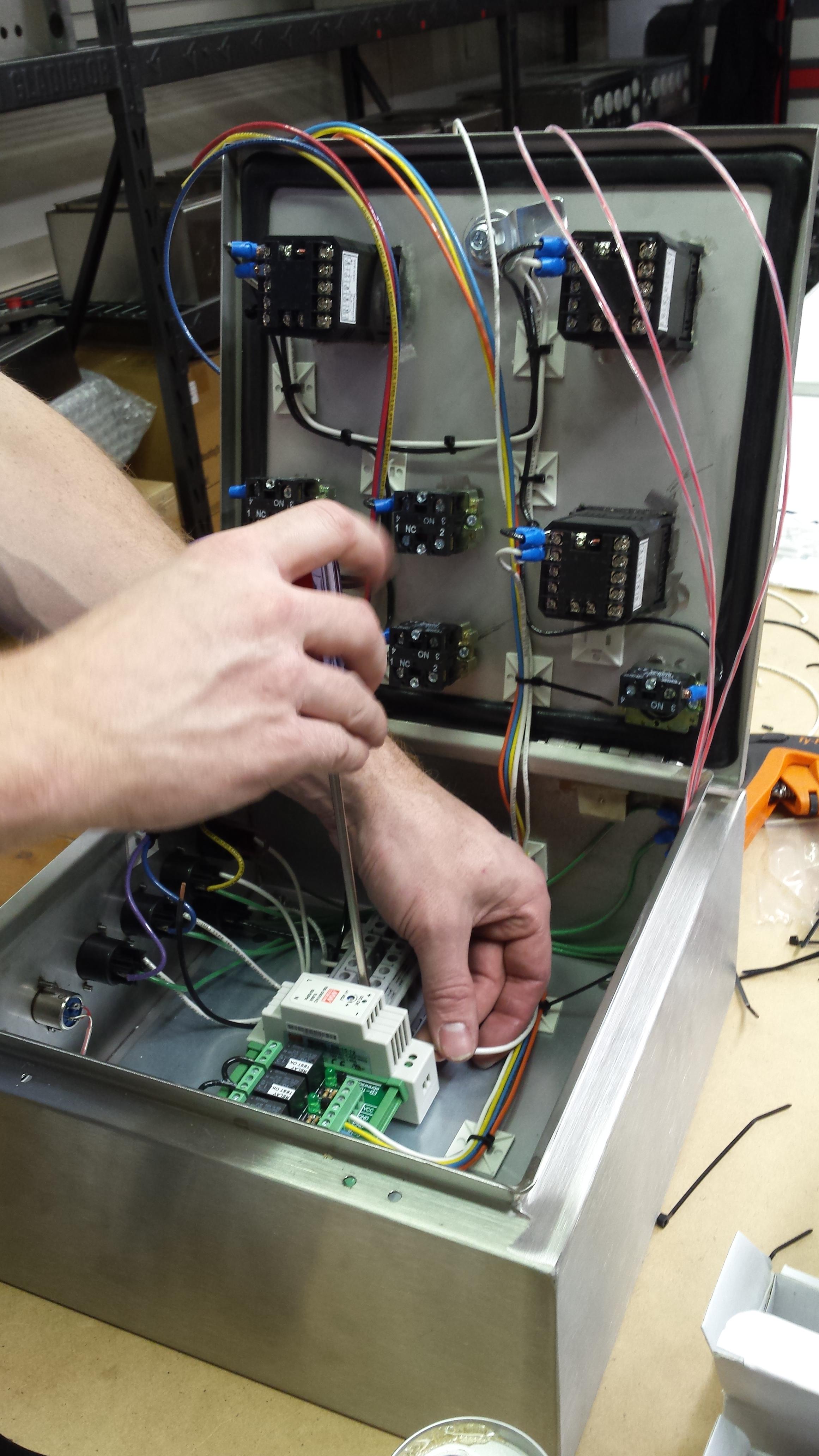
Meanwhile I modeled up a design for a control panel in CAD and sourced the materials through ebrewsupply. Ryan came up with the wiring schematic that would best fit my needs.
VoX7XSe.jpg

gEN9xo4.jpg

3JdncJD.jpg


continued...
 
...continued

I wanted to build a basic box to contain the chiller unit and keep some of the noise down. I started with a model and drawing:
bIVOBwY.jpg

8s34HcU.jpg

7ZJawjI.jpg


Then get to cutting:
XeaA1kw.jpg

0rqe8sE.jpg


Apply a couple coats of paint:
MFdRXv2.jpg

YfAw9xL.jpg


Modify the cooler for the glycol in/outlets and recess the rim for a flush fit of the evaporator lines and wires:
vRWyHzq.jpg

qDTAk5y.jpg

6shtVLh.jpg

pWaKzQs.jpg


I put a screen on the box's front opening for the A/C fan to keep critters out. There are several holes on the side panel to allow air in the box to keep the condenser cooled. I also added acoustic foam on the inside panels to help dampen noise.
68tLLDl.jpg

xeDf8Rc.jpg

OIAnF7O.jpg

792s1lj.jpg


continued...
 
Sounds great... but Photobucket ain't your friend anymore.

[Update]
OK, they show up now with the different image hoster.

Great project, man!
 
Last edited:
The box starts coming together...
5mQIWjM.jpg

NSgiNvJ.jpg

3yd4Q65.jpg


I used leak-stop quick disconnect fittings so that I can pull the box away from the setup without draining all the glycol in the lines. I got the idea from another thread in HBT. Pretty slick.
BZePjZx.jpg


While the chiller box is coming together, I got some new stainless...
qEWHbG0.jpg


Meanwhile I cut and painted some boards to mount the plumbing on the wall:
2nhSgks.jpg

IQiTnjF.jpg


I used pex for the wall mounted plumbing:
ivRCgFw.jpg

FqFsT7J.jpg


Upgraded from camlocks to TC fittings:
2Kv9gtN.jpg

QFBDMyH.jpg


After a thorough cleaning, I attached a heating pad I used to use for my carboys to the conicals. This way I can ramp up the temperature the way I want regardless of ambient temps. I use the PID controller box I built for my old carboy configuration.
v4hhADf.jpg


continued...
 
You have a wire diagram of the chiller panel? Been thinking about doing that. I already use a chiller for my tap lines. Been nice to extend that to conical chiller.
 
...continued


Neoprene jacket is on. The power cord and thermocouple for the heating pad come out of the opening for the legs in the jacket. The port you're seeing is for the cooling coil.
dbGcX0v.jpg


Determining hose length from the conical to the hard lines. I used leak-stop quick disconnects again here. For this stretch of plumbing I used automotive grade insulated silicone tubing - another idea I got from an HBT thread here.
nIZAuCV.jpg

975kiXd.jpg


CIP spray ball from brewershardware.com and 3" TC piece I put together for pressurizing the fermentor with CO2 for crashing and transfers that also fits on the top TC ferrule. I'm told that SS Brewtech now offers the 3" TC x 1/2" NPT with a PRV, which I would've gotten had they been available at the time. I monitor the pressure on the regulator feeding the fermentor carefully to make sure I don't exceed the recommended 2psi limit, but a PRV would be nice insurance to avoid damaging an expensive hunk of stainless steel.
j5QkOvu.jpg


Water testing the fermentors and CIP spray ball:
nr0E87x.jpg

d82qLw6.jpg


Cleaning more fittings:
FDmN5ZL.jpg


First fermentor assembled and hooked up to the glycol plumbing. Progress on the box is stagnant at this point until the control panel is finished:
Hsia0co.jpg

ylI2lyb.jpg


Continued...
 
...continued


Fun day at the ebrewsupply shop. He's really set up well and knows his stuff, so this went relatively easily. I supplied the CAD generated .dxf files and he got his CNC to do the rest.
K1VTrrW.jpg


He then printed my text layout on the panel cover with his laser etcher, and afterward I started populating components. Starting to look like something...
PxaymD1.jpg


Adding more hardware:
4TtaoXp.jpg


Soldering receptacles:
M5LxES0.jpg


Then began the wiring. Ryan is a hundred times faster at this than I, and the schematic was more or less in his head anyway, so best to let let the wizard work his magic:
2E14nkg.jpg

P5y1xfu.jpg

HArpzmU.jpg


Before I could finish my beer, the panel was complete:
qxvO1Bd.jpg

P5ASzgJ.jpg


Then I cut and painted some 2x4 to mount the panel to the wall:
gXXE8Zf.jpg

E4wJYDs.jpg


With the control panel finished and mounted, I could feed the cables through the last wall of the box and get that finalized. I used trimmed pieces of pipe insulation to secure the wire through the holes that the connectors had to fit through. If I would've expanded my budget, I would've done this differently and installed a small connector panel on the side of the box where I could plug/unplug each cable from the box itself. It's not too late to upgrade in the future...
KJKA59K.jpg


continued...
 
...continued


I then assembled the fermentor RTD cables:
izxlkCt.jpg

GDFyY5X.jpg

QhsZW4t.jpg

9vGW7ir.jpg


Finishing the glycol system:
KKtSJYk.jpg

ghaCahk.jpg


Time to integrate everything:
2ARHKfP.jpg

JLyZv3u.jpg


I chose a 34% Propylene Glycol / distilled water ratio based on the temperature I needed. Handy guide found here.
FSkn5YP.jpg


Testing the plumbing for leaks and the glycol pumps controls for functionality:
29JIOu4.jpg

9O9IVl1.jpg


Glycol RTD added (I've since replaced this with the same IP67 rated RTDs used for the conicals, though I don't have a pic):
pm7WWn7.jpg


A shot of the chiller box with the lid off. I wrote the ratio and amounts of water and glycol on the cooler lid for future reference:
2OzNpnh.jpg


continued...
 
More preliminary testing of the panel. The glycol PID and parameters shown here were temporary; currently installed is the Auber SWA-2441, which is the only 1/16 DIN PID that I've found that has anti-short cycle delay for compressors.
TFaz9Ej.jpg


Hooking up the second conical put together in the same way (including embedded heating pad) as the first:
f4G2XIp.jpg


Starting to wrap up the build:
k7iiBhA.jpg

3vq6TBF.jpg

QvmtIq6.jpg

CuXqHFT.jpg


Some more cleaning and passivation:
dxG8Ty2.jpg


And a new stainless work top for lab work etc.
S2OR72C.jpg

smHB0aR.jpg


Everything is set and ready, so the first couple batches of beer are brewed and fermenting:
hcKybwj.jpg


Getting ready to dump the trub:
U7tckR0.jpg


Come time to cold crash and lager, using my CO2 adapter to maintain positive pressure in the fermentor:
5XkMVyU.jpg


continued...
 
...continued


Kegging:
EfxG8bi.jpg


The mess left behind after fermentation. Nothing some 150F PBW solution and a CIP spray ball can't take care of.
t5VhnKn.jpg

KbdgqEj.jpg


Fruits of my labor: a low oxygen German Helles. Squeaky clean and delicious!
mTqahoW.jpg


Cheers!
 
Nice find on the auber with a compressor delay. Nice to match the brew panel

Awesome work, will be stealing some of your ideas once I can find the time
 
Thank you very much. I am trying to mimic your setup. What fittings were used to go through the cooler wall for the glycol lines?
 
Great looking set-up! Where did you source your heating pads?
Thanks, Brian.
Thanks!

You used to be able to get them via Midwest Supplies or Northern Brewer, but it looks like they don't sell those anymore. If you search for "fermentor heating pads" or something similar, you might find something that works.
 
Back
Top