Cregar
Well-Known Member
Bump

Cregar said:Bump
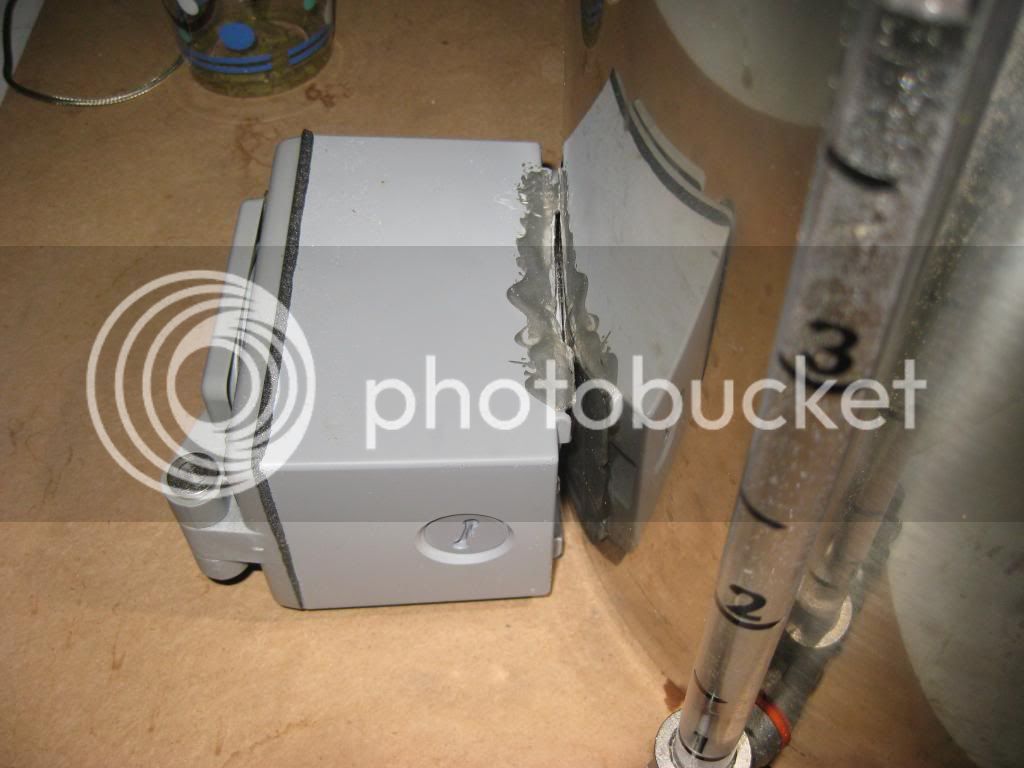
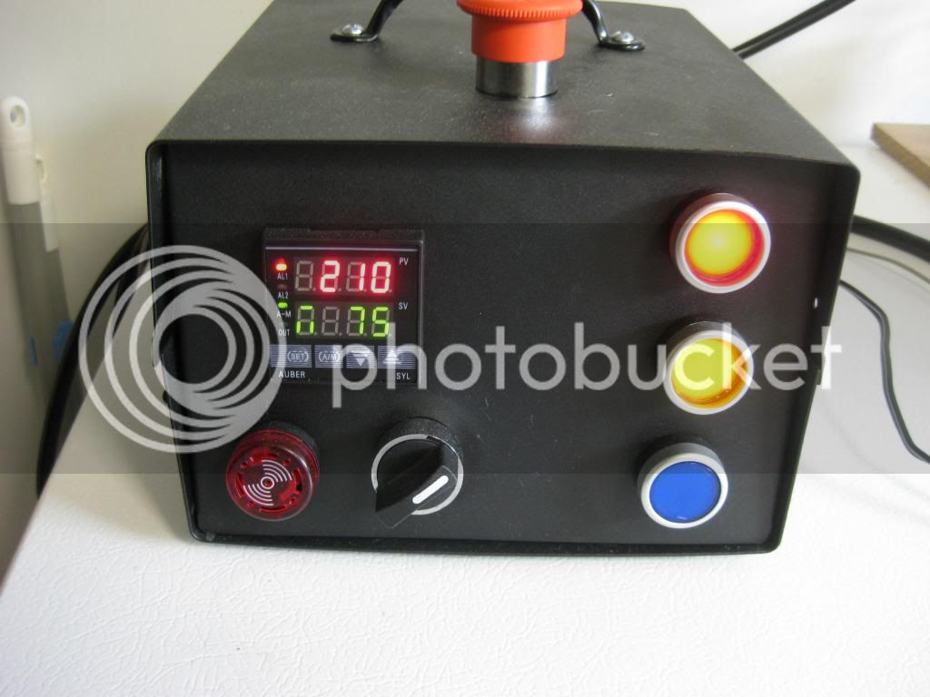
I see machine screws used to mount the contactor and bus bar to the Auber box. Any issue with using JB Weld to mount them to the inside of a structural foam water resistant tool box?
I don't think so - the stc can't react fast enough to make the temp adjustments needed.
jeffmeh said:It would be a pain in the neck if you ever had to replace a component, or move one temporariliy to get into a tight space. Why not use a sheet of plastic or metal as a backplate for mounting the componenets?


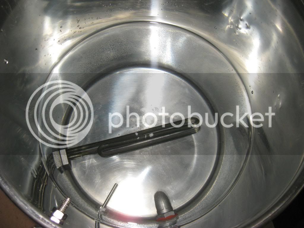
 It was traumatic.
 ^I had a lot of trouble with mine too. Turns out I had a gasket in the magnetic drive.
Try opening yours up and pull the magnet. Clean out the cylinder and check for any debris. Be careful when putting it back together - the screws are very easy to cross thread.
BoxBrewer said:Cool thanks... I have had trouble with it since day one, honestly. It can't prime itself, it seems. Even if I put the pump lower than my kettle, the liquid won't flow.


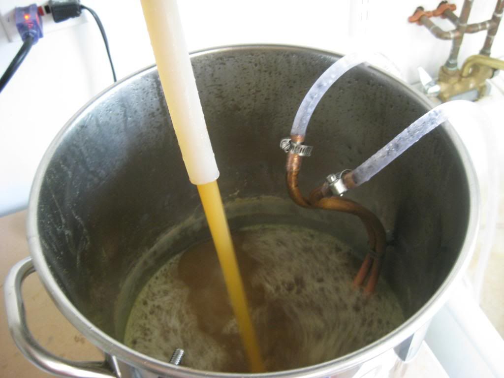
Do you guys think something is wrong with my pump?
Do you guys think something is wrong with my pump?
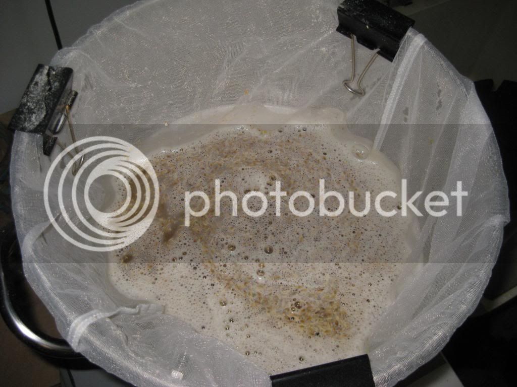
Efficiency is probably 90% crush dependent.
biab loses points in the sparging area, but gains points in how fine you can go.
If you're relying on the LHBS mill, double crush. If you have your own mill, tighten that baby up.
jrb03,
I see that you have been a member here for several years and I'm honored to be able to answer your first post.
I spent a few hours this morning drawing a diagram that should fit your needs.
I hope this is of some help to you.
Wishing you the best.
P-J
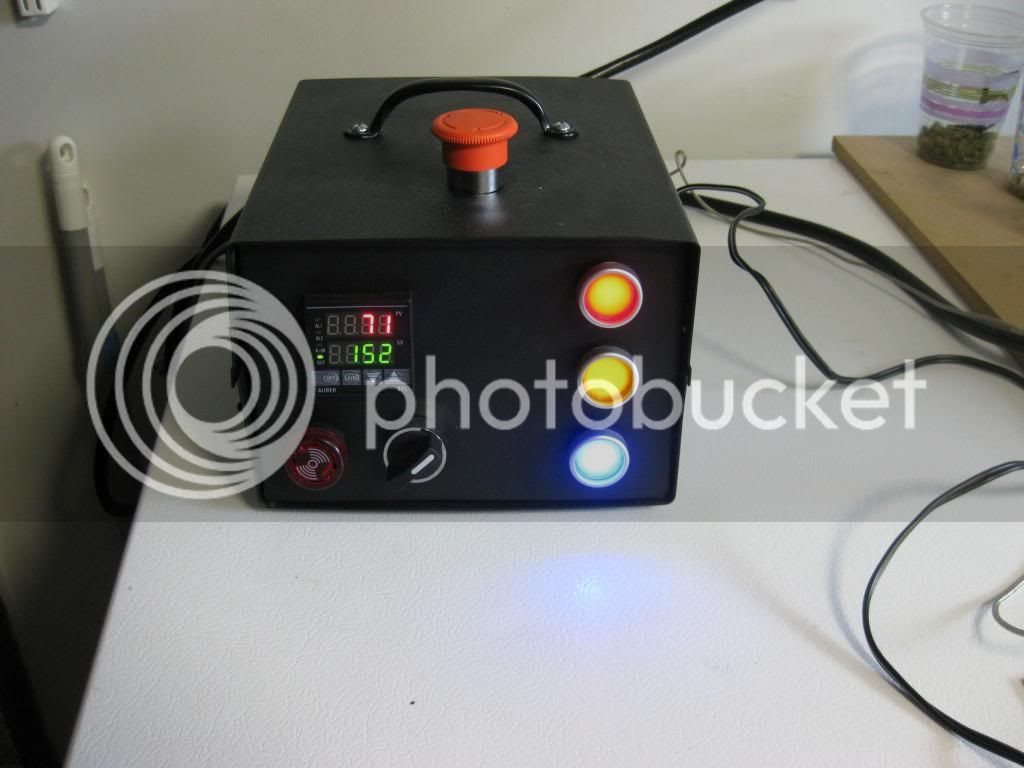
It's been awhile and I don't have access to my rig right now. There should be only 2 connections to the e-stop, a ground and a hot that is fused and resistored before the e-stop connection. They should be wired in the normally open position. When you push the e-stop and close the loop, it sends a small electric current through the ground wire which trips your gfci and de-energizes the controller. Hope this helps.
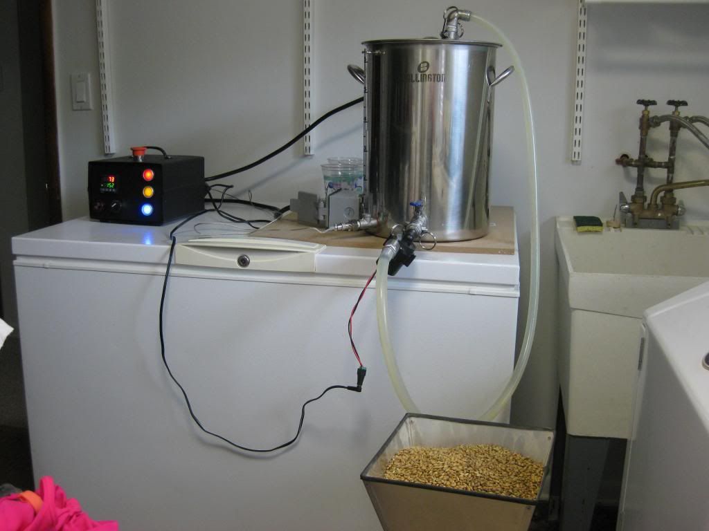
If I have missed anyone's questions I apologize, please repost. I have been crazy busy traveling for work and life in general. Haven't brewed or been on the forums much the last few months. It's great to see more people are building this rig, let's see what your brewing!
Ok, so that helps with the idea on tripping the GFCI. My plan was to use the uh oh button on first power line into my board. Then rely on the GFCI to do it's job since that is why it is supposedly in my kitchen in first place. But I get the redundancy idea.
Next...what exactly is the alarm switch doing? Meaning, why the two way NO/NC switch and not just a on off? What I am wondering is: does the switch reset the alarm? (I can't see how), does the switch turn it off and reset the aubrines some how? (prolly need to read those instructions),
....or do you turn it once to kill alarm, reset the controller and then turn switch back??
Which diagram? Which post number?Has anyone added a timer to the original wiring diagram? Seems like it would be nice to have.
I've added the Auber Instruments Timer JSL-71A to the diagram. I hope that is the one you were looking to incorporate in your build.That would be great P-J; Post #2, original diagram.
Thanks,
Ben

I've added the Auber Instruments Timer JSL-71A to the diagram. I hope that is the one you were looking to incorporate in your build.
And - as always - Click on the image to see (and save) a full scale diagram printable on Tabloid paper (11" x 17")
Wishing you the best.
P-J
Ben,Perfect! I really appreciate that P-J. Appears the timer won't go as deep into the box as the PID so I might be able to cram all that into the box referenced in this build without having to step up to a larger box.
I've added the Auber Instruments Timer JSL-71A to the diagram. I hope that is the one you were looking to incorporate in your build.
And - as always - Click on the image to see (and save) a full scale diagram printable on Tabloid paper (11" x 17")
Wishing you the best.
P-J
You can use the same buzzer. You would need to wire terminals 6, 7 & 8 in a similar manner as the wiring on the PID terminals 1, 13 & 14.Easy question (i hope!) In this diagram, if I wanted the buzzer to go off when the timer counted down to zero, would I simply add a wire from location 7 on the timer to location 22 on switch #4? I would I need a seperate buzzer? Thanks
You can use the same buzzer. You would need to wire terminals 6, 7 & 8 in a similar manner as the wiring on the PID terminals 1, 13 & 14.

Enter your email address to join:
