Help with wiring a 120v 1500w element control pumps with 2 pumps

Homebrew Talk - Beer, Wine, Mead, & Cider Brewing Discussion Forum

Help Support Homebrew Talk - Beer, Wine, Mead, & Cider Brewing Discussion Forum:

This site may earn a commission from merchant affiliate links, including eBay, Amazon, and others.

fusa

Senior Member
Joined
Feb 18, 2010
Messages
392
Reaction score
55
Location
Blacksburg
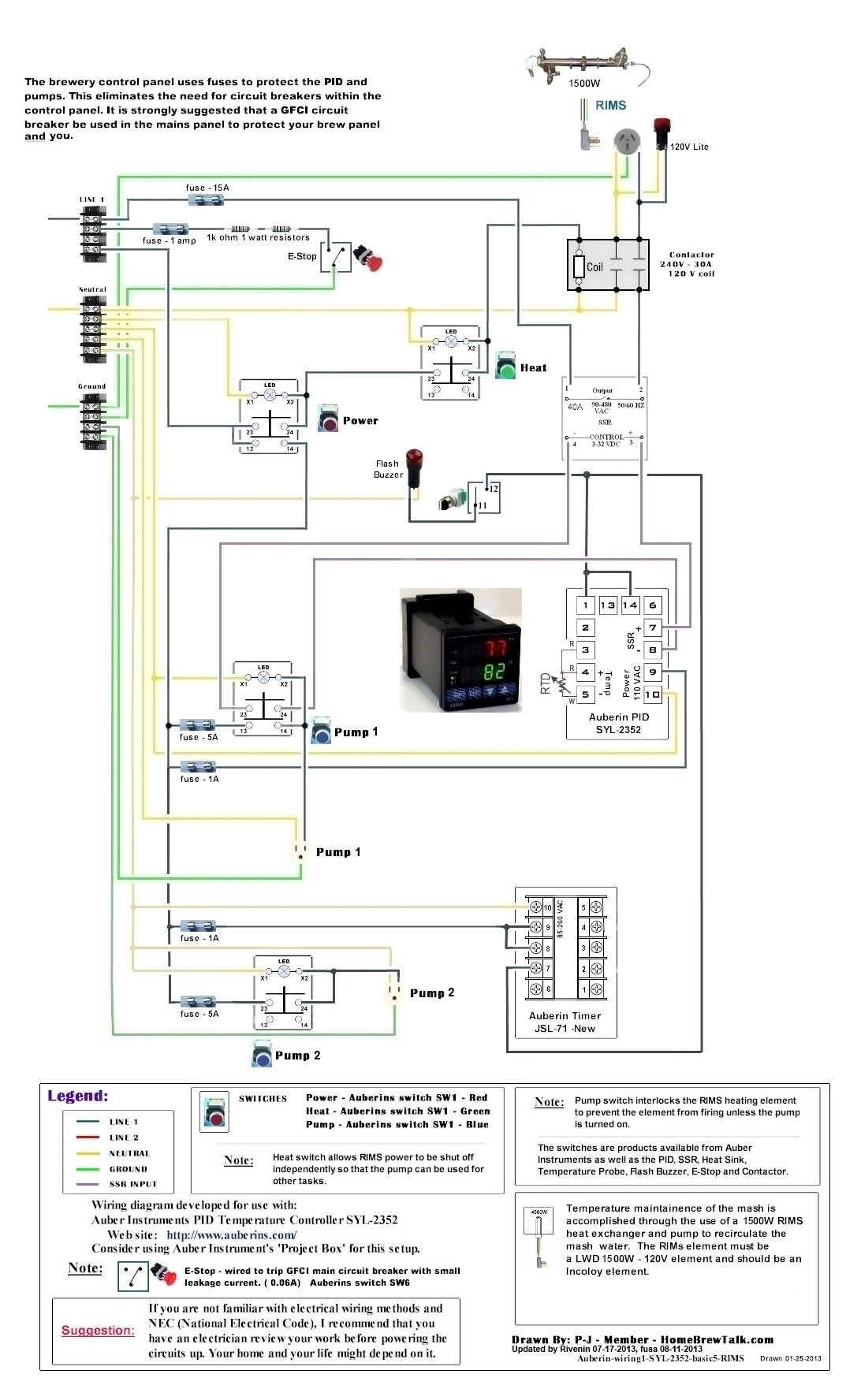
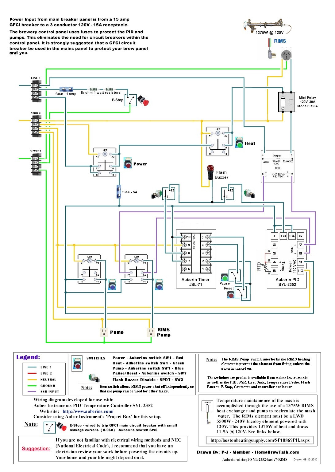
Based off of this diagram

Auberin-wiring1-SYL-2352-basic5-RIMS.jpg


I would like to create a control box for my rims tube element and 2 pumps.

I am confused about how to add the 2nd pump and control switch for the second pump.

So far my parts list is:

2 x Terminal Strips (4 pole)
1 x Terminal Strips (5 pole)
1 x jumper
1 x External Mount Heat Sink
1 x 25A SSR
1 x Contactor, 2 pole, 30A, 120V Coil
1 x Emergency Stop Switch
4 x Illuminated Maintained Pushbutton Switch, 2 NO, 22mm. 120/240V 2 blue, 1 red 1 green
1 x 1/16 DIN PID Temperature Controller (SSR control output) Model: SYL-2352
1 x LED Indicator, 22 mm, 120V
1 x Chassis-Type 4-Position Fuse Block
1 x 1 amp fast acting fuse (4 pack)
1 x 5 amp fast acting fuse (4 pack)
1 x Bussmann BP/AGC-15 15 Amp Fast Acting Glass Tube Fuse
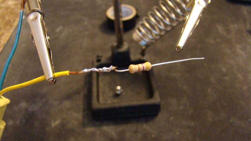
1 x 1k-ohm 1W 5% Metal-Oxide Film Resistor (2-Pack)

1 x 12x12x8 300x300x200 ENCLOSURE WITH BACK PLATE INDOOR/OUTDOOR

I still need to decide on the box to use and the outlets. Which 1k ohm 1watt resistors should I use?
 
Last edited by a moderator:
So all you want to do is add one more pump and a switch to control said pump, right? i'm just making sure before i jump into switching that diagram around as it takes a bit :) :mug:
 
Yes thats right. I'm mostly confused where the lines connect at the switch for the 2nd pump.
 
okay, so after looking at this... it's showing that it only wants the element to run while the pump is going.

Do you just want a single manual pump with no interaction with the element? sorry, i just caught that, i'm at work at the same time i was reading that :) lol
 
Yes the element would be independent of pump #2. Thanks for looking at this for me.
 
No problem! my MS paint skills are that of a professional :mug: haha, hopefully this helps though!

Auberin-wiring1-SYL-2352-basic5-RIMS_zps593b70f7.jpg
 
Also, the max wattage you'll in reality get away with on this is 1500w.
if you use 2000w on a 20amp circuit and 2 pumps, you'll overdraw the system. (running 1 pump would be fine though)
Just FYI :) if you want to use a 2000w element, you'd need to run it off of a seperate circuit.
 
Fuse holder (this has 4 holders, which will make things easy, but any should work just fine.)
http://www.radioshack.com/product/index.jsp?productId=2062258

As for the resistors, those will work fine, they have a few different 1k ohm resistors, make sure you get the 1watt ones.

Best way to connect them would be soldering them and putting shrink wrap over them. like this.

equinox-albums-racing-seats-airbag-fix-picture7406-here-resistor-being-soldered-resistor-needed-4-7-ohm-1-2-watt-resistor-radio-shack-didnt-have-so-i-ordered-online-you-will-need-two-one-each-seat.jpg


Let me know if you have any more questions! :mug:
 
I have updated the drawing. I added a timer and alarm. Let me know if there are any problems with the changes.

kgnul85.jpg
 
fusa,

I took the liberty of making a diagram for you that might fit your needs:

As always:
Click on the image to see and save a fullscale diagram that is printable on Tabloid paper (11" x 17").


I hope this helps you.

P-J

Note: I revised the diagram to show the JSL-71A timer.
 
After looking over the diagram, I noticed that my JSL-71A timer is the new version. I updated the drawing below.

IjWFAMq.jpg


One question about the timer. The PDF shows line going to 9 and neutral going to 10. Does it matter which one neutral and line are connected to? I was referring back to https://www.homebrewtalk.com/f170/wiring-auber-jsl-71-reset-413105/#post5284118 to update the drawing for new version of the timer.
 
After looking over the diagram, I noticed that my JSL-71A timer is the new version. I updated the drawing below.

One question about the timer. The PDF shows line going to 9 and neutral going to 10. Does it matter which one neutral and line are connected to? I was referring back to https://www.homebrewtalk.com/f170/wiring-auber-jsl-71-reset-413105/#post5284118 to update the drawing for new version of the timer.
The neutral & line placement for AC power-in does not matter.

Good catch on the JSL-71 new version and good job fixing the layout.
 
Thanks again for all your help. It has really made it much easier to understand.
 
This is exactly what I've been looking for!! Thanks to all of your for putting it together!

If I buy the parts list above, will I have everything I need to assemble it?

(sorry for reviving such an old thread...)

Thanks in advance for your advice!! :mug:
 
If I remember correct yes. I THINK the following is the final draft of the wiring. It should show everything that I bought for the panel. I never used the jumpers, didn't fit the terminal strips so just used wire to make them. The panel you can get from Auber Instruments now, or other sources. I also used BobbyM's rims tube and heater element from brewhardware.com.
I can't offer any help with wiring it, the only training I have is help from P-J icebob and a few others here.


panel_final.jpg
 

Latest posts

Back
Top