Show me your RIMS set up

Homebrew Talk - Beer, Wine, Mead, & Cider Brewing Discussion Forum

Help Support Homebrew Talk - Beer, Wine, Mead, & Cider Brewing Discussion Forum:

This site may earn a commission from merchant affiliate links, including eBay, Amazon, and others.

Flaviking

Well-Known Member
Joined
Apr 3, 2012
Messages
239
Reaction score
10
Location
Pompano Beach
Hey guys, Just got my RIMS tube in the mail yesterday, looking to see some of everyone's set up to help me decide on where and how to hook it up. Looking forward to seeing some great ideas!

Thanks!
 
The picture may not be very clear...I have my 18" RIMS tube attached to my Top Tier brewstand. You'll see the bottom of the tube (inlet) has the element (220) wiring and the top (outlet) has the sensor probe. The inlet is connected to a rotometer/pump and the outlet is connect to the cooler mash tun.

IMG_1310.jpg
 
IMAGE_686.jpeg


I figured if I was going RIMS, I was going to do a bottom-drain assembly (keg flipped upside-down). This picture is a test run without the insulation jacket. I have since put a stainless T plus ball valve in between the mash tun drain and the pump inlet to cleanly drain the contents remaining in the RIMS tube at the end.

(Project pic album: https://plus.google.com/u/0/photos/107388208376046611091/albums/5998086480059210065 )
 
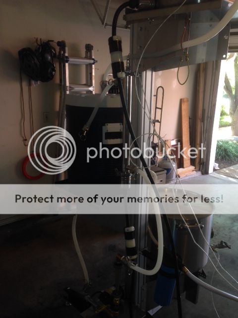
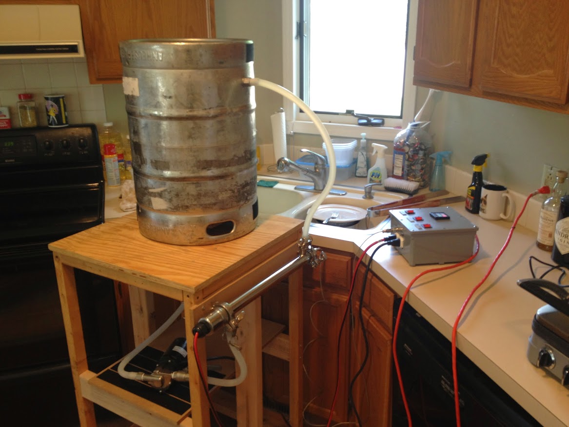
Here is the two-tier system I built for 5-gal batches. It has a 1500 W/120 VAC RIMS heater with MyPIN controller. Mash tun sits on a modified step stool. Chugger recirculation pump & RIMS tube are mounted to a modified aluminum work platform below the mash tun. The HLT and BK each have a 4500 W/240 VAC element and sit above on my loving SWMBO's awesome gas stove, making this a hybrid I suppose. Yes, the BK control goes to 11! Controller has a manual selector between the HLT and the BK, and it automatically interrupts current to the 240 VAC side whenever the RIMS element needs juice. System works great for low to medium gravity beers. Hope to bring a larger MT online in the near future to make high gravity beers easier.
View attachment ImageUploadedByHome Brew1429732725.102400.jpg
View attachment ImageUploadedByHome Brew1429732766.509668.jpg
View attachment ImageUploadedByHome Brew1429732801.786593.jpg
View attachment ImageUploadedByHome Brew1429733591.036745.jpg
 
rwc_617,
I am gathering the electronics to build a controller very similar to your design. I especially like your idea of the auto switch that interrupts your BK or HLT when the RIMS needs juice. Would you mind sharing your wiring diagram for your controller?
I also like your angled RIMs tube.
Thanks for sharing your design!
 
I also used flow sensors in my design but to cut the power to the rims element if the flow of liquid through it stops ... I used a $10 stainless flow switch to accomplish this and I also use a flow meter for a visual reference on both flow rate as well as color and clarity.
I took an idea I got from alphaomega and ran with it by using a stainless steel cartridge heater for the element. its 25" long and only 1000w (ULWD and 240v) but does a great job since it pairs up nice with my 24v DC pumps which only recirculate my mash through it at about 2 gallons per minute. I used a 1" camlock for quick disassemble for cleaning/inspection but so far after about 10 brews with it I have yet to get any buildup except the time I shut off the pump and forgot to kill the rims element (hence the reason for my flow switch...) the rims tube with flow meter and switch cost me about $125 to build. and I can drop the flow down to about .5 gallons per minute before the element automatically shuts off.... I have toyed with putting an alarm in to notify me of stuck sparges but in over 50 brew sessions with this setup and about 15 with my triple stage false bottom I have had none yet so...

here are more pics in my build thread below,

https://www.homebrewtalk.com/showthread.php?t=497593&page=10

IMG_20150116_221853%5B1%5D.jpg


IMG_20150116_221940%5B1%5D.jpg


IMG_20150116_221917%255B1%255D.jpg


IMG_20150227_093004_092.jpg


IMG_20150119_121616_140.jpg
 
Weird request, but I'm trying to figure out a sparge/mash recirculation option and would like to see some more pics of your silicone tubing recirculation arm. Could you post some more?

View attachment ImageUploadedByHome Brew1432176541.336095.jpgView attachment ImageUploadedByHome Brew1432176578.326872.jpg
Hafmpty, currently I'm using 1/2" silicone tubing for the RIMS return and 3/8" silicone for the sparge arm. I cannibalized a couple of stainless BBQ skewers and bent them such that they hold up the tubes just above the grain bed. For each tube, I used a silicone bottle stopper to plug one end and I used hollow punch to put holes along both sides of the tube for a fairly even spread of wort or water on the top of the grain bed.
 
LavaStream, my wiring diagram is on a different computer, but will try to post it soon. After I disconnect the supply and exit tubes at the end of a brew day, the uphill angle of the RIMS tube does drain well from the inlet port.
 
rwc_617,
thanks. the last of my electronic parts are trickling in.
cheers

LavaSteam, here are some of my wiring diagrams. I used a Normally Closed SSR (Crydom D2450-B), so that juice will be cut to the HLT or the BK whenever the RIMS needs juice. So far so good.

To simplify wiring, I used circuit breaker switches instead of relays. A 12V relay approach would have been cheaper and just as good, but my caveman mentality likes the simplicity of the breaker switches.

I'm familiar with thermocouples from a previous life so I use those, but RTDs are probably a little better and I may migrate that way someday. I like the way my SSVR works for BK control. One criticism of SSVR-BK control is for hop stands, but I can swap the BK element into the HLT controller and dangle a spare thermocouple in the BK during chill down and hold a steady temp. (I've tested it with water but not wort.)

Another thing I like about my setup is augmenting the 4500 W BK element with a 19000 Btu/hr burner on SWMBO's stove -- they really get 6.5 gallons of wort boiling pronto!!

One change I would like to do is on the Pump 1 wiring. In order to avoid scorching in the RIMS tube, I rigged the double pole switch for the RIMS element so that Pump 1 comes one whenever that switch is closed (one pole for the heater, the other for the pump). But since I have a three way L-type valve on the exit of Pump 1, I can divert wort away from the RIMS and scorch the heck out of whatever is still in there. I haven't scorched anything YET, but I would like to copy AugieDoggie's flow valve approach someday.

Good luck with your system, LS!

Slide01.jpg


Slide04.jpg


Slide07.jpg


Slide09.jpg


Slide10.jpg
 
rwc_617,
Thanks for the diagrams. I think I figured out most of the labels. L1-L6 are the lights, T1 & T2 are the termocouples or RTD. Are C1, C2, & C3 the heating elements in the RIMS, HLT, & Boil Kettle respectively? Are C4 & C5 the pumps? Is C0 the power into the controller?
I found a Crydom D 2450 on ebay, is this the same as the Crydom D2450-B that you used?
http://www.ebay.com/itm/Crydom-Solid-State-Relay-D2450-3-32vdc-in-240vac-out-50amps-/381010955685?
Thanks for your help with my controller build.
I like your sparge set up as well!
cheers
LS
 
View attachment 279454View attachment 279455
Hafmpty, currently I'm using 1/2" silicone tubing for the RIMS return and 3/8" silicone for the sparge arm. I cannibalized a couple of stainless BBQ skewers and bent them such that they hold up the tubes just above the grain bed. For each tube, I used a silicone bottle stopper to plug one end and I used hollow punch to put holes along both sides of the tube for a fairly even spread of wort or water on the top of the grain bed.


Sorry for the late reply. Thanks for the additional pics and info. I appreciate it.
 
rwc_617,
Thanks for the diagrams. I think I figured out most of the labels. L1-L6 are the lights, T1 & T2 are the termocouples or RTD. Are C1, C2, & C3 the heating elements in the RIMS, HLT, & Boil Kettle respectively? Are C4 & C5 the pumps? Is C0 the power into the controller? ...
LS

Yes. I use "C" for Connector.

...
I found a Crydom D 2450 on ebay, is this the same as the Crydom D2450-B that you used? ...
LS
No. That is a Normally Open SSR. You need the hard-to-find "-B" at the end to indicate that it is Normally Closed. I will try to find my source. BTW, that line is really only 120V relative to Neutral and to Ground, so you could use a D1240-B, but I never found one of those at a reasonable price. And the extra voltage and amperage capability of the 2450-B makes me feel better.

Good luck, and sorry to be so far off topic!
 
No. That is a Normally Open SSR. You need the hard-to-find "-B" at the end to indicate that it is Normally Closed. I will try to find my source. BTW, that line is really only 120V relative to Neutral and to Ground, so you could use a D1240-B, but I never found one of those at a reasonable price. And the extra voltage and amperage capability of the 2450-B makes me feel better.

rwc_617,
Thanks for your prompt answer to my question. I will look, too, for the Normally Closed 2450-B variety and dump the NC version from my eBay cart.
cheers
LS
 
Anyone have any thoughts on mounting it Vertically or horizontally?

As long as you build and orientate it so no air pockets get trapped inside it doesn't matter...

I finished and tested my new longer 40" rims tube using an 1800w certridge heater element a couple weeks ago and I get a solid 2 degree rise per minute with 5 gallons of water from 70 all the way up to a 154 degree where I had the setpoint... I'm done messing with it since this is perfect for set mashing.
I just kegged an oragnge wheat beer I made with it 2 weeks ago and I got about 80% efficiency..

Here are some newer pics, I moved the safety float switch as well as the pump location for the rims and the flow meter (amongst other changes.) not bad for a low budget build of under $200 in parts. the whole setup including kettles fittings ,control panel and rims comes in somewhere around $1000-1200..... (if you dont include the $400 or so in old hardware I removed during constant upgrades and fermenters and such) the last pic has my new larger 16 gallon boil kettleI just found on amazon with the bent lid rim for $89 shipped.

IMG_20150608_170136_563.jpg


IMG_20150623_153429_092.jpg


IMG_20150625_152422_354.jpg


IMG_20150623_153500_168.jpg


IMG_20150625_152404_599.jpg


IMG_20150623_153333_939.jpg
 
LavaSteam, here are some of my wiring diagrams. I used a Normally Closed SSR (Crydom D2450-B), so that juice will be cut to the HLT or the BK whenever the RIMS needs juice. So far so good.

To simplify wiring, I used circuit breaker switches instead of relays. A 12V relay approach would have been cheaper and just as good, but my caveman mentality likes the simplicity of the breaker switches.

I'm familiar with thermocouples from a previous life so I use those, but RTDs are probably a little better and I may migrate that way someday. I like the way my SSVR works for BK control. One criticism of SSVR-BK control is for hop stands, but I can swap the BK element into the HLT controller and dangle a spare thermocouple in the BK during chill down and hold a steady temp. (I've tested it with water but not wort.)

Another thing I like about my setup is augmenting the 4500 W BK element with a 19000 Btu/hr burner on SWMBO's stove -- they really get 6.5 gallons of wort boiling pronto!!

One change I would like to do is on the Pump 1 wiring. In order to avoid scorching in the RIMS tube, I rigged the double pole switch for the RIMS element so that Pump 1 comes one whenever that switch is closed (one pole for the heater, the other for the pump). But since I have a three way L-type valve on the exit of Pump 1, I can divert wort away from the RIMS and scorch the heck out of whatever is still in there. I haven't scorched anything YET, but I would like to copy AugieDoggie's flow valve approach someday.

Good luck with your system, LS!

Hope you guys don't mind if I chime in and some questions occasionally. rwc 617, What software are you using to draw your wiring diagrams/schematics?
 
Back
Top