the-crowing
Well-Known Member
- Joined
- May 8, 2013
- Messages
- 85
- Reaction score
- 4
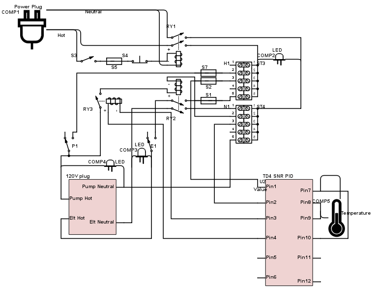
I'm planning out my 120V 20A single pump, single 1500W element RIMS system. Should be building it in the next month or two. Looking for some pointers and a sanity check on my schematic. Sorry, it's kind of a mess. I used Digi-key's online schematic builder because it's online and free  . Anyway, I'll describe what I'm trying to accomplish.
* S3 is a key switch that will fire contactor RY1. I'll have a 1A fuse (S5) and emergency stop button (S4) feeding this contactor coil
*H1 is the hot bus, N1 is neutral
* S7 will be a 1A fuse which will feed switch P1 for a 12V pump. 12V adapter will be plugged into 120V outlet
* When the switch for P1 is on, it will also supply 120V to relay RY3. RY3 is controlled by the PID. When the PID fires this relay, it will feed 120V to contactor RY2, allowing RY2 to supply power to switch E1 for the 1500W element. I did this so the element can only turn on if the pump is on.
* S1 will be a 15A fuse for the 1500W element
* I did not show any grounds wired but they will be wired from the power plug to the 120V outlet and terminated on a metal enclosure.
Any feedback would be much appreciated!
Also, anyone have suggestions for a better schematic program?

* S3 is a key switch that will fire contactor RY1. I'll have a 1A fuse (S5) and emergency stop button (S4) feeding this contactor coil
*H1 is the hot bus, N1 is neutral
* S7 will be a 1A fuse which will feed switch P1 for a 12V pump. 12V adapter will be plugged into 120V outlet
* When the switch for P1 is on, it will also supply 120V to relay RY3. RY3 is controlled by the PID. When the PID fires this relay, it will feed 120V to contactor RY2, allowing RY2 to supply power to switch E1 for the 1500W element. I did this so the element can only turn on if the pump is on.
* S1 will be a 15A fuse for the 1500W element
* I did not show any grounds wired but they will be wired from the power plug to the 120V outlet and terminated on a metal enclosure.
Any feedback would be much appreciated!

Also, anyone have suggestions for a better schematic program?


