
silverbrewer
Well-Known Member
The parts for this Mk 2 pump are so far pretty much hand made. All of this could be done if you enrolled in an evening course at the local engineering college, which shouldn't cost much. The Mk 2 pump build will indeed need some access to engineering equipment, but down the line, once this Mk 2 pump has been well and truly tested, there is no reason why a Mk 3 pump cannot be designed that uses only simple readily to hand parts.... so that anyone can make one, with a tad of ingenuity and a simple toolkit!
I was being shown a brand new brake drum the other day that would have been a good starting point, but the bloke at work was only showing it to me because he had recently put a .22 bullet through it with his rifle! While he was chuffed that it had gone right through one side and dented the other, I was looking at it and thinking "****, I could have used that you berk"....My point here is that brand new brake drums cost very little and give a perfectly machined circular surface.
On my Mk 2, all the shafts are silver steel, which is already ground to exacting tolerances, so it fits the bearings exactly with no work required except cutting them to length. (Note here that metric silver steel is machined to a plus nothing, minus a couple of thousanths, while imperial sizes might be a plus or minus tollerance, so bearings may not fit and you will have to go with metric) I was lucky with the steel tube for the rollers....that is also ground, so cleaning it up to get a good surface took a few minutes with 800 grit paper.
The arms on my Mk 2 are cut out of a very hard foam that our 5 axis guys use to carve car models out of....... but they could just as easy be made from wood. The shapes were drawn by hand and cut on a simple band-saw. The round hole cut in the middle of each part is so I could hold each part down on the top slide of my lathe, using the tool post bolt. I then drilled one of the shaft holes with a 15 mm drill stuck into the lathe head. I then indexed the cross slide the appropriate amount and drilled the other shaft hole. that way, the shaft holes were all drilled exactly the right distance apart, and they were parallel, and not skewed either. Fine slots were cut in the bases of each leg and holes drilled for the clamping screws.
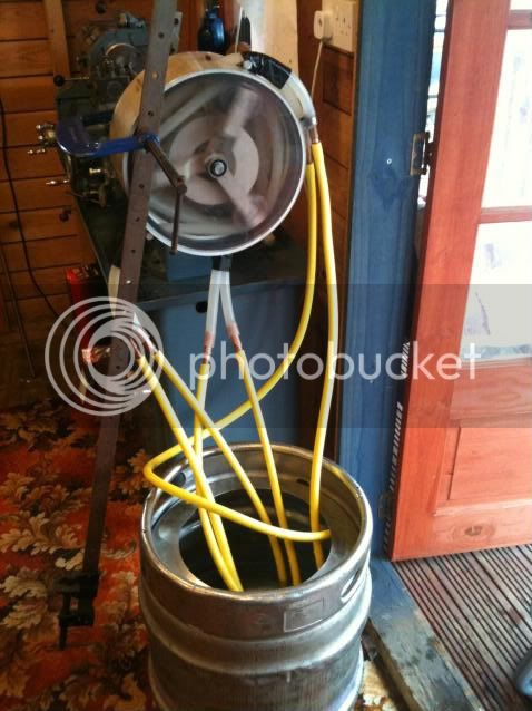
The end plates for the big tube will have to be made on a BIG lathe, so that could be a stumbling block for this design to be made by one and all, so those without access to a machine shop will have to wait until Mk 3
I was being shown a brand new brake drum the other day that would have been a good starting point, but the bloke at work was only showing it to me because he had recently put a .22 bullet through it with his rifle! While he was chuffed that it had gone right through one side and dented the other, I was looking at it and thinking "****, I could have used that you berk"....My point here is that brand new brake drums cost very little and give a perfectly machined circular surface.
On my Mk 2, all the shafts are silver steel, which is already ground to exacting tolerances, so it fits the bearings exactly with no work required except cutting them to length. (Note here that metric silver steel is machined to a plus nothing, minus a couple of thousanths, while imperial sizes might be a plus or minus tollerance, so bearings may not fit and you will have to go with metric) I was lucky with the steel tube for the rollers....that is also ground, so cleaning it up to get a good surface took a few minutes with 800 grit paper.
The arms on my Mk 2 are cut out of a very hard foam that our 5 axis guys use to carve car models out of....... but they could just as easy be made from wood. The shapes were drawn by hand and cut on a simple band-saw. The round hole cut in the middle of each part is so I could hold each part down on the top slide of my lathe, using the tool post bolt. I then drilled one of the shaft holes with a 15 mm drill stuck into the lathe head. I then indexed the cross slide the appropriate amount and drilled the other shaft hole. that way, the shaft holes were all drilled exactly the right distance apart, and they were parallel, and not skewed either. Fine slots were cut in the bases of each leg and holes drilled for the clamping screws.
The end plates for the big tube will have to be made on a BIG lathe, so that could be a stumbling block for this design to be made by one and all, so those without access to a machine shop will have to wait until Mk 3


")
