canyonbrewer
Well-Known Member
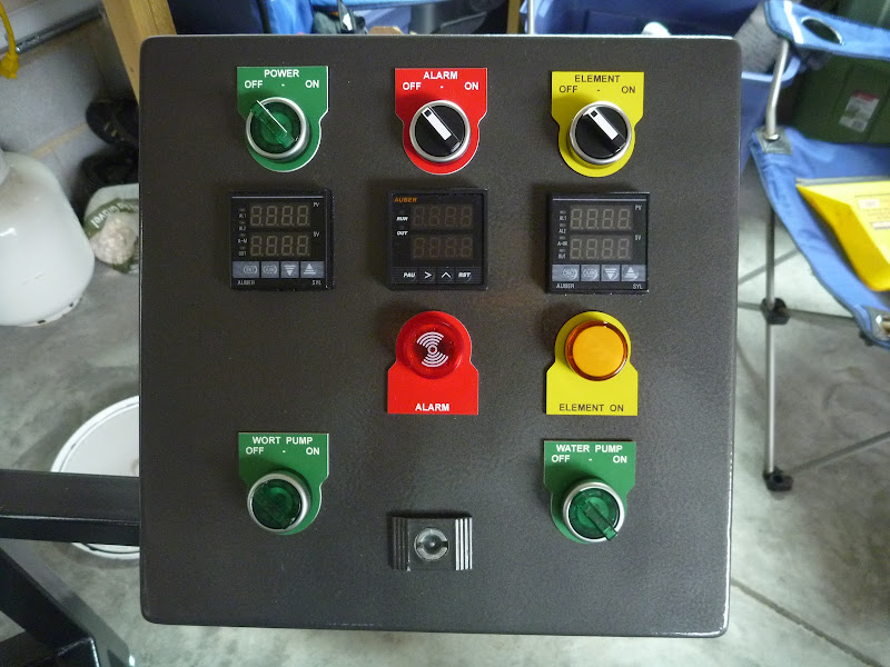
final touch on my control panel...some tags:

U mean this
http://www.midwestsupplies.com/stai...ort-chiller-w-garden-hose-fittings-50-ft.html
That is 1/2 od. .436 id + .03 +.03 = .5ish
So you want a 1/2 compression.
final touch on my control panel...some tags:

canyonbrewer said:Mine is 12x12x8
canyonbrewer said:Mine is 12x12x8
bgarino said:I was admiring your stand and was wondering what the dimensions are?
This is a great setup! I have a few questions. How long are your temp probes? I'd like to mount mine like you did going straight into the tee and have the hose coming straight down. I wasn't sure if you used 1.5", 2", or 2.5" probes from Auber.
Also, any issues with mounting your panel so it opens up? I was debating doing that so I could have a better layout but people recommended to just make it work opening to the right or left.
did you notice poor flow rate with the trub filter? I am having issues with a poor flow rate but I think it might be something wrong with my dip tube.
edit: Also do you notice a problem with priming the pumps? I had to add a tee with another valve to help bleed the air out.
Have you yet determined why you're getting a 4-5 deg difference with your thermocouple? *
Did you extend the wires or use any plugs or connectors between your sensor & your PID controller?
If you did that could be the source of the error. *
Thermocouples are made from the junction of 2 - wire consisting of different alloys. *The junction can be as simple as twisting the two wire together but is normally made by fusing them. *The junction is normally enclosed in a stainless steel tube but this isn't a requirement unless the medium being measured will react with the wires. *
When you extend the wires from a thermocouple you MUST use THERMOCOUPLE wire Made of the same alloys. *K - wire with a K - thermocouple. * If you use another alloy such as plain copper you have formed another junction. *This junction is another thermocouple in your system & can cause errors. *A common way to calibrate your sensors / controller is to use an ice bath & set the reading to 32-F or 0-C. * If you use copper wire to extend the thermocouple leads you now actually have 3 separate thermocouples in series. * From the meter's positive terminal through the sensor back to the meter's negative terminal it'd look like this:
Meter + to copper to (Cu / TC+ junction) TC+ wire to (TC+ / TC- junction) TC- wire to (TC- / Cu junction) copper wire to Meter -
Each junction can be sensing a different temperature & can generate errors in your readings. *If you calibrated the system with the sensor in a 32-F ice bath the other 2 junctions are measuring ambient or possibly some other temperature. *Now start your heating your kettles where your sensor is. *When you put all of these junctions in series you get a real mess. *
Ideally you want to make sure you have the correct sensor, wires, connectors, etc. *Then calibrate at 32-F / 0-C water ice bath and at 212-F */ 100-C boiling water. * If all is well you shouldn't have errors in your readings. *I would invest in a certified scientific mercury thermometer to verify the mid point readings. *
*
You can also purchase thermocouple plugs & connectors.
McMaster Carr sell thermocouple supplies in small quantities.
http://www.mcmaster.com/#thermocouple-cable/=hq7i5w
Enter your email address to join:
