I'm so close to being done with this build I just have an electrical question but for future users searching I might as well give a brief outline of the build so far.
This model is the updated FRC445GB model from best buy (snagged it on sale). I'm putting two pin lock cornies in which will fit with flattening the door and removal of the thermostat/light fixture on the side. I've installed a tower on top following Schnitzengiggle's build. He outlines his build very well.
Things where I deviated:
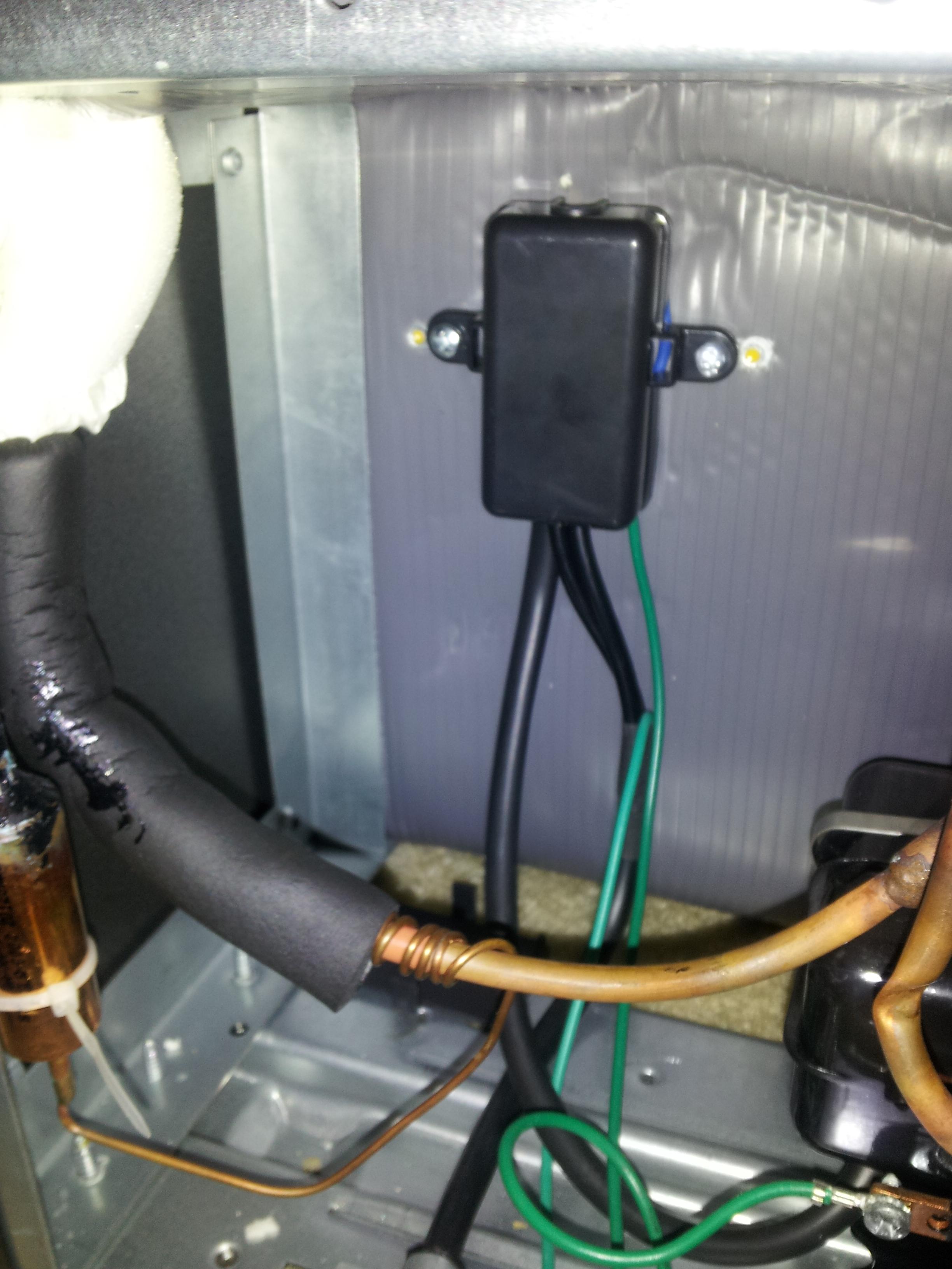
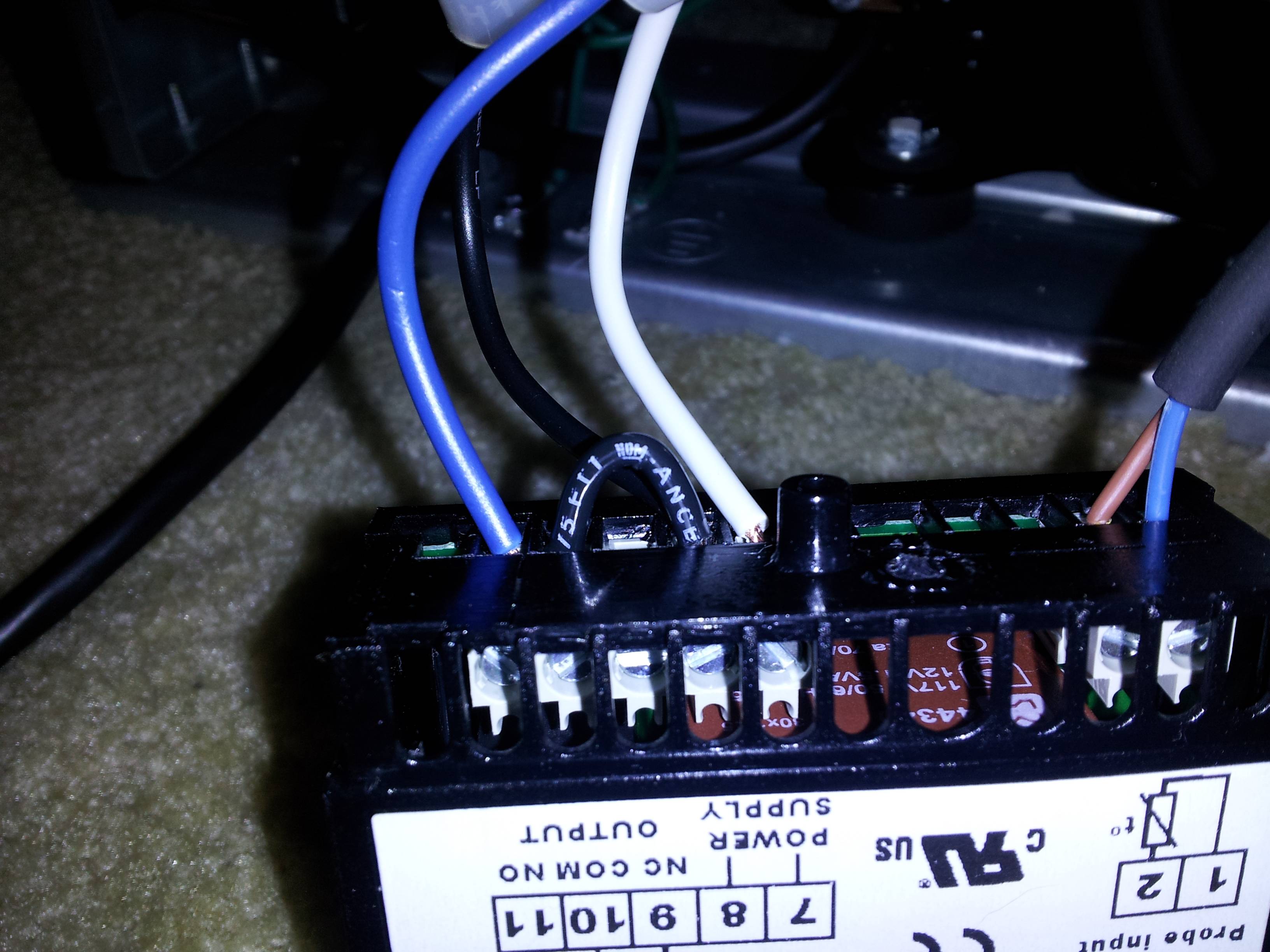
Anyway now onto a part he didn't do. He left the thermostat that came with the fridge in there just pushed to the back outside of its housing. I don't want to do that. I've got a Love controller I'd like to install. My thoughts are to install it on the back where the compressor is, run the temp probe inside through the drain hole, probably stick it in a bottle of that gel stuff that comes in ice packs (saw another build that did this, can't find the link now). But before I start cutting wires, I want to confirm some stuff and ask some questions. I apologize in advance for my crappy paint skills, hopefully these diagrams aren't confusing.
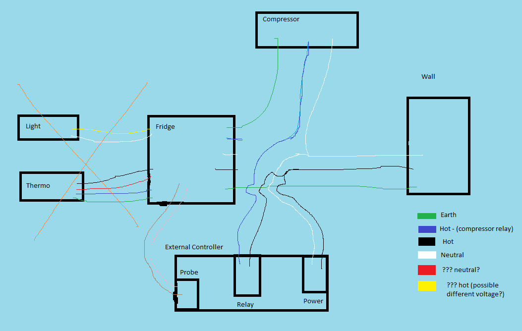
This is the wiring as it is now as far as I figure:
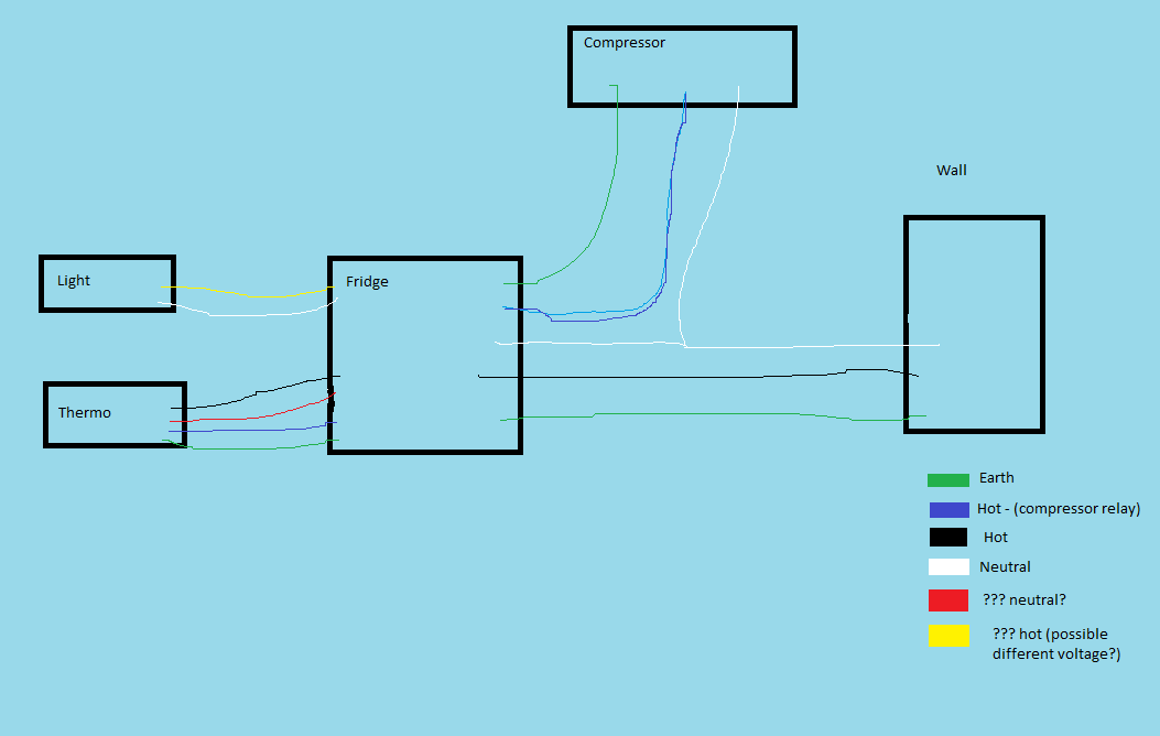
The light and thermo inside the fridge.
I figure black goes into the thermo through a relay that when switched on connects to blue and completes the compressors circuit. I think the thermo itself is powered through the hot(black) and neutral(red). I'm not 100% sure because it seems to me they'd use a white wire there. I'm also guessing this light bulb is a 12v light bulb.
Also if this is wired up how I think then can I do the following to control it with my controller?
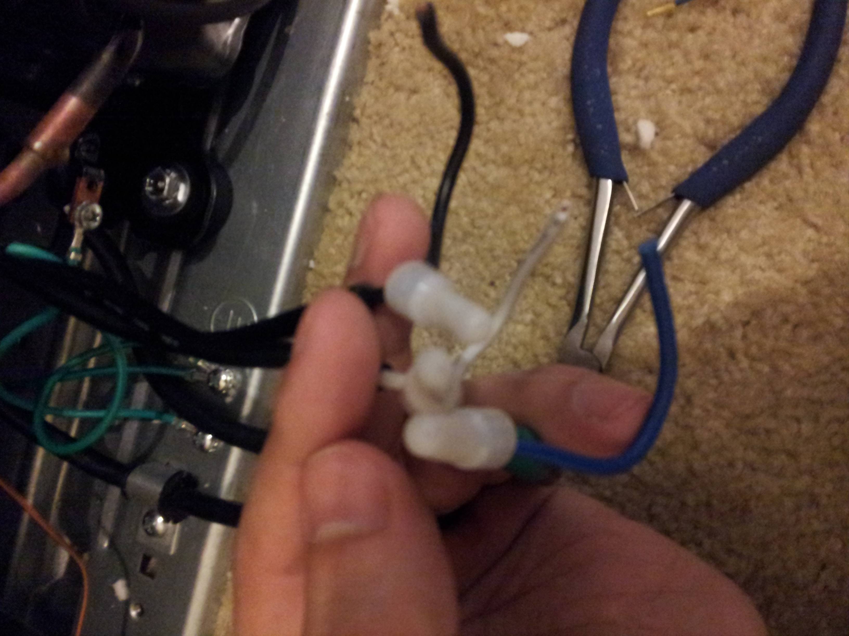
The thermo and light are disconnected and just dead wires now.
Also has anyone confirmed the voltage of the light bulb? I can't quite plug it in right now to measure.
I'm thinking that if I just cap the wires inside but leave them hot then later I can come back and add in a 12v fan from the white and yellow to push air up into the tower.
This model is the updated FRC445GB model from best buy (snagged it on sale). I'm putting two pin lock cornies in which will fit with flattening the door and removal of the thermostat/light fixture on the side. I've installed a tower on top following Schnitzengiggle's build. He outlines his build very well.
Things where I deviated:
- I drilled the two holes much closer together. I noticed in his pics the two pipes inside of the fridge appeared to be angled like /\ and I guessed it was because they were too wide for the tower. Putting them right next to each-other seems to fit perfectly vertical.
- I did not use nearly as much wood. I just picked up a hardwood cutting board (just happened to walk by and it was about the right size). I think it was like $5 and somewhere around 10x15".
- I cut slightly deeper into the foam when placing the board so that I did not need to cut away the plastic top to make it fit flush again. I plan on completely replacing this soon with a better top (build pics included on that one!).
Anyway now onto a part he didn't do. He left the thermostat that came with the fridge in there just pushed to the back outside of its housing. I don't want to do that. I've got a Love controller I'd like to install. My thoughts are to install it on the back where the compressor is, run the temp probe inside through the drain hole, probably stick it in a bottle of that gel stuff that comes in ice packs (saw another build that did this, can't find the link now). But before I start cutting wires, I want to confirm some stuff and ask some questions. I apologize in advance for my crappy paint skills, hopefully these diagrams aren't confusing.
This is the wiring as it is now as far as I figure:
The light and thermo inside the fridge.
I figure black goes into the thermo through a relay that when switched on connects to blue and completes the compressors circuit. I think the thermo itself is powered through the hot(black) and neutral(red). I'm not 100% sure because it seems to me they'd use a white wire there. I'm also guessing this light bulb is a 12v light bulb.
Also if this is wired up how I think then can I do the following to control it with my controller?
The thermo and light are disconnected and just dead wires now.
Also has anyone confirmed the voltage of the light bulb? I can't quite plug it in right now to measure.
I'm thinking that if I just cap the wires inside but leave them hot then later I can come back and add in a 12v fan from the white and yellow to push air up into the tower.