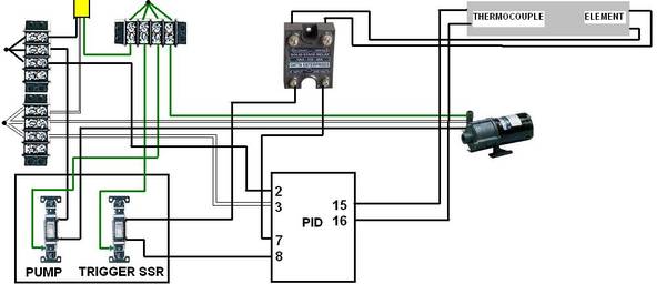
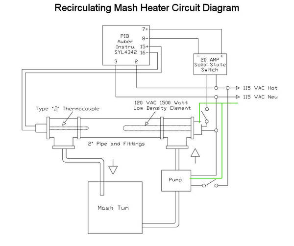
I know that a lot of people here recommend switching the element itself rather than the SSR, since SSR's can fail in the closed position, sending power to the element even when it's supposed to be off. Wouldn't take much rearranging in your diagram.
I'm probably not the right guy to ask, since I'm just figuring all this stuff out myself, but the diagram looks pretty straightforward to me.
Red flag!
The SSR is not supplying power to the element. Think of the SSR as a switch. It controls power input to the element. The diagram shows both SSR output terminals connected directly to the element. Where is the power feed?
Oh hey, that was my crappy attempt at a wiring diagram. Never did do the the rims system. At that time I didn't really understand how the ssr worked as pj pointed out. U will also need to run a neutral to the element since its 120. Also as the other guy said u may want to put the switch on the output of the ssr to protect against current leaking / the ssr failing closed.
Okay so I went with the diagram from RIMS for dummies and added a switch after the SSR to control the element. I also added in the ground, which is going to go to the pump and element and the two switches correct?