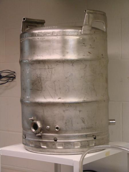
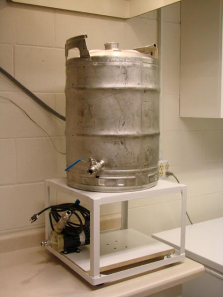
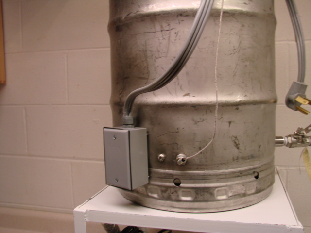
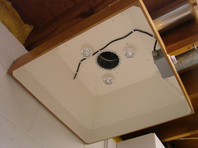
My electric brewery is finished, at long last. I began the design phase in mid-2007 by lurking and asking questions on a couple of forums, the greenboard and this one. I completed the construction phase about seven months ago, and have brewed nine times on the new system. I have not attempted to document each step of design and construction as diligently as some of you have, but I took some pictures that I am posting.
Before getting to the pictures that I am sure you are just dying to see, I do want to thank the countless individuals who knowingly or unknowingly contributed to my project design and execution. I cant name them all, because I didnt always record where an idea came from, or whose design I copied, but I expect you will recognize your handiwork or answers when you see the pictures.
DESIGN CRITERIA
1. All electric fired, so I could walk away from it if I needed to; I used to brew with propane and never left the room when the flame was on, for safetys sake.
2. Semi-automatic no, not like an AK47 but enough controls so that I could set temperatures or boil rates and duplicate them reliably and repeatably.
3. Able to fit into my pre-existing brewery, the half of the utility room my patient wife gave me.
4. Efficient moisture extraction, i.e., no dripping cold water pipes in the utility room
5. Maximized safety risk management.
DESCRIPTION
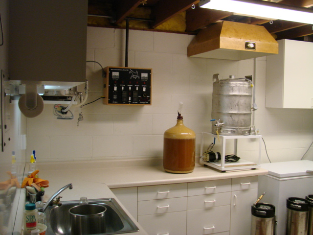
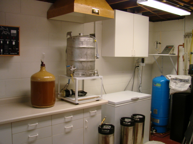
My brew space is approximately eight by twelve feet, with an L-shaped counter and storage.
The cabinets are for storage of equipment and supplies. The sink to the left in the picture was put in specifically for brewing purposes, and has softened hot and cold water as well as un-softened cold water plumbed in. The countertops are the brewing surfaces, and some of the brewery is built-in, unlike many systems I have seen that are mobile or portable. I enjoy indoor brewing, particularly here in Minnesota in the winter and during mosquito season (when its not winter).
Instead of just describing my build, Ill describe my brewing process, and then the equipment. This may make clear why I designed it the way I did. Or not.
PROCESS
I have a private well; the water tastes great, but is hard and alkaline. I treat the brewing water with calcium hydroxide to soften it, other salts to suit the style of beer Im brewing. I dont filter it because it has no chorine or iron, and tastes good.
A brew day starts the day before, when I fill the treatment tank (the white tub beside the sink in the photos above) with 12 gallons of hard well water for a five brew, or 20 gallons for a ten gallon brew, then pump the HLT full (7 gallons), and heat it to about 110 or so. I then drain it back into the treatment tank to warm all the water to about 75 F. Then the treatment salts are dissolved or suspended in a quart of the warm water and mixed into the tank. This precipitates the alkaline bicarbonate ion as calcium carbonate. That night I pump the HLT full again, neutralize the water in the HLT with phosphoric acid to pH 6-7, and either set the timer to turn the element on before I get up, or just turn it on when I get up.
`
I mash in by gravity, and use a blue cooler for my MT. The remaining water in the HLT is boiled for use as mashout water. Then the HLT is refilled, neutralized and temp set to 180 F for sparge water. I started batch sparging the first few brews, but found that purging air out of the hoses and pump between sparges was a pain. So now I fly sparge, and only have to fight the air out of the system once. During sparging the wort is pumped up to the BK, which is elevated on a stand about a foot above the counter. I use a CFC chiller, gravity fed to my fermenter which is a 6 gallon Better Bottle or a 6.5 gallon acid carboy. If I need to, I use a water bath heated with an aquarium heater to maintain fermentation temperatures.
more in the next post


