A couple of people asked how to do the wiring of the switches to get the forward and reverse functionality.
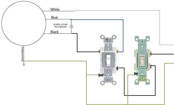
Here's the wiring diagram that is on the website that sells the motor:
You can see that the only difference in forward or reverse is which side of the capacitor (blue or black wire of the motor) you have the voltage source connected to.
You need a 3-way switch, and a regular switch to pull this off....
edit: or a SPDT (single pole, double throw) switch with a center off position... see next post.
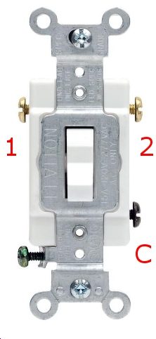
Below is a pic of a 3-way switch. Check your specific switch to identify which screw is which, but the basic principle is that there is one screw that is the "common" terminal. This is where your 120v comes in (labeled "C" in the pic.) With the switch in one position, current will be allowed to flow from "C" to the screw labeled "1". When you flip the switch, current is allowed to flow from "C" to the screw labeled "2".
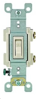
This is a standard switch. When it is in one position, no current flows. When it is on the other position, current is allowed to flow from one screw to the other.
You use the normal switch as your main power switch, running the 120v hot line through it and then connecting to screw "C" of the 3-way switch.
You connect screw "1" of the 3-way switch to one of the motor's wires, either blue or black, just pick one. You connect screw "2" to the other wire.
The two switches together now form a path from your voltage source to the blue or black wire, depending on which way the 3-way switch is flipped.