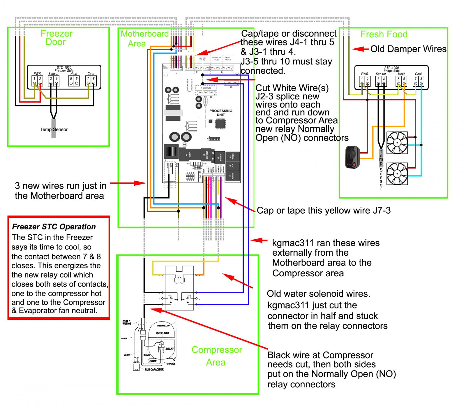
Wiring help please, side-by-side fermentation/ kegerator

Homebrew Talk - Beer, Wine, Mead, & Cider Brewing Discussion Forum

Help Support Homebrew Talk - Beer, Wine, Mead, & Cider Brewing Discussion Forum:

This site may earn a commission from merchant affiliate links, including eBay, Amazon, and others.
To fit the wood cover I took a glass shelf from my pile of parts off the fridge, cleaned it up and held it up to the opening.

I drew out the hole locations and the main opening on it.

Then I taped papers together and placed them on the glass and traced using a back light. (If you have tracing paper, that is probably best, but I had papers handy from the manual / schematic).

From there I placed the paper on the wood, and drilled the locations. (I was not all too worried about precision as the wood is forgiving.

To attach I will be installing it all with what I have on hand. 1/4-20 2.5" bolts. (Note that if I were able to easily remove the entire plastic ring from the door, I would not need this long of bolts.

(I don't have pictures on hand for the cut outs / location of the STC's)

View attachment 1427245777928.jpg

View attachment 1427245797085.jpg

View attachment 1427245824186.jpg

View attachment 1427245838209.jpg

View attachment 1427245850764.jpg
 
Looking good kgmac311. Thanks again for the replies guys. I'm hoping to get started this weekend.
 
I was able to get the unit final wired, and.... it runs!
At first I was alarmed because nothing was happening. However I recalled this happening last test and just needed to wait out the delay in the STC's. (Default delay is 3 minutes)

I sprayed in some foam around the tap cutout and filled in other holes. I used cardboard to keep it from expanding on my controllers.

I moved it to it's home slot in the garage and all that remains is to get the shelving installed and put the door handles back on.

View attachment 1427683864923.jpg

View attachment 1427683886870.jpg

View attachment 1427683903303.jpg
 
Oh, ya. I forgot to post a pic and description of the wires I ran for the fridge side temp probe.

I routed it up the door from the controls and out.
I located a good place to drill down thru the top of the freezer into the compartment.
Then I routed it around inside the freezer compartment and thru the center divide. From there I attached the stc supplied probe.

(Splice point at the hinge area incase the door needs to be removed)

View attachment 1427684426709.jpg

View attachment 1427684450868.jpg
 
Update.
I am ecstatic that this thing is working smoothly!

It took a couple of days to tune it in. I needed to get the temperatures to stabilize and then focus on getting the probe temp calibrated.
I took 2 baby food jars and drilled a hole in the lids large enough for the probe to run thru. I then filled each with vodka and applied putty to the lids at the probe wire. (I actually used some silly putty as that was readily available, just don't tell my kid. Besides, he has 2 other containers of that stuff.)
I took a remote temperature sensor that is pretty close to accurate (my outdoor temp sensor for my house.) and set it next to the jar in the side I was testing. I would tweak the temp a little at a time and get it dialled in and move to the other side.
Today it appeared to be spot on to the settings I programmed it to and holding.
Next portion of the project is to re-install some of the shelving and whatnot. I ran a few things thru the dishwasher to get them cleaned up.

I'll post more pictures after I get some of the guts put back in.

I really have to give credit to @cas3439, because I really don't think I could have brought this mutt to life without his help!
Slánte Cas3439 :mug:
 
Glad to hear that thing is coming along nicely! The pics look great so keep 'em coming! I am happy to help out a fellow brewer!
 
Oh, ya. I forgot to post a pic and description of the wires I ran for the fridge side temp probe.

I routed it up the door from the controls and out.
I located a good place to drill down thru the top of the freezer into the compartment.
Then I routed it around inside the freezer compartment and thru the center divide. From there I attached the stc supplied probe.

(Splice point at the hinge area incase the door needs to be removed)

Not ragging on you in the least or anything... every time I get something done on my build, I go "****, i should/could have done x instead of y". But you could have used a molex connector or something for about $.60 and have an easier disconnect than the splice. Just an idea for anyone else attempting something similiar. :mug:
 
@cas3439

It turns out my wiring is a little different. I hadn't noticed until after I had wired everything and made my cuts in the door.

I knew the controls were different but assumed that if wired like @kgmac311 with settings set all the up to 9 it should work the same.

Turned it on and control center had no power. Only then did I think to look at the wiring diagram supplied to discover that the control board taps into the freezer door wires.

My next thought is to use wiring from the ice maker.

What are you thoughts?

Thank you for your help

Wiring.png
 
@DirtyBurd
Just a couple of questions.
1. So what you are saying, there is some sort of control board on the freezer door?
2. Do you plan on leaving it there?
3. How big is it? Maybe snap a pic of it.

Since you already cut the wires from the control board on the back of the fridge, could you remove the FF Tactile Control Board from the freezer and connect it to the main board J4 1-3 connectors. You would have to protect the board so it didn't short out (Maybe put it in something and tape it to the back of the fridge since it looks like its all low voltage) then you would be able to use the freezer wires like you wanted.
 
I have this fridge : http://www.applianceaid.com/pictools/gefridge2.pdf

I assumed the "tactile" board was was the touch control wires because after I wired everything up it doesn't work any more (doesn't light up). I haven't tested voltage or continuity because I ran out of time last night.

It just doesn't make sense to lose power their after wiring. I'll look at it tonight and take some pics.

Thanks again
 
@DirtyBurd,
Perhaps a silly question,,, are your connections fully seated? Anything wires left open/ not attached/ spliced?
Pictures are probably needed to guide the answer a little better.
Question for clarification on "control center".
Do you mean the freezer door OEM tactile?
The units OEM temp controllers located in the FF side?
Or your after market temp controller(s)?

I did have what appeared to be an issue twice. STC's are pre programmed to have a 3 minute delay between switching. (Also I had wires swapped once that failed to operate the system correctly)
 
What all do you have wired? Have you wired in a relay?
I do not understand how you would have sent 120 to this controller. None of these wires were tinkered with on my build. I do not recall if they were 12v or not.
If you can, test the unit by disconnecting the 2 plugs at the control, with the compressor wiring reconnected (eliminate the relay if installed).
This should make the unit run in a failsafe type mode.

It does appear that your model is the same as mine, with a change in control panel.

Perhaps start a new thread with all the details and pictures of your build and give us a link to it.
Your build may require unique and additional assistance.
 
View attachment 269701

My fear is that it runs on low voltage (see wire colors) and that I blew it out by running 120 to it.

I think you are right DirtyBurd, and I do see how it could have happened with the way your original fridge controllers are wired to the same wires that run to the freezer door. I'm sorry you didn't see the schematic earlier. How much is a new controller? I didn't see your exact model number so I couldn't look it up, but they look to be around $50
 
First off...you guys are awesome!! This was by far the most complete thread on this subject, that I have been able to find. Thank you! I'm getting ready to tackle this same project and I think that I have a pretty good handle on it. I do have one question though. Anyway that you could clarify fan placement for me? Description and pics. Thanks again. Cheers.
 
Hey sorry to bring this thread back from the dead, but the have the very same fridge and I am in the middle of the same conversion. Big thanks to @kgmac311 and @cas3439 for all work they have done.

My question is the damper wire that you used to supply power to the controller and then on to the fans and heater, is only 22 awg. This seems very light to be using for that much power. Same thing with the wires in frezzer door there also 22 awg, I know this side is only running a relay.

My plan was to use the I maker power and ground as there much larger wire, or run a new line up the back and in the water filter hole.

Let me know if i am worrying about nothing.
 
I used the skimpy wires in the freezer door, no problem. As you said, they are only powering the controller and switching the relay. So far so good. On the fridge side I got power from the light bulb just above the door. Much heftier wires. I saw this on one of the other conversion threads. It has been working great. Good luck!
 
Yeah, I'm not sure about the wire size kgmac used since I never actually saw his build l. I can tell you on mine I did use the Ice Maker power wire for that very reason (a bigger wire) to power the heater and fans.
 
Back
Top