Wiring help please, side-by-side fermentation/ kegerator

Homebrew Talk - Beer, Wine, Mead, & Cider Brewing Discussion Forum

Help Support Homebrew Talk - Beer, Wine, Mead, & Cider Brewing Discussion Forum:

This site may earn a commission from merchant affiliate links, including eBay, Amazon, and others.

user 201787

Active Member
Joined
Nov 17, 2014
Messages
36
Reaction score
2
Good day all,
I am still quite new to the site and home brewing.
Before me is a feat I need some assistance on. There are a good number of like builds, however they all appear to have different wiring/ controls than my combo.
My over all build will have 2ea STC-1000's, one to controll the fermentation (fridge) side (fan from cold air / heat source). The other is to control the freezer portion.
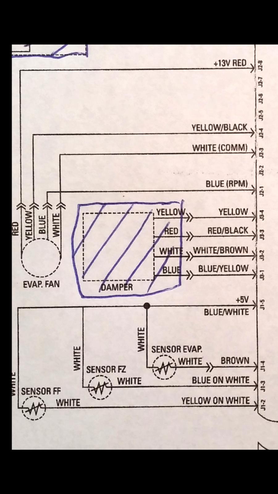
The trouble is, I am no AC electrician and the schematics elude me. Or is there info missing?
I need to know how to splice in the STC to effectively replace the stock freezer controller and perhaps disable the fridge controller.

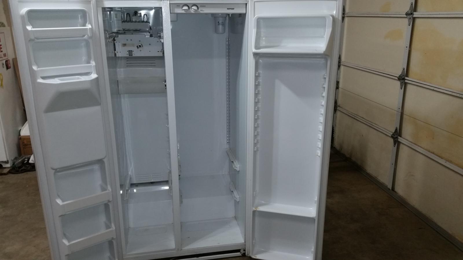
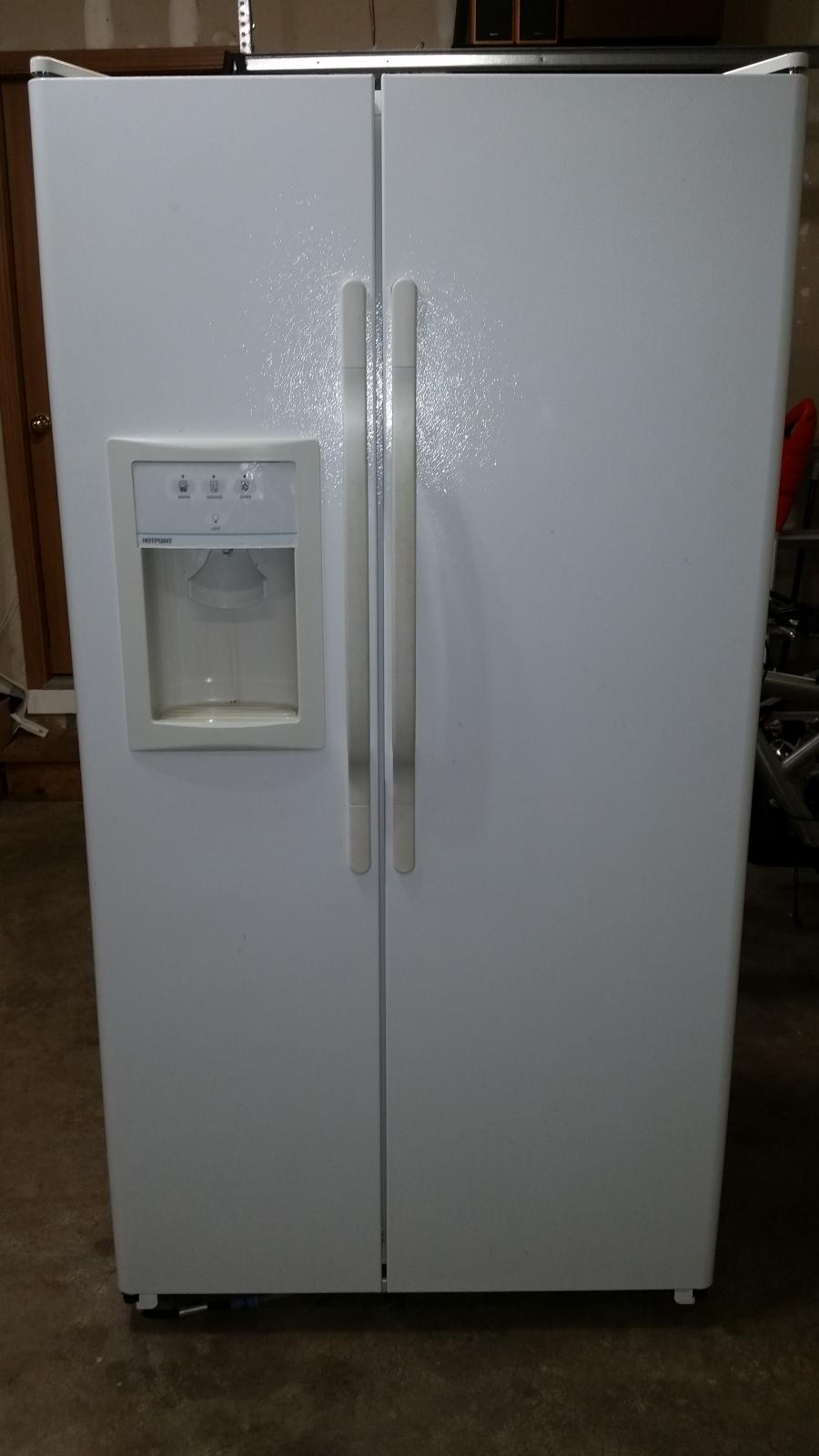
Hotpoint (GE) model HSS25GFPJWW
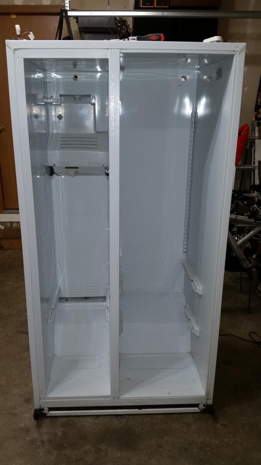
Items removed:
Fridge damper
Freezer ice maker and door dispenser.

Pictures:
Overall schematic
Controllers and diagram

View attachment 1423440037578.jpg

View attachment 1423440129388.jpg
 
I am going to attempt to gather a plethora of people here that have fought this build, and won.
It is my hopes that someone of the following may have insight for me:
(I thank you in advance!)

USER NAME (Built post date)
@Boerderij_kabouter (2/23/09)
@Forbein11 (2/4/10)
@rtrevino (5/4/11)
@mikeal (5/16/11)
@drkwoods (10/26/11)
@Cas3439 (12/22/11 & 3/26/12)
@mistercameron (12/24/11)
@sean_close (7/14/12)
@blakeseven (11/26/12)
@fork (4/22/13)
@bluedog_brewing (6/13/13)
And there are more I am sure, but I may not have written the name down or come across the thread.
 
I wish I could help. hang in there someone will catch this thread that has done this before!!
 
I've been doing some research for your build. With you having the board circuitry for the temp sensors, you are going to have to do something like Bluedog Brewing did, that is interrupting the hot wire going to the compressor. I don't think that you want to cut into the wires of the Temperature Controller circuit board.
I found this snippet on the AppliancePartsPros.com website under GE Refrigerator Repair Guide. "Temperature Control:If your GE refrigerator is not running, the temperature controls can be your problem. To check this, unplug the refrigerator then remove the cover from the controls located at the top front of the fresh food section. There should be a plug that connects both of the controls, unplug it. Then plug the refrigerator back in and if the refrigerator runs after you disconnect the controls, the controls are bad and need replacing. With the controls disconnected, the main board will operate the refrigerator at normal setting. This will give you time to get the part to fix it. If however the refrigerator will not work after disconnecting the controls, your problem is elsewhere."

To me this means if you did cut the wires to insert your STC-1000, the main board would see the interruption as a problem and just run the refrigerator at the medium settings, even if the STC-1000 wasn't calling for cooling. You could actually try this out and see if the fridge runs without the Temp Controller Board plugged in.

Back to what Bluedog Brewing did. He left the Temp Control Board intact but turned both of the setting dials up to max (9), so that the freezer & fresh side would always be calling for cooling. That way when the STC-1000 was calling for cooling, the compressor would kick on because the freezer side would be above 32 degrees (for serving temps) and the Temp Control Board is trying to get it somewhere way below freezing. Which brings up another thing. Don't mess with any of the Thermistors or their wiring. Another snippet from the same website. "Most of these GE refrigerators have three thermistors: one in the fresh food section and two in the freezer. Some have four or more thermistors depending on the model. If any of the thermistors are bad the performance of the refrigerator will be greatly reduced or it may not run at all."

I know his system works but reading up on the STC-1000, it says they have 2 10 amp contacts. I don't know the Full load amps or current of your refrigerator (it should be on the sticker inside the fresh food section) but my black and red kegerator only pull 6.5. That being said, I think you could go without the external relay and just use the STC-1000 to switch the compressor hot wire. I don't think you really need to switch the evaporator fan to keep the temps even in the serving side, that should be more important in the fermentor side. Also one thing I don't know is does the evaporator fan ever run on its own without the compressor running? With his setup it won't turn on even if it was trying to without the STC-1000 calling for cooling. Bluedog- I'm not bashing your way at all. No hard feelings, like I said, your way works, but I think it can be done another way.

kgmad311 let me know a couple of things:

1. What the full load amperage is from the sticker?
2. Do you plan to put both STC-1000 on the same side or one per door like I did?
 
Fantastic info! And thanks!
I even attempted to seek info on a appliance repair forum. They were reluctant to assist as it was not a repair. I figured it never hurts to ask.

The sticker says 11.2 amps.

I know thru tinkering, that the compressor and fan run when the controls are unplugged. Its like a limp-home mode I suppose.
(Note that all sensors are also removed due to cleaning, and are on hand still for possible reuse if needed)

I had anticipated placing both STC's in the fridge door due to local power and possible splice location of the controls.
However I know now that this source and splice location just got bumped. The STC locations are subject to relocation. I had even thought of putting then in the control housing inside the fridge. The drawback of that is lack of display visibility.

Just lastnight I was attempting to determine what wires to splice from the controller disconnect. Note the operative word of attempt. (No nothing fried, just was not able to determine what wire combo interrupts the compressor)

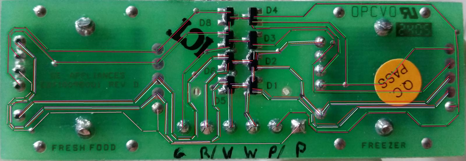
Below are pictures of the maim circuit board. This is just as confusing to me. There is. Not a schematic for the board.

I'll be pondering the info and interpreting the schematics for a possible outcome.

View attachment 1423852994312.jpg
 
Well with the 11.2 amps it pulls, I would say that you should go with a relay like Bluedog did since the STC-1000 is only rated @ 10 amps. It doesn’t look like they are very expensive (under $20).

As far as the STC-1000 locations I think I would just put one on each door. To me it eliminates the confusion on which one is for what side primarily. It leaves the fridge side a little less hectic to wire without the other controller there. Also to put one on the freezer side is pretty cakey using the wiring already going to the ice/water on the door. There should be 5 wires going there, and you’ll only need 3 of them to get the job done. Another bonus is that if you have to take the doors off, the disconnect on top of the door is nice. The other side is always a pain in the a$$ because I always hard wired everything over to the door. When/if I do another I will put some sort of disconnect on the Fresh Food side also so I don’t have to tear the door apart to get to the wire just to take the door off. I guess if I just stopped moving all the time it would alleviate my problem.

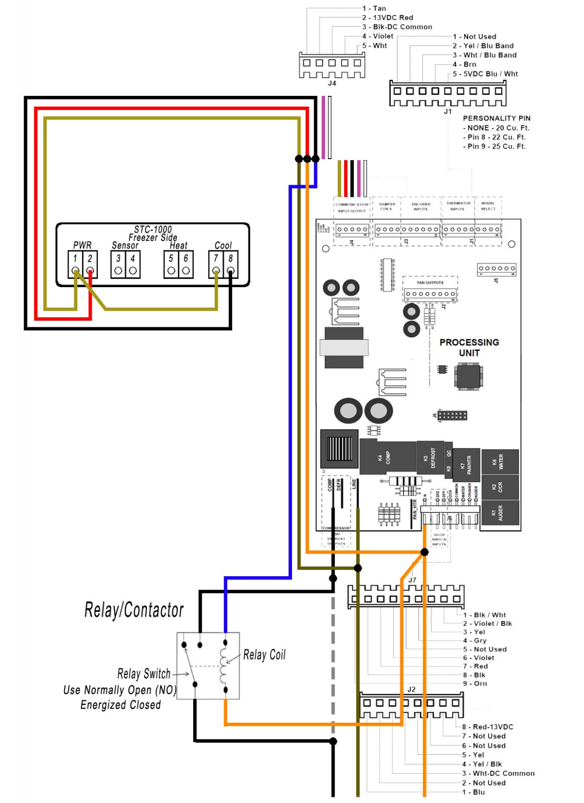
Just to be clear, I am in no way responsible for anything you do. Just have to protect myself. Now, first unplug the fridge! So, to wire the freezer side controller on the freezer door (first tear out the water/ice crap from the door, and leave the wires coming down thru the door intact. See my build for a couple of pics https://www.homebrewtalk.com/f252/side-side-fermenter-keggerator-316056/ . On the Motherboard at the back of you fridge, disconnect the J4 connector from the board. It should be the top left side connector and should be the colors listed below. If they are not those colors let me know. This book says this is just a sample and to see what came with your fridge. I see you have a schematic but it’s kind of blurry to read. These are the wires that go all the way to the freezer door and they will no longer have their original purpose of running water and ice since those mechanisms are gone. We are going to use them to power the STC-1000 and run a signal to the relay/contactor (you have to buy one) coil to close the contacts so the compressor will run. Cut the connector off so you can spice wire onto them. I always like to leave a little wire going to the connector just in case I have to splice it back together for some reason, but not necessary since it doesn’t look like much slack there. Connect a new wire to the black J4 wire and then to the new Relay on the Hot side of the coil (the blue wire in the drawing).
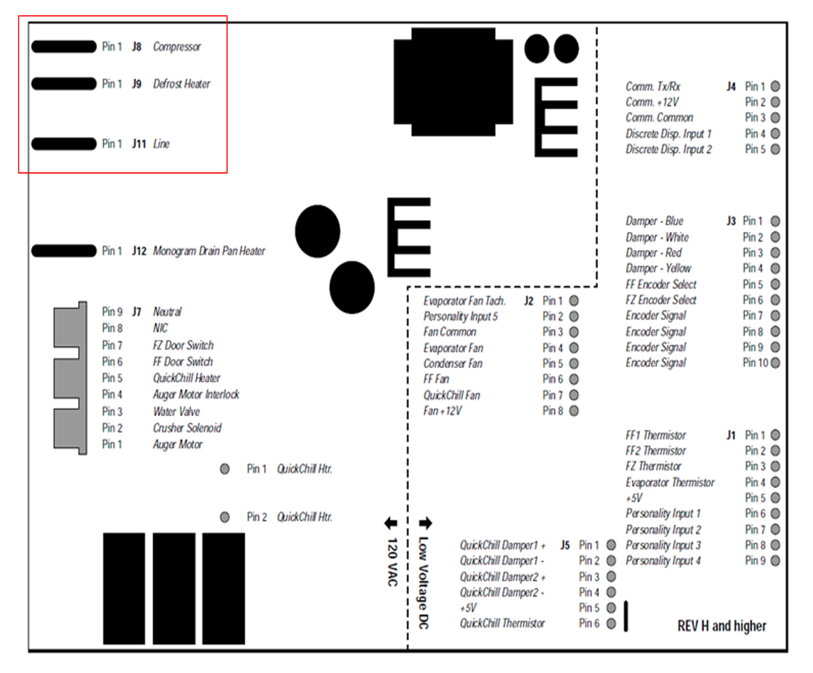
Next we need to get the hot wire that runs to the compressor to we can put the wires on the new relay contactor. That wire should be on the bottom left of the Motherboard, the one with the blue connector and it should be the black wire (J8). We have to leave this wire connected to the board so leave enough that you can splice onto both ends after you cut the wire. It doesn’t look very long, maybe it’s possible to pull in a little more from where it goes into the fridge? Mount the relay somewhere and run wires off of the Normally Open contacts back to each side of the J8 wire. This will cut the power to the compressor until the STC-1000 tells it the relay coil to energize thus closing the relay contacts and completing the circuit to the compressor.

To get power to the STC-1000 and to the relay coil we need to cut the Brown wire (J11 Line) under the same blue connector as the compressor wire and splice in a new wire and connect it to the Tan wire of the old J4 connector wires. The Neutral side comes from the Orange wire under the J7 connector at the bottom right of the motherboard. Splice into that wire like you did the others and run one wire to the Neutral pole of the relay coil and one to the Red wire of the old J4 connector wires.

That should get you started. I’ll look at the Fresh Food side next. I would put the thermistors back in the system once they are clean so the system isn’t on Limp-home mode. You want it thinking it has to get real cold by using the control knob turned up to 9.

When you get a chance take a picture of the wires that come into the control housing of the Fresh Food side and maybe list the colors they are.

Freezer Control Hookup kgmac311.jpg


Board Connector Location Pic.jpg
 
Just to be clear, I am in no way responsible for anything you do. Just have to protect myself. Now, first unplug the fridge!

Hilarious!!!! No worries,,, Ill add to that and state that I am responsible for my own actions and, especially when they are preceded with "hold my beer".

So, in disassembly, I have gutted the freezer door to include snipping off the pig-tail on the door side. (The connectors are still in-tact on the main body!)
So I can at the least use the pass thru hole in the hinge area of the door to connect to the connectors atop the fridge body.
(Great point of having disconnect points!)

I have to assume you are a draftsman, or have these diagrams pulled from another source with some personal touches for wire routing.

I am quite happy and grateful for the time you are giving me and this thread! You are providing me with MUCH data and info!!!!
I am working OT this weekend and may not get much time to apply the info you provided.

As for the FF side:
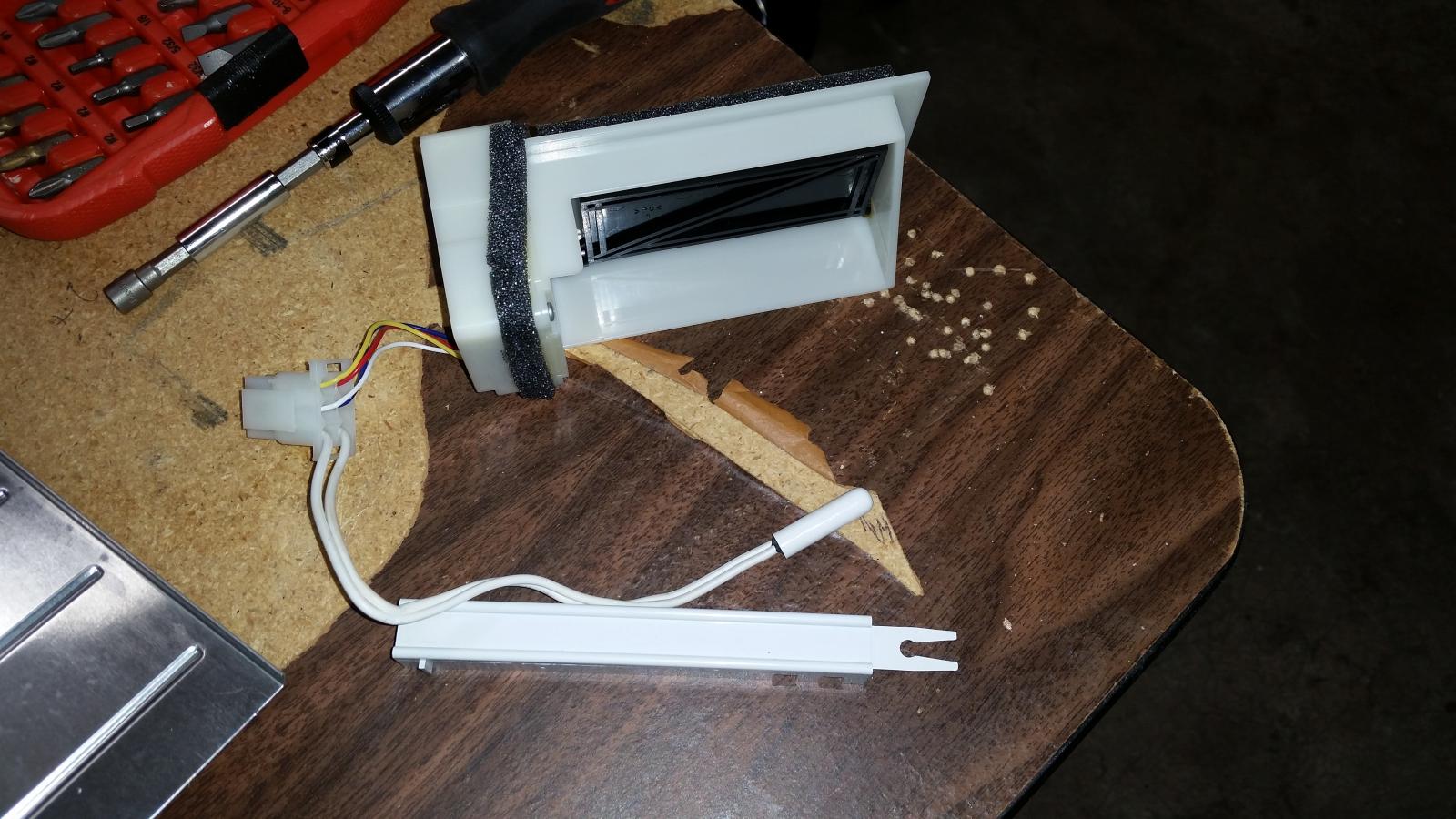
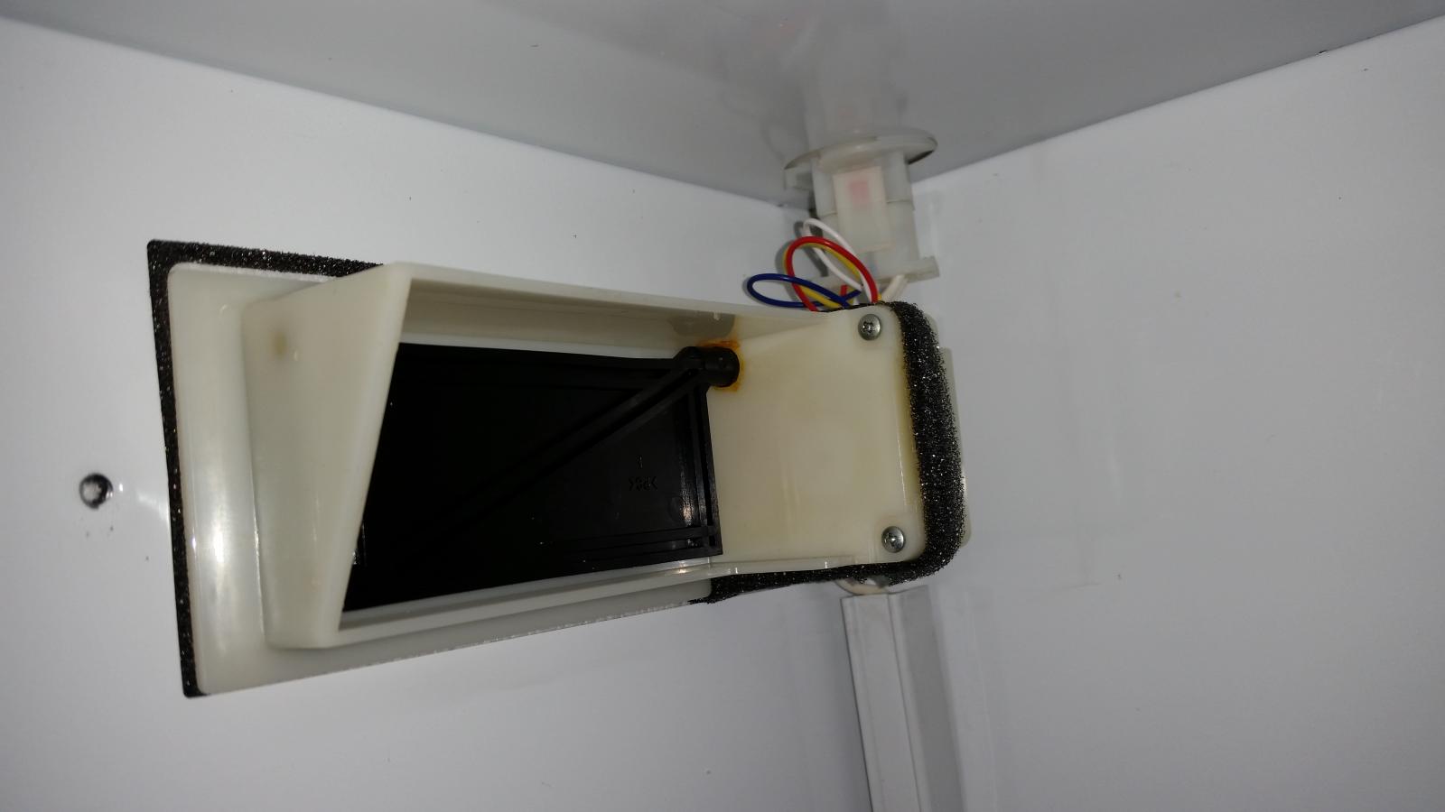
The colors are Yellow, Red, Blue, White that run the damper/ probe.

20150205_231845.jpg


20150204_234053.jpg


2015-02-13 18.57.28.jpg
 
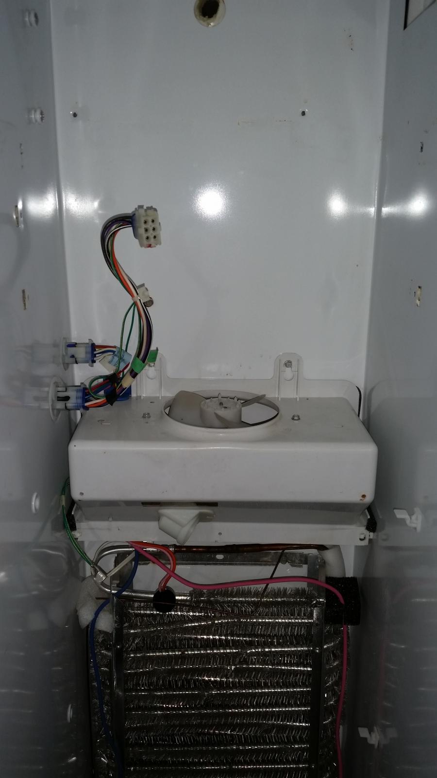
Being that I am working hard at hardly working right now (on lunch). I thought I would share a few more pictures of the unit. These are not the most recent ones. (I have washed it up and removed some more of the rails). The upper shroud over the fan in the freezer section will be going back in (as well as the coil cover). I just have them out for cleaning and operational testing.

20150204_231613.jpg


20150204_231843.jpg


20150205_232722.jpg


20150205_234543.jpg


20150204_233000.jpg
 
Love the "Hold my Beer"! I should be busy this weekend myself, but have some time over coffee. It sound and looks like its coming along nicely.

I am not a draftsman, but an electrician in another life with a firm grasp on Photoshop! I keep forgetting to attach the link for the manual I found for this thing. I will post it later for others to look at if needed.

I don't see it anymore so you must have caught the mistake of the motorcycle contactor you mentioned and edited in your last post. You need a contactor with 120 volts AC. I know the motherboard does put out some low voltage but don't think that add a contactor to it would be good.

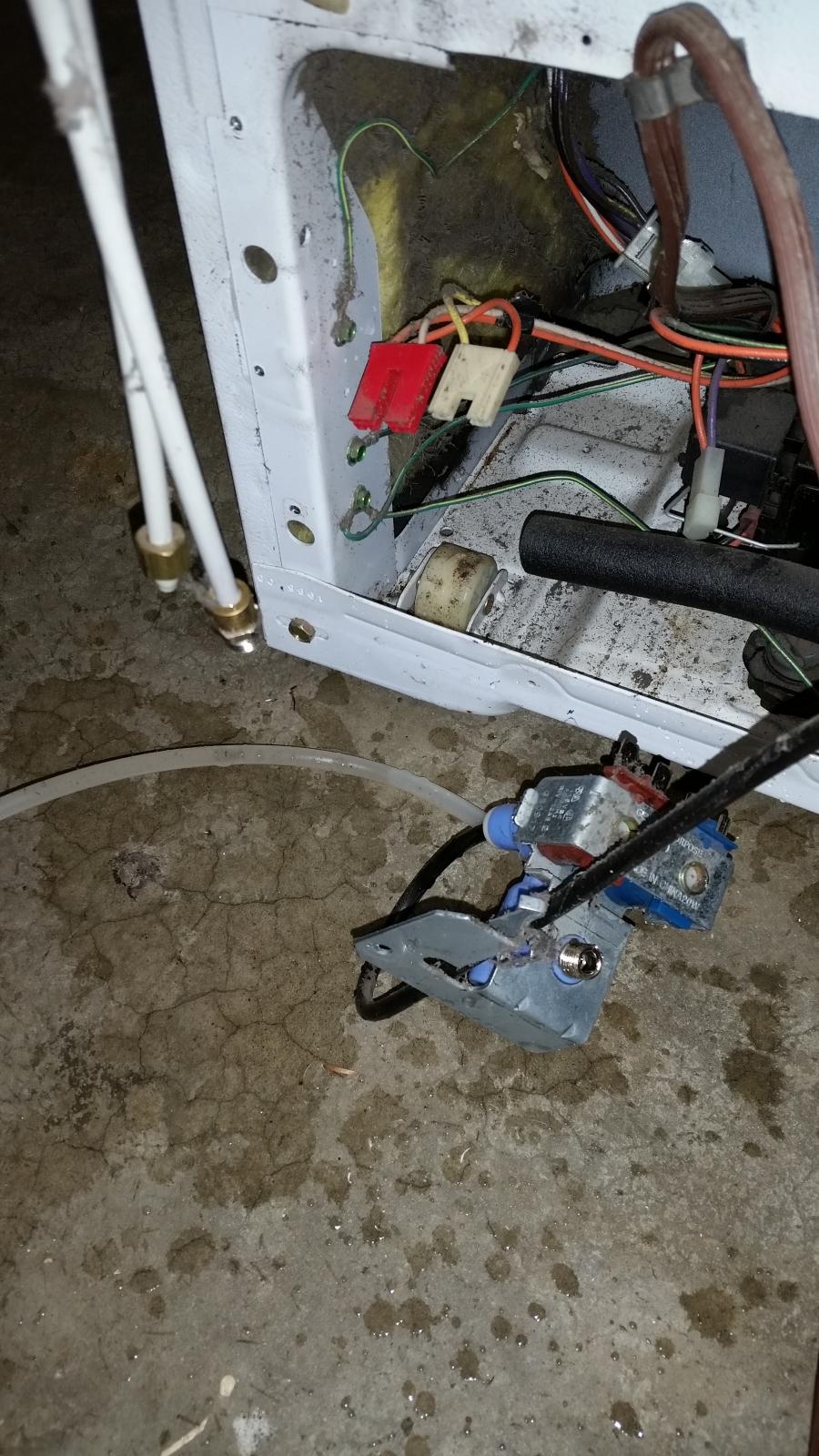
I like the last pic of the old water & ice solenoids. It reminded me that I used those wires in one of my builds. That area would be a great place to mount the new contactor. Those 3 connectors should be available to use now. Looking at the schematic we can use the old solenoid wires on the contactor. Save that solenoid bracket you may be able to mount the contactor on it.

I'll have to modify the original wiring schematic if we can use the wires going down there. My only fear is the limited space in the motherboard housing to splice wires together.
 
Ya right after I hit submit I thought to myself: "You moron,,, AC not DC...!!!" and promptly went back to edit out my lapse in judgement and show of temporary mental retardation.

I do still have the bracket on hand for just this possible situation. I kept all the junk thus far (except for the tubing) for that "just in case" situation for a re-use in some manner.

I do still ponder just how the controllers work. Do you suppose that they mix signals and effectively connect wires/ circuitry? As you pointed out and confirmed, when the connector of the controls are disconnected (thus leaving an open circuit), could this mean that the selectors may multi-select wire circuits at the same time? My original thought was that it would select a hot wire 1 at a time and link to a neutral. (single pole - multi-way rotary) However I am pondering this to be a multi-pole - multi-way rotary.

What are you thoughts on this?

I am in no way photoshop smart, and used the tools my (work) computer had to attempt to map the circuitry of the switch cb. (It took me a few lunch breaks to do) I may be dead wrong on this and probably am. It looked to me that there were commonalities so I tried to determine where they all went.

mapped2.jpg
 
I can't find where I read up on these to post. What I essentially got out of it was that depending on where the controllers were set, depended on the amount of constant voltage going back to the motherboard. So if that was true, then cutting or interrupting them to go to the STC-1000 would just put the fridge in Limp-Home mode or running even when the STC-1000 wasn't calling to cool.

Here is the Technical Service Guide I initially found.
http://www.applianceaid.com/pictools/gefridge1.pdf
 
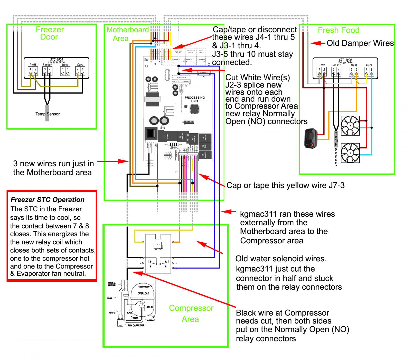
Here is the revised drawing moving the New Relay to the compressor area. I also stuck the Fridge side STC-1000 wiring on it. You should end up with 6 splices/wirenuts in the motherboard area. I didn't add any switches to the fans or heater to keep it simple but would recommend using them. Make sure they are rated for 120 volts if you use them. They are nice if you have the door open doing stuff and don't want those things running. My next build will also have a switch for the compressor side as well. Another guy I helped build one put his switches on the outside below the controller. If anyone sees a problem with anything let me know.

Both controllers schematic kgmac311.jpg


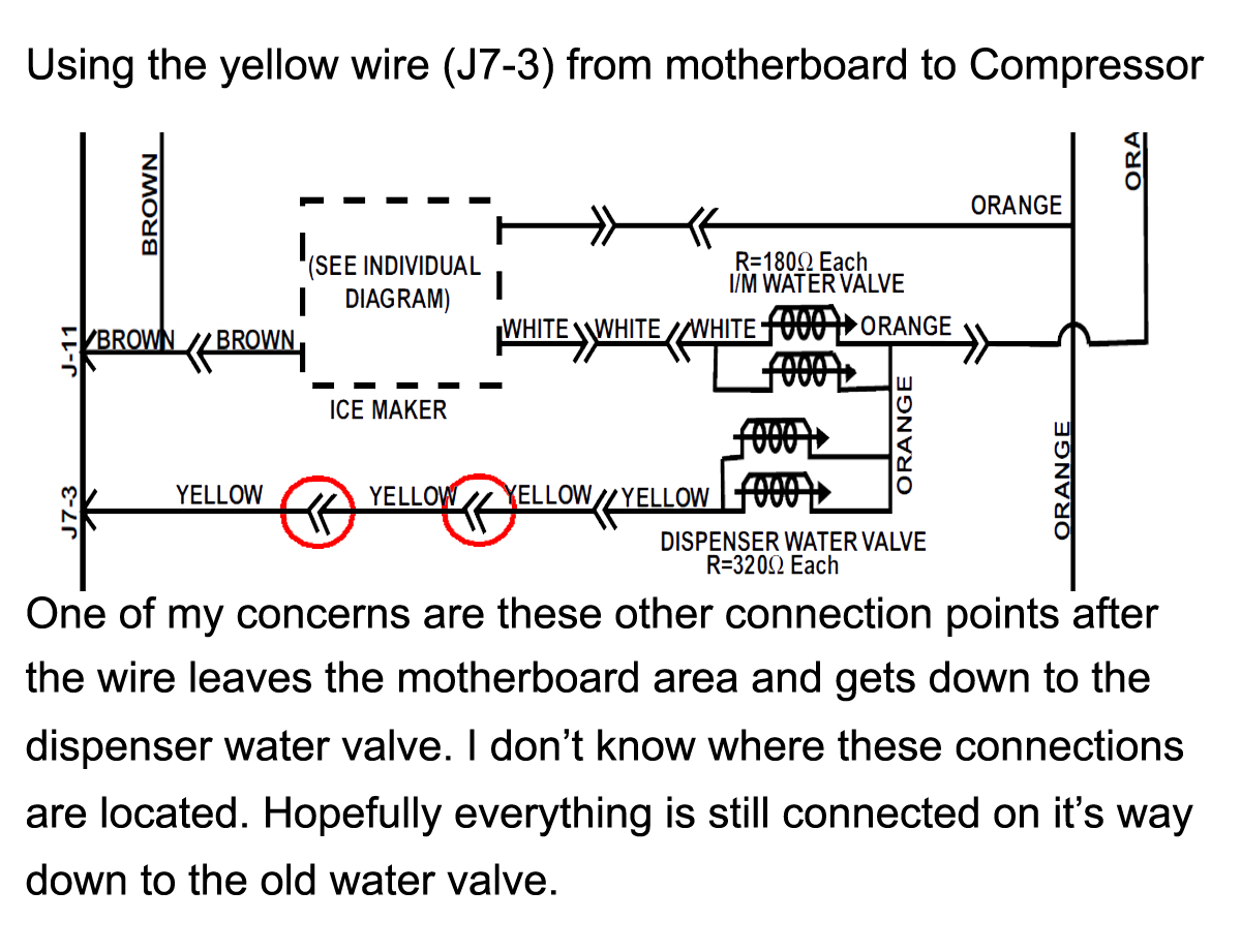
Other Water Valve Connections.jpg
 
@cas3439
Question on using a wire that can run from the motherboard to the ice maker harness.
If I mount a relay in the area of the motherboard:
I can splice into the compressor wire placing the relay inline and splice into the orange off of the j7 in lieu of the water solinoid.
In doing so I can also splice the STC(s) into the brown/ orange power at the ice maker harness.
The only wire I need to "route" is the one you show splicing from the yellow wire at j7.
Now to the question...
What wire is common from the mother board area to the ice maker harness that can be cut and re-used to run that switching wire?
If I understand it correcltly I could cut into a existing wire (v/b or w) off of the j3 and not cut into the yellow.
However I do not know what circuits these 2 wires may be connected to that may be vital to not cut.
Or I can run a solitary wire up the back of the unit thru the water supply hole to the STC from the yellow as your schematic shows.

Thanks

View attachment 1424500406607.jpg

View attachment 1424500419332.jpg
 
I'm not sure I understand what you are trying to do. When I modified the drawing, I moved the relay to the compressor area so you didn't have to mount it by the motherboard. Could you put it there, yes, but I figured it would be more protected in this compressor area, and not mounted out in the open by the motherboard where it's exposed electrical connections could be harmful. Theoretically it should be in some sort of enclosure, where someone or something couldn't touch those connection points. Putting it down in the compressor area at least protects it more than sticking off the back of the fridge.

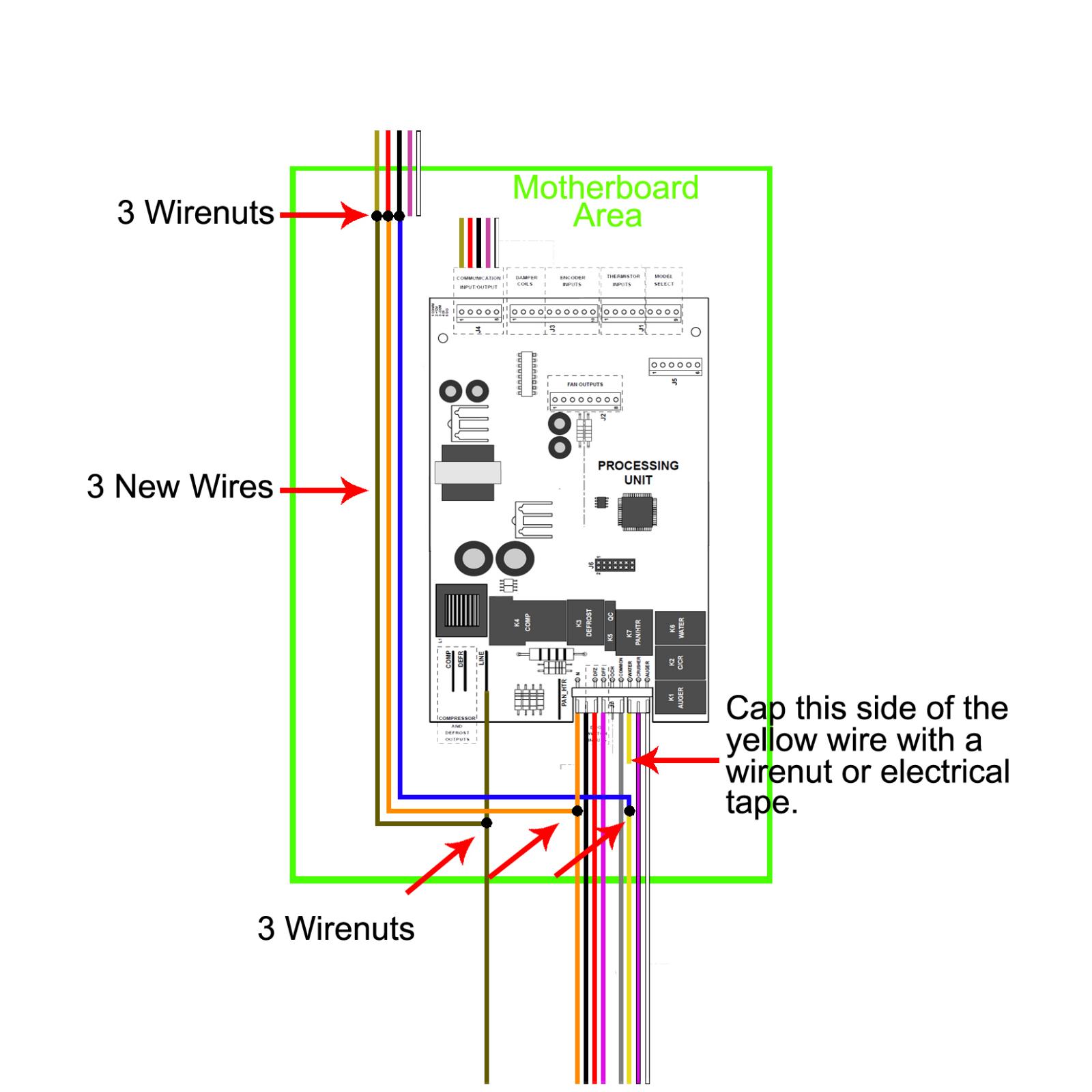
Also in the new drawing, you don't have to "route" any wires anywhere. All of the cutting and splicing takes place in the motherboard area using 3 new wires and 6 wirenuts. Doing it this way will preclude you from having to run any wires outside of the unit (i.e. thru the water supply hole. That's where I ran my CO2 hose into the freezer compartment, so the CO2 bottle could be on the outside not taking up room inside).

Maybe I just threw too much at you with everything on the one drawing. I made another picture of the motherboard enclosure and de-cluttered it.

I hope this clears it up better for you. If not post your question another way.

Motherboard Area Connections kgmac311.jpg
 
I misinterpreted the original and thought I would need to route new wires exterior from the motherboard and the color change was at entry/ disconnect point.
 
Well, crap.
I have the (omron g8p-1c4p) relay on the motherboard cutting the system about 1 second after plugging in the unit.
(The relay is directly above the comp/ defr/ line)

All routing is as depicted in the schematic, with temp wiring at the freezer door hinge area to the STC.

My only thought is the yellow repurposed wire is no longer in communication with the motherboard. (Uninstalled the yellow from the connector for new wire attachment.)

I don't think that it's the 3 wires from the J4 that were repurposed. (R, Br, Bl. These were also uninstalled from the connector)

I isolated the system back to near OEM with the new relay removed, black wires jumped back together and the STC removed. Only leaving the new splices in the motherboard area in place.
 
Did you try by-passing the yellow wire entirely by running a temporary wire right to the relay?

Did you plug the temperature controls back in?

Did you put the thermistors back in after cleaning? I see there is a thermistor attached to the damper connector. is that connected back up?

Was there more than 1 connector going to the Ice Maker? Looking at the manual, it looks like it. I'm pretty sure that the pic a couple of posts up (#15) with you holding it is one of them. What are the wire colors of the other one if it exists?

Are there any connectors you disconnected that have yellow wires?
 
All good and trouble shot now.
I was up against 3 things.
The fisrt was the fridge controls needed to be all the way up and set to stun.
Second was that I had the STC power supply wires swapped. (Thus not allowing a full circuit for the switching side to provide power to the relay)
Third was the compressor delay time set in the STC.

I realize that the compressor fan and the internal fan for freezer never stop.
Is is advised to or not to use the relay for the compressor fan? There is a black wire running directly in route with the relay location.

I also started in on the freezer door. That's been fun with all the foam getting static cling to just about everything.
In 20/20 hind sight I really do regret cutting off the wires at the top of the door!!! The modification for the door would be near its end already! However, I will attempt to fish new wire in.

My though is to have no need to cut more of the door for the STC's. I would like to put them in the closeout/ tap area.

I really appriciat your guidance time and advice @cas3439!!!!!!
 
Great news! Yeah I knew the controls had to be turned all the way up to 9, since you always want the thing to think it needs cooled. Glad you figured out the STC power goof, as I would never have got that without some pics. Be careful with the compressor delay time and do some reading on that subject. You don't want that thing cycling too much and burn out the compressor.

I'm not sure about the compressor fan running all of the time. I posted a couple of questions to Bluedog on his build thread because there are some confusing things for me. We'll see what he says and continue from there.

All of that foam is a pain to work with. I was glad I had a shop vac for easy cleanup every once in a while. I didn't get from one of your past posts that you actually cut the wires at the top of the freezer door!!! What were you thinking? lol That really sucks. Are you going to be able to put new wires into the old connector?

It looks like I'm reading you are wanting to put both STCs in the tap area of the freezer door. I think it would be possible considering that you still have 2 unused wires going to the freezer door.

It's been no problem with the guidance, time & advise! It's definitely hard to try to help like this without actually being there to look at things or just to do simple things like using a meter on the wires!
 
I'm still in though process of the location on the FF controller. I have a few route options in mind. I was going to open up the manual link you posted some time back and investigate the 2 remaining wires atop the door and the ff damper open wires.
I suppose I could have sprung for a Love controller and had this all figured out :).
I'll be chipping away at this thru the week if/ as time permits.

I am watching the other thread you posted the question in.
 
Just filling in some of the gaps between a couple of PM's we had. The following was asked by kgmac311.


I have a few questions

1)
With the draw of fans and heater on the FF side, should that warrant an additional relay(s)?

2)
Upon assessment of wires available to control the FF side from locating the STC in the freezer door:
a) Jump the power supply wires from 1 STC to the 2nd
b) use the White wire at the top of freezer from the cold (8) of the STC - @ the MB jump the White @ J4-5 to J3-2
c) use the Violet wire atop the freezer for the hot (6) of the STC - @ the MB jump the Violet @ J4-4 to J3-1
d) Splice additional wire at existing splice on the Brown "line" wire to J3
(Note none of J3 wires will be connected to the MB any longer)

3) Inside the FF
a) use the Red/Black common to the fans and heater.
b) Use Blue/yellow to the heater
c) use white/brown to the fan(s)

(I only have 1 fan at this point)

4)
As for the last point of question. I reviewed the schematics in the manual you gave a link to. (Fantastic find by the way!)
There is a common wire to both of the fans... J2-3 is a 12 VDC wire. If this were to be placed on a relay would that hinder any other operations such as defrost? How does the defrost cycle work in these machines? Does it force either / both of the fans to run?

I had considered a number of STC locations, ranging from 1 in each door to both in either of the doors. I am really fond of co-locating them in the top portion of the tap area where the water/ ice dispenser was. I have not gotten much past the concept idea of re-using the bezel over a new close out board. I want to place the board on the back side of the door sheet metal and re-install the bezel for a clean and fluid look.

Again, Thank you.
 
1. No, and below is my reasoning.

These are the fans I put in both of my builds.

http://www.acinfinity.com/115v-ac-fa...mm-high-speed/

They are solid and I've never had a problem with them. Note that they are 120 volts. Looking at the specs they are 18-22 watts. So lets just say that your panel have 125 volts. Take the 22 watts divided by the 125 volts and that gives you 0.176 amps for one fan and a whopping 0.352 for both fans running at the same time.

I would also get the longer cords with them since its not that much more $$$ so you have plenty of wire to go back to where you splice them in.

This is the heater I recommend.

http://www.walmart.com/ip/Lasko-Elec...r-100/16503222

These are also nice, being small/compact and only have 200 watts of heat, more than ample for the small space of the FF Side. Again, 200 watts divided by the 125 volts is only 1.6 amps. They are also cheaper in the winter when there are plenty around!

So across the 10 amp rated heater (Space heater) contacts of STC #2 we have 1.6 amps, and across the 10 amp rated cooling (fans) contacts we have less than 1 amp, so no relay is needed.

You needed the relay for the compressor (that's the major power draw in the fridge) because that may have been drawing close or over 10 amps.

2.
a. Yes
b. Yes, but think you meant white wire leaving freezer. See d.
c. Yes, See d.
d. Don't understand where or why you are doing this with the Brown wire. Also when you say all of the wires of J3 will no longer be connected to the motherboard, you meant the first 4 and not 5-10 which go to the temp control knobs right?

3. Yes, if you go this direction.

4. No, I wouldn't do that. I posted another question to Bluedog about the evaporator fan. If I'm right, it comes on whenever the fridge calls for it to run and wouldn't cut that out of the system. We may however end up doing what Bluedog did with the yellow wire to prevent the condenser fan from running without the compressor. When I first read his post, I thought he meant he wanted the freezer evaporator fan to run constantly, that's why I kinda bagged the idea, but am understanding what he did better. I want to see if he tried running the system without the yellow wire on the relay.

So if we have to go that route, did you happen to get a relay that has 2 sets of contacts on it? Are they both normally open when the coil is de-energized?

As far as both controllers on the freezer side, I wouldn't be tied down to the thought of reusing the bezel. I wanted my taps up a little higher than the area of the bezel, that's why I just used wood with a routered edge to cover the area and bring it up higher. Another thing I ran into was in my first build, I effed up one the cut outs for the controllers and ended up making the wooden pieces to slide the controller thru to cover it up. My next build on my buddies fridge, I made excellent cuts (his fridge turned out better than mine!) but still had to use the standoffs because his doors weren't as thick as mine and stuck into the fridge too much preventing me from putting the sheet metal on the inside. Things to think about... You are also wanting to put the controllers in that area so the more space the better. I like how Bluedog did his. He didn't make his any bigger but I like the way it looks.
 
I changed the diagram to include both STC's on the freezer door like you are thinking about doing. Here's what I came up with for you using the old damper wires that go from the motherboard to the Fresh Food (FF) side. As you can see I don't have another Brown wire splice like you talk about in 2d in the PM, but do splice off of STC #1 like in 2a, so I think we are on the same page.

I'm still waiting on Bluedog's answer it the condenser fan will continuously run if we don't run its wire thru the relay like he did. At least the one you got has 2 sets of contacts on it if we do go that route.

STCs & Motherboard kgmac311.jpg
 
So, bookmarked. SWMBO has a smaller fridge/freezer combo that I was hoping to repurpose once she gave me permission. The wiring troubles coming up here, though, feel way over my head. We shall see...
 
@skydiver30960
I feel your pain on the wires! However once you sit down with the well mapped out sketches that @cas3439 has posted herein, and study the fridge unit you have against the sketch... It will all come clear.
 
@cas3439.
I saw the reply on the other thread from blue dog.
So my thought to place a relay on a common fan wire would include running a new wire from the MB area to my relay in the comp area and back. I see no common wire, not in use. Unless I'm missing it.
I don't want unwarranted waste of energy and wear on a component.

By the by, the last sketch is precisely what I had in mind for the FF side.

I hope to get a little progress on this over the weekend. Outside of taking advantage of some sun. I forsee some Geocaching with my 3 year old son, and a cruse on my motorcycle.
 
Today while the kids were napping I was able to get the compressor, compressor fan and evaporative fan all working the way I want... On and off by way of relay. Neither fan operates all the time. Only when commanded.
The comp fan is 110vac and actually shard a common black wire at the connector. The fan is now spliced into the same common wire at the relay.
I took 2 wires and ran from the relay up to the J2-3 and cut that wire splicing in the new wires.
These wires run external from the mither board area to the compressor area, and taped over to keep in place.

View attachment 1425180073400.jpg

View attachment 1425180090894.jpg
 
Yup, I agree with what you did from Bluedog's response. Keep us updated on the progress!
 
Just checking in on my own post.
I had my mother-in-law in town all week and weekend and was not able to tinker much while conversing with family, hanging out with my toddlers, and the fee time I had late at night.
I was finally able to get some fee time during the day yesterday and cut the locations for my fan and ducts. Not fun, but not as messy as the door!
While in contemplation of this build and review of the wire routings for the FF side, I realize that I need to will need to run separate new wires for the sensor to the FF side IF I place the controller in the freezer door. (Due to the usage if existing wires).
My thoughts of the FF controller location are still under way. I just did not want to mess with more foam from cutting a door.
Anyhow, more building updated to come.
 
Oh Snap! I can't believe I didn't catch that! Sorry. Don't worry, the FF side isn't that hard.
 
Noobe here,

I think the fridge I'm looking at has the same main control board but I'm terrible at this. GE model: GSS25SGPE

from what I can tell uses PN WR55X10942 control board.

Is this the same as in your build? If it is I can mirror your wiring and save an epic amount of time and a huge head ache.
 
@DirtyBurd,
It appears Yes is the answer. It does look like your model is included in the series of the manual that @cas3439 located (see post 13 on the 2ns page).

I have stalled out a bit on my build due to family and work obligations. However I feel that the most difficult things are in the rear-view mirror now.
 
So there are 2 relays in the mix now? Can you post a picture or 2 of where and how you mounted them. It would be helpful to see them wired in on one of the diagrams too as I'm struggling to wrap my head around it.

I just bought my fridge yesterday, almost identical to yours.

I'm super excited and grateful that you and others have pioneered the way for me.

Thanks
 
Actually there is only 1 relay that has 2 sets of relayed posts. It is a DPDT Relay that has a 15 amp rating. It's not as robust as others have in some other builds. I figure that if this is too small, I can just replace it with a larger one.
I have it located down under the fridge side in the compressor compartment. That is convenient due to the location of the wires that will be getting spliced.

I will post pictures later to assist.

The relay I purchased was a "Omron LY2-AC110/120 General Purpose Relay" on Amazon for under $6 (Upon getting it I noted that the markings on the relay schematic were 10 amp however the unit said 15 amp rating)

I know it took me time to ponder over the sketches. I sat staring at the unit and a print out to really get a grasp of it all. It finally just came to me one day and all was clear. I double checked myself before I make any cuts. My background is not in wiring and I wanted to make sure I didn't FUBAR the project!
 
@kgmac311 & @cas3439, thanks for all of the time and detail you guys are putting into this thread. I just picked up a working side by side off of Craigslist to start my conversion. I carefully found one with analog controls to make the wiring easy. When I started pulling it apart I found the same control board behind the knobs. D@mn. Mine is a GE but it is the same fridge as yours. So I'm following closely. So far it looks doable.

@cas3439.
I saw the reply on the other thread from blue dog.

But I'm not following the issues with the fans. Can you guys explain what is going on there or link to the thread you mentioned here? Thanks again!
 
Sorry for the delay in getting back to you guys with questions. I made an updated picture for @DirtyBurd showing the new relay wired into the schematic. It should help @truvr also. The conversation with Bluedog was over the continuous running of the fans when kgmac311 originally wired his fridge up. The conversation is located here https://www.homebrewtalk.com/f252/side-side-fridge-conversion-416389/index7.html

kgmac311 decided he wanted to have both fans off until the STC turned the system on. He did this by taking both fan neutrals and running them thru the new DPDT relay. The other side of the relay interrupts the compressor hot wire. The relay coil itself is controlled by the STC contact between connectors 7 & 8.

I put the Fresh Food STC back on the refrigerator side since kgmac311 figured out he would need 2 more wires running to the freezer door to put it over there. That was my mistake for not catching that one, as I was just fixated on the control circuits and not the temp sensor. I ran the power to it thru the old Damper wires that are rewired in the Motherboard Area.

Hopefully this clears things up a bit.

STCs & Motherboard kgmac311 & DirtyBurd.jpg
 
Thank you cas3439 for answering this. I meant to several times and for one reason or another spaced out on actually doing so. I am glad that you are able to convey in a schematic what I did. Hell, sometimes I don't even know what I did :)

So I rotated some bottles to my fridge for consumption this weekend, and I realized that my bottled beers are becoming limited in quantity. That brought a reality that I need to get this project done! I will need a working fermentation chamber going so I can brew another batch.

These past few days:
I fitted a board to the freezer door and did actually commit to placing both of the STC's in the freezer side. I will run a wire back up thru the door and essentially run that wire back thru the top of the freezer thru a drilled hole that will be under the hunge cover. If I drill at a slight angle I will be into the freezer compartment at a the front corner. My only slight fear is the guestimated location of the door switch wires. However they can be bypassed in another location if needed (I am not all to concerned about a light).

I plan to use the 2 wires remaining at the top of the freezer as covered in post 25, with the addition of new routing/ drilling for 2 new wires up the door, in atop the freezer, thru the freezer compartment, thru the wall and into the fridge section.

I am only doing this because I gutted the wires from the door. I have the ability to run new/ additional wires.

HOWEVER, If I had kept the original wires (Not cut the connector on the door), I would have wired this with a controller located in its respective door.
 
Back
Top