Wiring guys please help with first control panel!?!

Homebrew Talk - Beer, Wine, Mead, & Cider Brewing Discussion Forum

Help Support Homebrew Talk - Beer, Wine, Mead, & Cider Brewing Discussion Forum:

This site may earn a commission from merchant affiliate links, including eBay, Amazon, and others.

Option

Well-Known Member
Joined
Feb 3, 2011
Messages
106
Reaction score
5
Location
Lakewood
My experience doesn't really go past wiring car stereo systems, and I am at the point of wiring up all my equipment and am kind of lost.

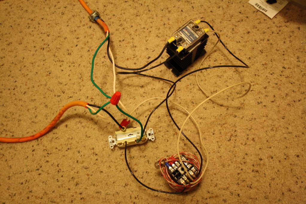
Currently I have a Auber PID, SSR, and heating element for RIMS wired with a power coming in and the element coming in.

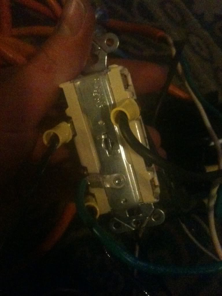
I want to wire those things incorporating a GFCI outlet for the March pump and element, and a switch for the pump.

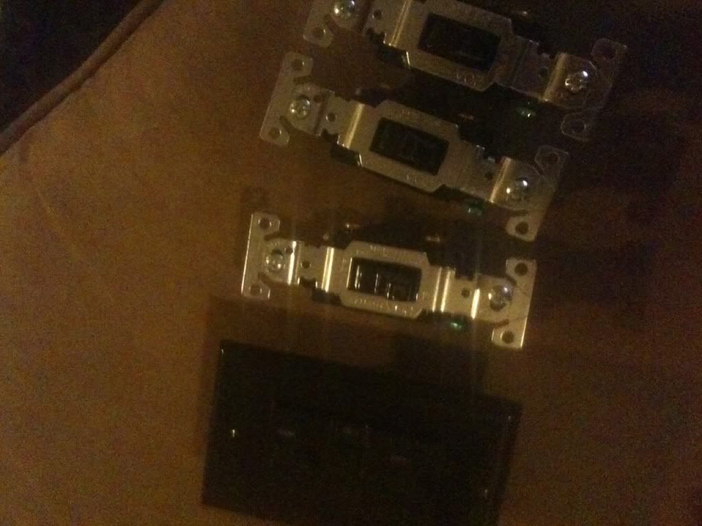
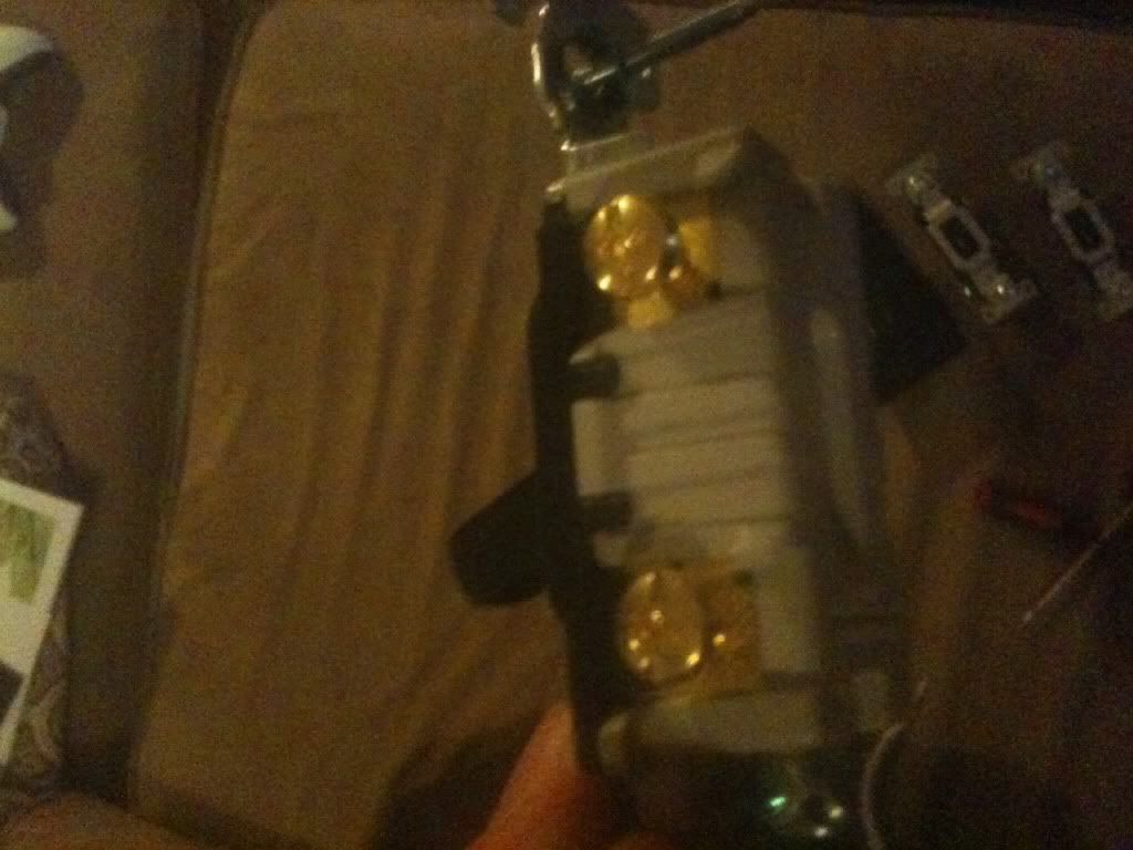
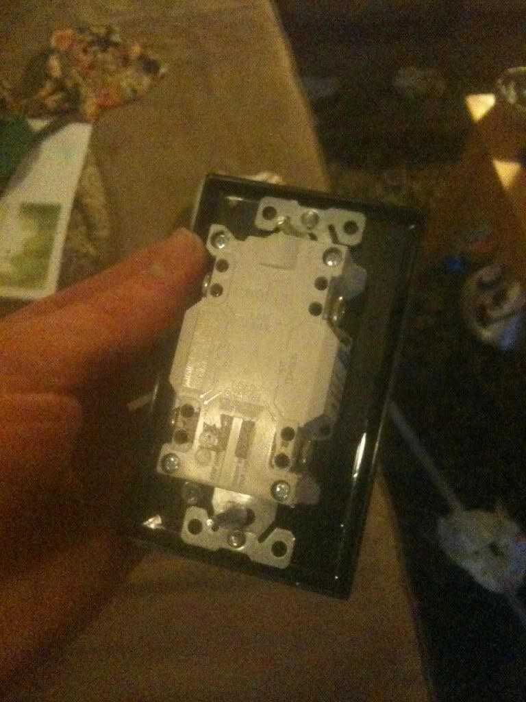
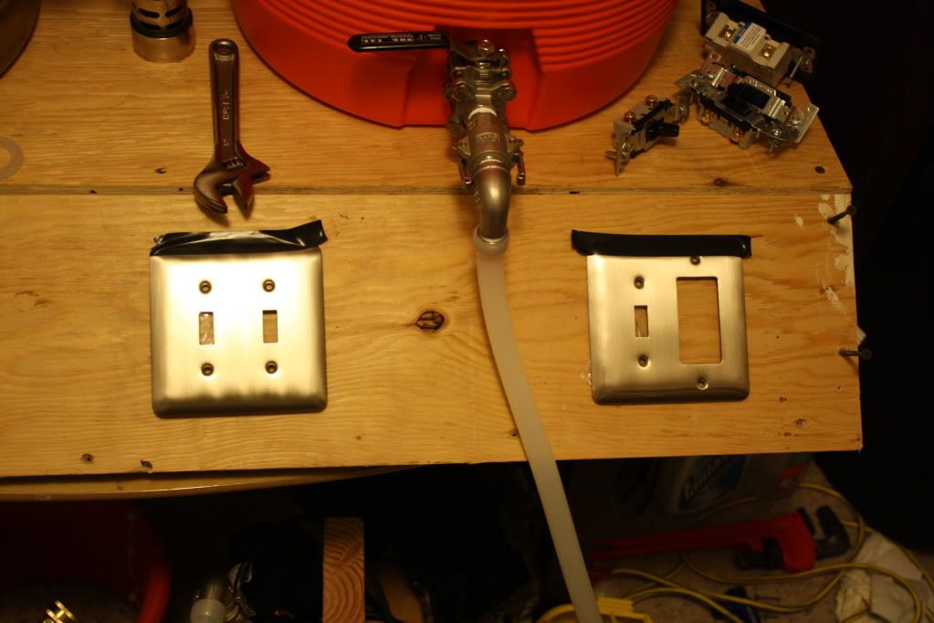
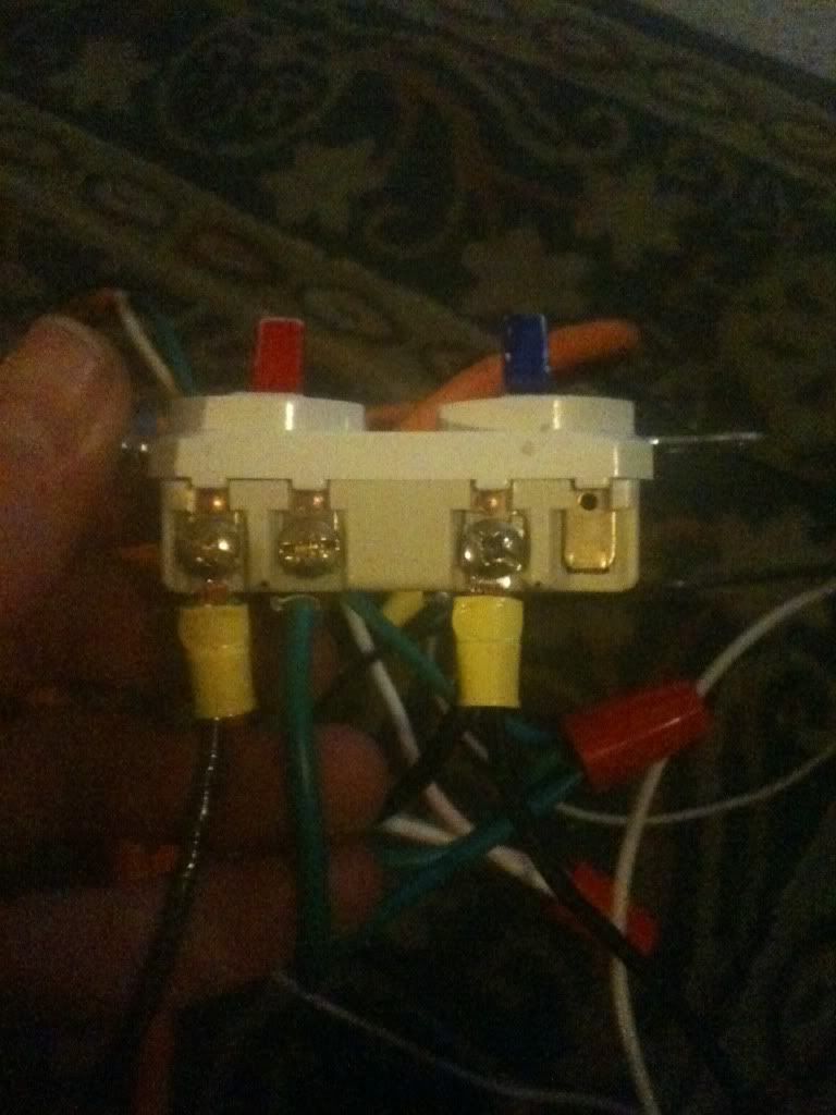
Here are some pics to help hopefully...
This is the current wiring:
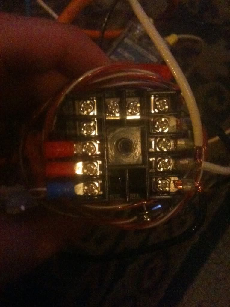
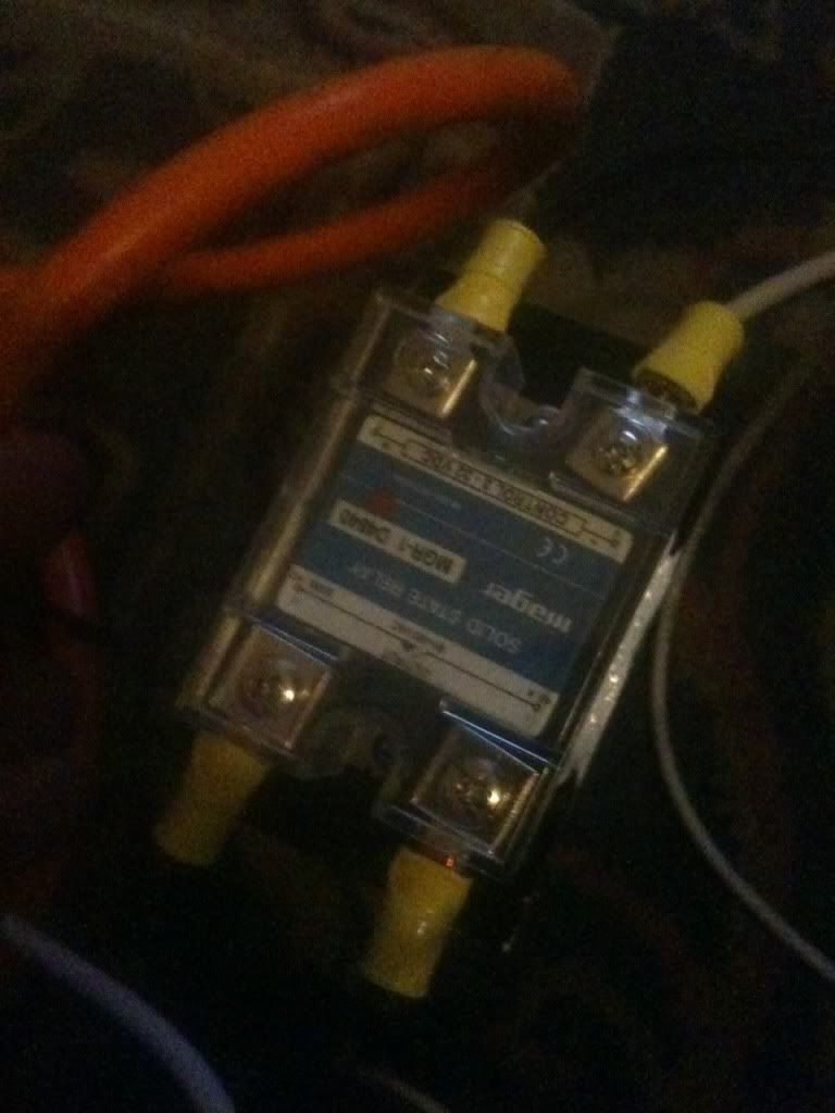
photo4.jpg

photo3-1.jpg

photo2-1.jpg

photo1-1.jpg
 
And I want to add this outlet and replace that double switch with these single switches, adding another one for the pump.
photo1.jpg

photo2.jpg

photo3.jpg


I am not sure if I can run them together on the outlet without popping a breaker, I will have to wait and see. Not sure what wattage the element is because I bought it assembled over a year ago.

Let me know if I can answer any questions to help, probably not doing the best explaining seeing that its 4 a.m. and I have been working on the rig all day...so close cant wait to fire it up!
 
I am assuming you are only using 110V.
What do the current switches control?

Do you want the GFCI to interrupt the entire system or just the pump?
If you want the entire system the the GFCI outlet needs to be rated for 20amps.

Once I know what you have, I and others might be able to assist you.

Regards,
Andrew
 
Thank you for the replies...

I realize I was vague in the op. and after thinking about it a lot and reading some more, my original plan wouldn't have worked anyway. So I have a new pic that should make thinks a lot clearer of what I have now.
IMG_3239.jpg

The the orange extension cord coming in from the top would be coming from the male end of the power cord, and the other end going to the heating element.

I want to take out the double switch shown, and replace it with two independent switches so I can mount in the panel. Those control the element and the pid controller. Then add the GCI outlet and another switch to turn it off and on for the pump.
I am not sure yet if I can run the two together(element and pump). It sounds like it would be pushing it. So any solutions to that would also be appreciated. Maybe run another power cord for the outlet and pump to plug in to a different leg of the house? Im obviously open to suggestions...

This is something like how it will be mounted if that helps also...
IMG_3241.jpg

From left to right will be PID, Element, Pump(with outlet for it)

Thanks guys!!!
 
We need more information. What's the rating on the element you're using? What's the rating on the circuit you are using to supply power to the element? From that we can determine how close you are to going over what you can supply.

Put together a drawing of what you are trying to accomplish. Take a picture of that drawing an post it here.

Don't worry about whether or not you can change what you have to what you want. Of course you can. It's simply a matter of stating/knowing what you want to do then fabricate that.
 
I understand what you have.
Couple of more questions.
1. What guage is the extension cord? Should be 12 (20amp) or 14 (15 amp) gauge.
2. Look at the element, it should have the wattage stamped on the plastic end.
3. Are you pluging this all into a wall outlet with GFCI? Is it 15 or 20 amps rated?
4. What is the circuit breaker amp rating?

If the element is 1500 watt it will pull 12.5 amps at 120v and the 2000 watt pulls 17 amps.
If you have a 20amp circuit in theory you should be able to accomplish this.

I have a circuit diagram that shows how everything should go together for the type of setup you are trying to accomplish. I will edit it for your setup once I have the above information.

Andrew
 
The problem is that I bought the rims unit already assembled like a year and a half ago. I can try and send the seller a pm but it's prob a long shot.

So I am not sure what gauge the cord is but I am assuming it's 12 gauge from how it looks and that is was meant to run the element.

The element itself appears to be sealed in a PVC cap type situation so I can't read the wattage off of it. I will take a picture and post.

The gfci that I want to install is rated to 20 amps.

I am not sure what the circuit breaker rating is, I am at work so will have to check it out later.

I will try to get as much info as possible to help out...
Thanks again!
 
Option,

I'm in Denver this week on business.
If you want, you can swing by my hotel in Lonetree.
PM me if this works for you, otherwise I can post my diagram.

Later,
Andrew
 

Latest posts

Back
Top