• Please visit and share your knowledge at our sister communities:
  • If you have not, please join our official Homebrewing Facebook Group!

    Homebrewing Facebook Group

Wiring Diagram Review

Homebrew Talk

Help Support Homebrew Talk:

This site may earn a commission from merchant affiliate links, including eBay, Amazon, and others.

streloc78

Member
Joined
Dec 30, 2014
Messages
5
Reaction score
0
Hello,

I am building a PID control box with SSR and SSRV. I took one of the P-J Diagrams and modified a bit. Could some please take a look at it and review it? I am not an electrician, Thank you.

Here is my set up, I have NEMA 6-20 with 20 amps in my apartment, I would like to power and control 3750 w 240V BoilCoil. I test it with amp/volt meter and it gave me 210V. By my calculations it should be fine.

Changes that I have made to the diagram:

1. Use of GFCI breakers instead of regular.
2. Additional line for ALARM BUZZER with shut off switch. (Just to wake me up when certain temperature has been reached).
3.Addition of SSRV form power to the element control while boiling.

HAPPY HOLIDAYS to all!
Thank You Very Much!
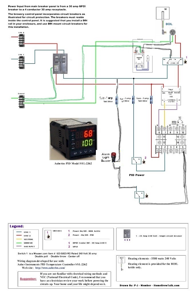
Modified P-J diagram.jpg
 
Can´t read it. My eyes aren't what they used to be anymore!
Try it. Keep a fire extinguisher at hand! :p
 
You need a jumper wire between PID terminals 4 and 1 to make buzzer works.
You can also simplify your controller a bit if you connect wire going from buzzer to fuse to PID terminal 2 instead. Buzzer circuit will be proteted by PID fuses and you can get rid of separate fuse for buzzer.

Otherwise everything looks OK.
 
What are the current and voltage ratings of switch #1? Most people use contactors for this switching function, as they have better current/voltage interrupting capability and longer lifetimes due to heavier duty contacts.

What's with the ground wires going to the SSVR? Not sure what they are supposed to be doing.

Brew on :mug:
 
The switch 1 has 20 amp 250v rating. Should I use contactor instead?

As far as SSRV I thought it had to be grounded as all elements... if it is not the case, I will erase the connection.

I will make jumper on PID between 5-2


Thank you very much Gents for your help!
 
The switch 1 has 20 amp 250v rating. Should I use contactor instead?

As far as SSRV I thought it had to be grounded as all elements... if it is not the case, I will erase the connection.

I will make jumper on PID between 5-2


Thank you very much Gents for your help!

The switch appears to have an appropriate rating, but only just enough.

Yes, the heat spreader (metal chunk on back) should be grounded. This can be accomplished by bolting to a metal panel box that is grounded (make sure paint is scraped away at contact point for low resistance) or bolting to a heat sink which is in turn bolted to the grounded panel (clean contact points between all pieces required.) If your controls are in a non-conductive box, then a wire from the ground bus to the SSVR heat spreader is in order.

I asked because it looked to me like one of the ground wires was connected to one of the SSVR termials, which would be a very bad idea, and the SSR did not show explicit grounding.

Brew on :mug:
 
Thank you very much for looking at it.
I didn't think about box grounding. I am going to have to wire everything back to ground anyway, my box is de electric.

...... HAPPY NEW YEAR..... Ordered the parts today so next year with a new brewing set up......:ban::ban::ban:
 
From paper to Results:

Last night conducted first heat test.

The BrewCoil performed flawlessly (I have a 240v for 10 Gal 3700 W), four gallons of water from 80 F to 180 in around 5 minutes.
The http://greatbreweh.com/Beer_Pump.html pump is fast enough and works well, Please the picture 1/2 inch fittings everywhere and at full blast.
The box: I had to make a few modifications to the diagram. First I removed the GFCI backers (they were really big and didn't fit). I change them over to the inline GFCI interrupter cheaper and more stream lined: http://www.cableorganizer.com/trc/gfci-elci-attachables.html?gcssku=TRC-25000-016 the 240/20 A version.
Second thing is alarm, oh well it is useless ... at least from what I have come up with. The alarm could only be set via entering the code and etc, it will not take the PV as an alarm trigger, unless I am wrong.

Third, is the SSRV the knob power regulator. PID does this in manual mode. :confused:

Otherwise, everything else works great. Will need to have some loose nuts tightened (leaks :mad:) and begin brewing.

20150122_205733[1].jpg


20150122_205723[1].jpg


20150123_071845[1].jpg
 
Back
Top