Wiring Diagram Double Check

Homebrew Talk - Beer, Wine, Mead, & Cider Brewing Discussion Forum

Help Support Homebrew Talk - Beer, Wine, Mead, & Cider Brewing Discussion Forum:

This site may earn a commission from merchant affiliate links, including eBay, Amazon, and others.
Was your element plugged in when you tested pin 2 of the SSR? I'm guessing it was not. According to Crydom (a major manufacturer of SSR's) you cannot properly test an SSR with a voltmeter. To check the SSR output you should have the power on and the element plugged in (obviously the element should be in a large volume of water.)


The control outputs of the PID and DSPR1 are floating w.r.t ground, so trying to measure voltage between them and ground won't give good data. What you want to do is:
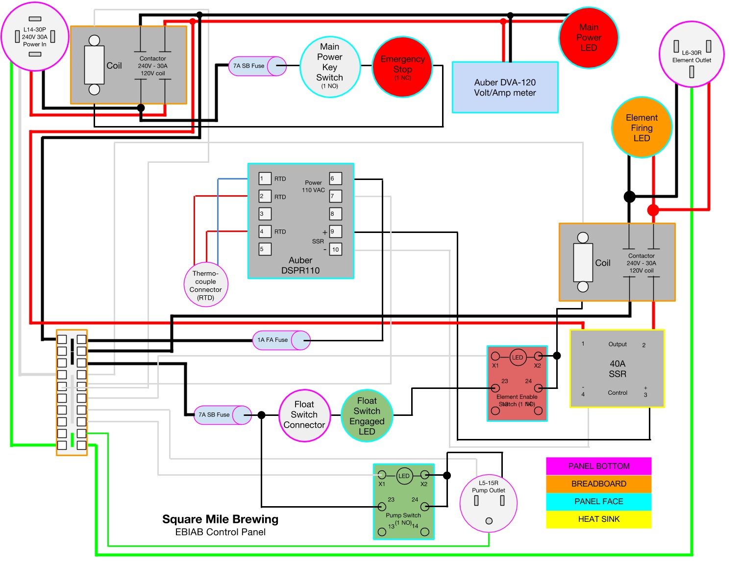
  1. Unplug the element
  2. Put the control selector switch in the DSPR1 position
  3. Set the DSPR1 to 100% output
  4. Measure the voltage between pins 3 & 4 of the SSR with the voltmeter on a DC scale


I would do the test on pins 3 & 4 before doing the hot element test.


Brew on :mug:


Just tested and got 8 VDC across the SSR. Does that sound about right?
 
Just tested and got 8 VDC across the SSR. Does that sound about right?

8V is plenty to trigger the SSR. Did you check that the polarity is correct? Does the light on the SSR come on when you have 8V on the inputs?

Brew on :mug:
 
As I'm getting closer to actually starting this build I've got a question about how switch block stacking works on the Auber SW3, three position maintained.

To refresh your memories, I'm planning on using it to switch between the SYL-2532 and DSPR1 operating a single SSR to the element. If I use four NO blocks, one for each positive and neutral wire coming off the PIDs, should I stack them like this:

Block 1 - 2532 +
Block 2 - 2532 -
Block 3 - DSPR1 +
Block 4 - DSPR1 -

Leading off of the switch blocks can I tie together the two neutrals and the two positives since there's only one terminal for each on the SSR?

I've tried searching around on the Auber site and this forum and can't find a clear answer.
 
Ignoring my last post in this thread (from way back in February), things have changed a bit. I'm now building this panel with only the DSPR-110 (I bought it before the 120 was out) instead of switching between a PID and a boil controller. I've actually got the box cut, painted and the components are all dry-fit installed. I'm about ready to get started wiring everything (full build thread later) but before I start cutting wires and hooking things up I just wanted to get a double check on my amateur wiring diagram.

YZ5vA6I.jpg
 
Your float switch circuit won't work as drawn. The "float switch closed" LED needs to be wired between the downstream hot from the float switch and neutral (just like the LED's in the lighted switches.) Also, what are you using for a float switch? Many float switches aren't rated for 120VAC, so you need to make sure yours can handle 120V, and is also rated for about 250˚F service. For safety, I would put a 1A fuse before the float switch connector, although the GFCI on the main power feed should take care of any short in the float switch circuit. A more safety conscious design would use low voltage to the float switch, and the float switch driving a relay to switch the 120V.

The fuse for the main power contactor coil circuit should be reduced to 1A (from 7A), as the contactor coils take less than 0.1A.

You don't show how the ammeter sensor portion of the volt/ammeter is wired.

Brew on :mug:

I'm using this float switch from Auber.

Here's an updated diagram:

pub


  • I added neutral lines to 3 LED lights: Main Power, Element Firing and Float Switch Engaged.
  • Changed wiring to Main Power and Element Firing LEDs to only take 1 hot line instead of both.
  • Changed fuse before main power switch to 1A FA.
  • Connected the float switch to the 1A FA fuse line that goes to the DSPR-110.
  • Added ammeter coil to diagram, looped around the two hot lines from the contactor.
 
I also didn't thank you for the feedback in the last post.

You mentioned having the float switch trigger a relay. Would this one do the trick?

EDIT - Added the mini relay:

pub


EDIT 2 - Looks like you embed a Google Doc and update it, the changes appear, so that's why the diagrams are the same in the last two posts.
 
I've been on the Auber forum a little bit trying to figure out the proper wiring for the DVA-120 Volt/Amp meter. The voltage input on the board can't accept 10 gauge wire. I have connectors that will allow me to barely get it in there, but others were suggesting a different wiring. Above the voltage input would just connect to the side of the contactor with 14 gauge wire that isn't stepped-down by a fuse. This doesn't strike me as correct. Can anyone verify that what you see above is OK?

Also, side note: The Google Drawing above is embedded and updated as I make changes, it's not a static image.

Thanks!
 
It wouldn't hurt to fuse the voltage wires to the DVA, but I don't think it's necessary. Personally, I would use 20-22AWG wire for that as the DVA will draw almost 0 current. And in the case of fine wire, the wire itself will fuse in the event of a dead short. If your enclosure is a metal box, then there is little risk involved (as long as you follow all the other safety rules.)

Brew on :mug:

Awesome! Thank you. The box is metal so I should be all good to go. The box is fully grounded and everything else is wired as you see it above.

This is the last bit of wiring I needed to figure out, so my full controller build thread will be coming soon.
 
Back
Top