Wiring a Dual Ball Float Switch

Homebrew Talk - Beer, Wine, Mead, & Cider Brewing Discussion Forum

Help Support Homebrew Talk - Beer, Wine, Mead, & Cider Brewing Discussion Forum:

This site may earn a commission from merchant affiliate links, including eBay, Amazon, and others.

HungusBrews

Well-Known Member
Joined
Jun 25, 2008
Messages
140
Reaction score
4
Location
Roxbury
I am looking for advice on how I would wire up this dual ball float switch to control a march pump.

I currently use a BCS to control SSR's for my ferm chambers and fire a burner on my HLT so I have a pretty good understanding of basic SSR wiring. What I can't seem to wrap my head around is wiring a NC and a NO switch TOGETHER to turn a pump on and off. Do I use a DPDT relay? A DPST relay? I can use the 5V signal from the BCS as the power source.

This will be used in a grant that I am building and installed in the bottom. So the pump should turn on when the grant is full meaning the bottom and top floats are up. Then it should shut of when the grant is near empty when and both floats are down.

Any advice would be much appreciated! A link to a relay that would work would be even better. Once I have one in my hand I am sure I can figure it out. :mug:
 
Last edited by a moderator:
Well, there are two ways to do this: hardware or software. You really don't need two switches as you could use just one switch and rely on the hysteresis of the switch to turn the pump on and off. You could direct wire OR wire through the BCS if you wanted to control and montor via the BCS. In this case, when the switch turns on, it powers the pump, and when the level drops just enough, the pump turns off again. Set the level by setting the height of the switch, but you cannot set the ON/OFF difference as that would be controlled by the switch hysteresis. Obviously a wider grant extends the time the pump runs for a given volume reduction.

For two switches, it could be done in hardware or software... again depending on how you want to monitor and control in the BCS.

In software, you wire both switches as inputs to the BCS. I assume they are two wire, meaning they are NO hardware switches. One pole would go to +5V and the other to the respective digital inputs (DINs). This would obviously occupy two inputs. In the logic, You could either run this in a state or ladder logic. In the state method, you would use two states, which exit into each other. For example: for state 1, it would have the pump output OFF and an exit condition when switch 1 (top switch) turns on to start state 2. For state 2, it would have the pump output ON and an exit condition that when switch 2 (bottom switch) turns off to start state 1. Make sense? You could also handle this in ladder logic as I noted, but this would be always running then unless you qualify it with a register assertion.

In hardware, you could really just power the pump via a relay which has a coil voltage that matches the pump's. I would use a mechanical relay, not an SSR. On the relay contact (switch) side, it feeds the LINE to the pump (other end of pump tied to NEUTRAL). One end of the relay coil is tied to NEUTRAL. The top float switch has one pole tied to LINE. The top switch's other pole connects to the relay coil LINE side through the bottom switch. You also tie the output of the relay contacts pump side to the other pole of the top switch. This creates a latching relay. This way, when the liquid rises high, the bottom switch is closed, and the top switch is open, so the pump does not run. When the liquid reaches the top switch, it closes, causing the relay to power and the pump to run. When the liquid drops below the top switch and it turns off, the relay remains latched by its own output power. Now when the liquid level gets below the bottom relay, it breaks the latch, causing the relay to open and the pump to stop. Make sense? This is tricky to explain without a schematic, so say PLEASE if you want one.

-BD
 
Thanks BrunDog!

The hardware option is more along the lines of what I was thinking. Thank you for taking the time to write such a detailed description. Wiring it for BCS control is tempting but I think having it work in the background with hardware is more bomb proof. I thought I would need the low voltage outs from the BCS which is why I mentioned it. I appears that if I use a mechanical relay I do not need to include the BCS.

I found this one on amazon which I think would get the job done. What do you think?

Also...I am going to officially say PLEASE can you hook me up with a wiring diagram if its not too much trouble? Even if its just a photo of a napkin sketch. Appreciate all your help!
 
Last edited by a moderator:
That relay will work. You only need a SPST (single pole and throw) but that's ok, you just use the NO (normally open) pole. Here is a quick schematic I sketched up as I wait for my plane to blast off.

Oh, now that I drafted this, I realize I should have reversed the neutral and line terminals. Doing so would make the system slightly safer as the line voltage wouldn't be routed out in the open - it would be contained to the local relay wiring. So you can just reverse these two in practice.
View attachment ImageUploadedByHome Brew1436555235.950478.jpg

-BD
 
Thanks BD! Really appreciate it. Ordering all my parts now and will post back once I have it all wired up. Cheers!
 
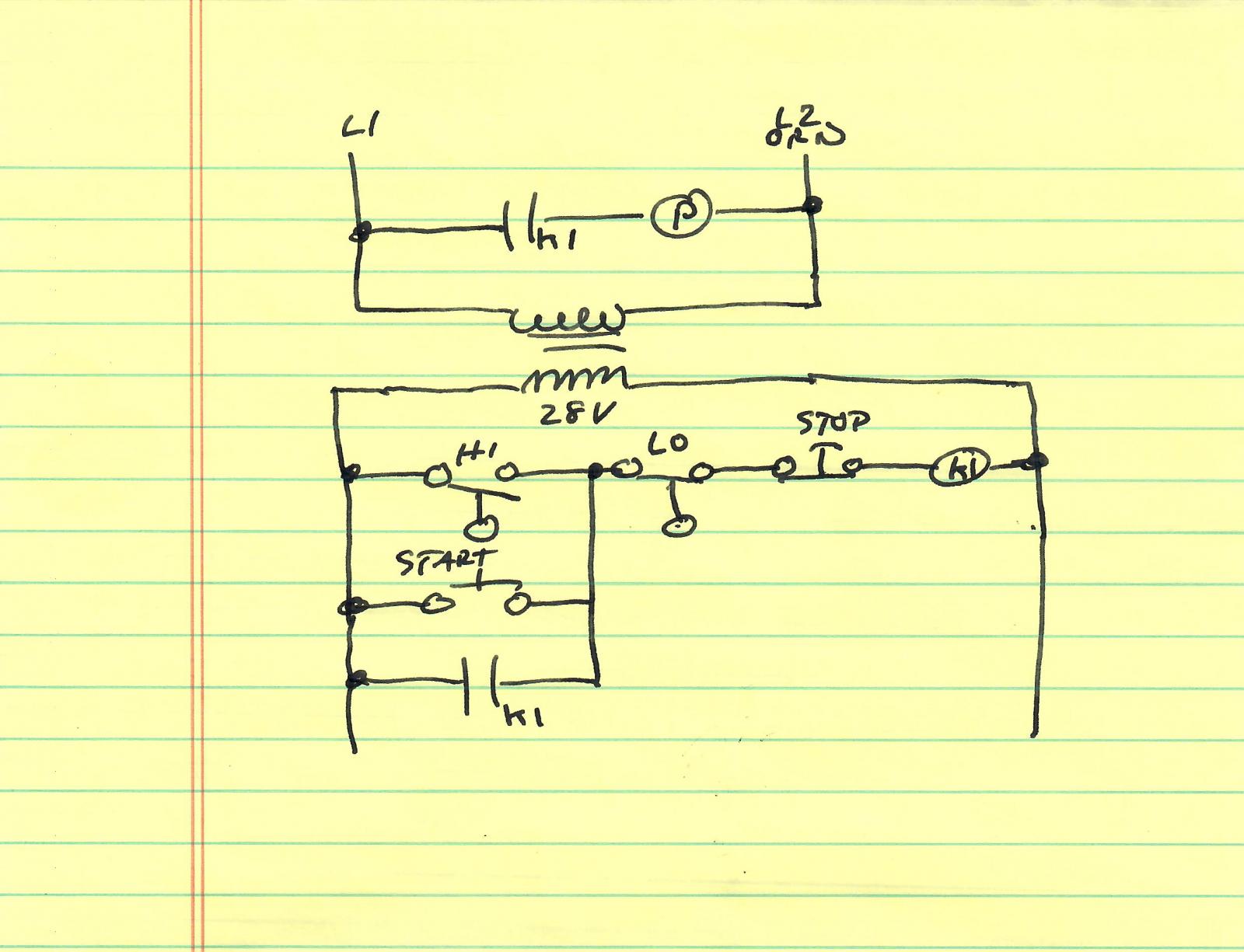
While the proposed scheme will work you might want to consider adding the following features as shown in the attached sketch.

1. Use a 28 V control transformer and put a fuse in series with it (not shown in sketch). The switches are immersed in liquid and the idea of running line voltage for control purposes makes me nervous. Be sure to select a 28 V relay if you do this. If you decide not to then get a line voltage relay. The fuse is still a good idea.

2. Add manual start and stop pushbuttons as shown. These will enable you to start the pump before the grant is completely full if you want to and, more importantly, will allow you to stop it if a hose comes off or some other unforseen event occurs while the grant is still partly full. The stop button is, IMO, much more important than the start. Note that this requires a 2 pole relay with one contact to control the pump and the other to latch the relay when either the start button is pressed or the hi float switch closes.

Floats.jpg
 
A little insight before you get too far along.

These appear to be the same 'reed' switch floats I use at work.

You chose the N.C/N.O. option by removing the float and flipping it.

As an example:
The top float.
One job will have a pump come on when the level rises. N.O. changing to Closed
Another job would have a heater disabled if the level falls. N.C. changing to Open

All it takes is to flip the float, (Float has a ring magnet inside)

Find a float setup that has NPT threads. We control pump/heater by length of threaded support pipe.

'da Kid
 
AJ is correct about the lower voltage. This is the reason I said to switch the line/neutral in my sketch as you can keep high voltage out of your liquid. I would also suggest making sure there is a liquid tight sleeve over the wiring if possible.

There are also other sensors which would be an improvement to having sensors in your liquid. You could use capacitive sensors on the outside which detect the liquid level inside. These need to be pretty good quality sensors to "feel" through the SS grant walls. Alternatively you could put in a short sight glass and use opto or capacitive sight glass sensors, thought this is less practical due to the number of parts and mods required. Both of these approaches will be much more cost that that float assembly, though I expect the float design will get gunked up pretty quickly. Let us know if you need more help.

-BD
 
You could use capacitive sensors on the outside which detect the liquid level inside. These need to be pretty good quality sensors to "feel" through the SS grant walls.
I don't think conventional capacitive sensing is going to work through conductive steel very well. There is, however, a technology using ultra sound that does. It sounds ultra expensive!
 
I don't think conventional capacitive sensing is going to work through conductive steel very well. There is, however, a technology using ultra sound that does. It sounds ultra expensive!


You are probably correct. I was thinking of an application I did a while back but now recall the vessel being of thin walled aluminum. There are capacitive sensors which are designed for such food safe applications but would require a small hole in the grant for mounting. Still not cheap but cheaper than US and infinitely more reliable. I think the resistive volume tapes are intriguing but the temp ceiling limits us.

-BD
 
As aluminum is conductive too I don't see how they would work with that either. My understanding is that these sensors are used on SS vessels but that a dielectric window is installed (glass I guess) for the sensor. This, of course, compromises vessel integrity somewhat and adds to cost.
 
Thanks for all the advice everyone! AJ, you made some excellent points about incorporating an additional on/off feature and moving to a lower voltage does make a lot of sense from a safety standpoint.

With these suggestions in mind, I think controlling the hi/low switch with the BCS sounds like a better path. I eventually plan on expanding the BCS to control more of my hot side so why not this? As BD mentioned I would simply need to wire one pole of each switch to the +5vdc and then the other poles to an independent DIN. The pump would be controlled with an SSR. I could also wire the pump through an HOA switch to run it without the grant switches. Where I will get tripped up now is in the programming.

In the state method, you would use two states, which exit into each other. For example: for state 1, it would have the pump output OFF and an exit condition when switch 1 (top switch) turns on to start state 2. For state 2, it would have the pump output ON and an exit condition that when switch 2 (bottom switch) turns off to start state 1. Make sense? You could also handle this in ladder logic as I noted, but this would be always running then unless you qualify it with a register assertion.-BD

When I am mashing, I have an ignition sequence running in one state to fire on/off my HLT burner. When I need to change temps I simply move to a new state. Currently I recirculate my mash by turning the pumps on/off manually. If I use the state method to cycle between switches as BD mentioned above, how will that affect my ignition sequence?

I think I may need to go to ladder logic, which I have zero experience with.

Thanks for everyone's help here!
 
Remember that capacitive sensors work on variations of conductive and dielectric materials.

On the BCS, you can run multiple processes concurrently. In each process, only one state can run at a time. Therefore, if needed you would put the states to control the pump for your grant in a discrete or different process.

-BD
 
Remember that capacitive sensors work on variations of conductive and dielectric materials.
They work on variations in the properties of materials which are in the capacitor's electric field. If you put a piece of conductive material between the capacitors electrodes and the thing you are trying to detect you will detect the conductive material but not anything on the other side as the electric field will not reach that thing being confined to the conductor. When capacitive sensors are used with metal tanks a window or well of dielectric material must be used.
 
Some of this is well beyond my pay grade, but how suitable for this application is a hydrostatic pressure level sensor? I used to use a plastic one in an aquarium application, and it worked great for many years. No moving parts in contact with the liquid, so nothing to fail there.
 
On the BCS, you can run multiple processes concurrently. In each process, only one state can run at a time. Therefore, if needed you would put the states to control the pump for your grant in a discrete or different process.

Makes total sense. Any suggestions on running the actions I described within one state though? I already have half of my processes taken up with Ferm control. I realize I can save and upload new processes as needed but it would be nice to avoid that.
 
@jeffmeh: I think this is a good idea but for this application the grant will not have much height and the BCS controller cannot directly measure analog signals. It would need interfacing hardware such as an Arduino.

@HB: You could take one existing process and add the pump on/off to two states which are otherwise duplicated. Or, alternatively, since you are out of states, just do this in ladder. You can assert a register and use that as a requirement in the ladder logic also. A few lines of ladder should be all that is needed I think.

-BD
 
While the 2 state (BCS) solution will work for this, I suggest finding a way to use a dedicated process and even expand beyond two states.

Here's my reason... What happens when the first float is triggered but the second one is not? This is going to happen at least once during your run off at the end and you'll end up with collected wort that doesn't get transferred to the BK. It could however end up happening more than once if you are getting a stuck or slow sparge. I'd suggest that when the first float is triggered that you then set a timer that should allow for sufficient time for the wort to reach the second float and if it doesn't within the set time, that you either pump out the remaining wort or possibly set an alarm so that you are made aware of the situation. Add more states to handle all possible situations.

How many processes are you using for fermentation? You might be able to combine some of the functions there so you're not using multiple processes. I use a single fermentation process that handles two fermenters at different temperatures, maintains the glycol bath temp and also has states for crash cooling.
 
How many processes are you using for fermentation? You might be able to combine some of the functions there so you're not using multiple processes. I use a single fermentation process that handles two fermenters at different temperatures, maintains the glycol bath temp and also has states for crash cooling.

Right now I have 4 processes for fermentation loaded onto my BCS. One for ales, one for lagers, and for two different freezers with heaters inside. My lager processes have a few more states than ale which is why I had kept them separate. You have definitely sparked my interest as to how the heck you maintain two fermentors in one process!

You make a great point on running a dedicated process for the grant.
 

Latest posts

Back
Top