• Please visit and share your knowledge at our sister communities:
  • If you have not, please join our official Homebrewing Facebook Group!

    Homebrewing Facebook Group

Wire elements direct to switches, PID/relay, or outlets?

Homebrew Talk

Help Support Homebrew Talk:

This site may earn a commission from merchant affiliate links, including eBay, Amazon, and others.

WhiteArmadilloBrewing

Well-Known Member
Joined
Jul 28, 2017
Messages
81
Reaction score
5
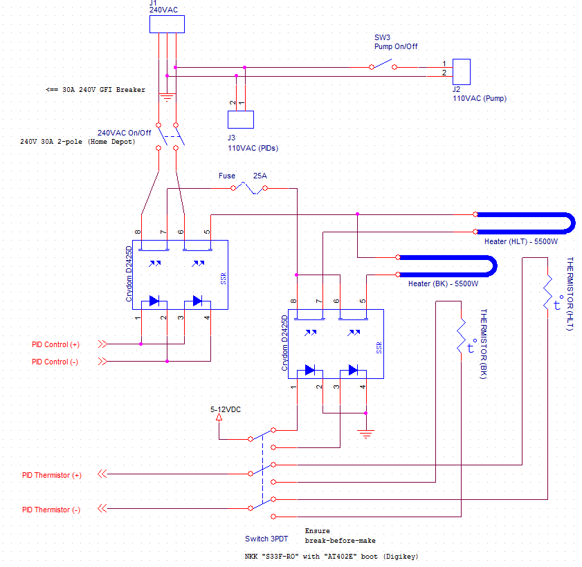
I'm trying to finish up my control panel build and had a question on wiring up my heating elements. I have two 240v elements in the BK and Mash Tun as well as a 120v RIMS. My question is this: before I install additional switches to power these is there any reason not to just wire them directly with my PID so that they are regulated by the PID and not manually by me/my switch?

I've seen a number of builds where people hardwire their elements to plugs and run them through a receptacle as well but am unsure what the easiest/most effective solution is.
 
What PID are you using? Does your PID have an internal relay? If so is it rated for the amps that your wanted to hook it up to? If so then you can do that. I'm guessing it doesn't.

The idea is that the PID is just a mini specialized computer that sends out a low voltage/ low amp DC signal for on off. You then hook this signal up to a relay (Solid state relay or SSR) that will in turn switch the 120/240 v on and off accordingly. You wire your heating elements to this relay, not your PID. You would use a switch or contactor in series as a manual cut off for reasons including but not limited to should the SSR fail.

... Maybe I'm misunderstanding the question.
 
Sorry, I should've provided a few additional details. I will run (2) Auber EZBoils to control RIMS Mash and BK. In between the EZBoil and the elements there will be contactors, fuses, circuit breakers, and SSRS. What I'm asking is if I should wire the elements to a simple manual selector switch and control the on/off manually or wire the elements through that series of safeguards to be controlled (on/off/cycled) by the PID?
 
Sorry, I should've provided a few additional details. I will run (2) Auber EZBoils to control RIMS Mash and BK. In between the EZBoil and the elements there will be contactors, fuses, circuit breakers, and SSRS. What I'm asking is if I should wire the elements to a simple manual selector switch and control the on/off manually or wire the elements through that series of safeguards to be controlled (on/off/cycled) by the PID?
the manual switch(s)/controls your describing are only used for four reasons.
1] the power doesnt support firing of both elements at the same time (30 amp service with say 2 5500w elements) so a 3 way switch is installed to allow power to only flow through one at a time or none (still controlled by the pid though)

2] The person has a pid without manual or pwm power control and doesnt realize they can accomplish 100% on at boiling by setting the pid to a temp higher than 212 to prevent the pid from turning on and off at akward timings and stopping and restarting the boil.

3) Bling, Some people are impressed by more complicated looking controls and feel more lights and switches makes the panel "cooler" many people with pids feel switching to auto and manual mode is too hard (depends on the pid but ive been told the auber ones are more work to do this than the mypins im used to) so they install a manual dial control on top of the pid that already has this function. This is totally not needed with an ezboil controller.
others just arent really sure how things will work or what might be beneficaial or not so they add things and then realise they dont need them.

4] some people like to monitor temps and have the ability for things like timers and such to run but with actual heating disabled.
 
Keep in mind the pid doesnt control the contactors which kill power to both legs of element power.. A manual switch does that. The pid only controls half the power on one ssr to make the circuit incomplete. if you are monkeying around unplugging something or water spills on it there is still potential for electrocution in the unlikely event the gfci doesnt trip (or while it does).
 
Makes sense about the reasoning and I'll keep the two I installed currently to power on/off my two pumps since those will be manually controlled during the brew.

Clarification question then: so the reason to wire a manual switch to the contactors would be as a fail safe option then?
 
Sorry, I should've provided a few additional details. I will run (2) Auber EZBoils to control RIMS Mash and BK. In between the EZBoil and the elements there will be contactors, fuses, circuit breakers, and SSRS. What I'm asking is if I should wire the elements to a simple manual selector switch and control the on/off manually or wire the elements through that series of safeguards to be controlled (on/off/cycled) by the PID?

I use PIDs to control two separate elements. Control signals from the PIDs drive SSRs. I use a manual DPST 240V 30A switch to turn the power off to all four SSRs. That switch is basically my Estop. No contactors in my system.

BTW, I bought that switch at Home Depot, right off the shelf. In fact, I have two of them: one on my control panel, and an identical one (with a wet location cover) on the wall where the panel plugs in.
 
Makes sense about the reasoning and I'll keep the two I installed currently to power on/off my two pumps since those will be manually controlled during the brew.

Clarification question then: so the reason to wire a manual switch to the contactors would be as a fail safe option then?
thats one reason.
the other is because 240v is made up of 2 wires with 120v each going to the element along with a ground. the ssr connected to the pid only turns one of the 120v wires on and off so to speak. you still have 120v going to the element and plugs at all times unless theres a contactor to switch voltage on and off at both wires. also when ssrs fail they always get stuck in the on position.

the manual switch of some kind is what normally turns the contactors on and off unless you want all of your elements to always be on if you dont go into each pid and change the settings to turn them off each time.. (you dont want to do this its much more work) think of contactors as powerful switches that you can control from a weaker switch mounted on the control panel face, thats all.
 
Last edited:
I use PIDs to control two separate elements. Control signals from the PIDs drive SSRs. I use a manual DPST 240V 30A switch to turn the power off to all four SSRs. That switch is basically my Estop. No contactors in my system.

BTW, I bought that switch at Home Depot, right off the shelf. In fact, I have two of them: one on my control panel, and an identical one (with a wet location cover) on the wall where the panel plugs in.
I almost went this route on my latest panel. good alternative. So is the more expensive 2 pole ssrs, or dual ssrs but in the end less heat and heatsink space cause the contactors to win.
 
Last edited:
I think this is the route I will go as I already have a few extra DPST Switches available to use. I'll have to check my SSRs to see if they are 2 pole or not?

@passedpawn - do you have your wiring diagram I could take a look at?
 
What would you use the DPST switches to control? You could wire them to interrupt ssr control power like passedpawn or control a contactor but unless they are 25amps or more you dont want to control the element power directly with them. just mentioning this because standard wall switches are often only 15 amps and most 22mm control panel type switches are 10amps.If your ssr only has 4 screw terminals its only single pole. They are far more common.
 
I mistyped -- I have these switches (https://cdn.automationdirect.com/static/specs/cents22mmselect.pdf) not a DPST.

I'm trying to figure out the best wire up my elements?! so that they are ultimately controlled by my EZBoils to regulate RIMS temp and BK. I have one element that I plan on manually controlling with a switch to bring my strike water up to temp. Then I would like the EZBoil to control the element within my RIMS tube to regulate.
 
whats going to stop the element when it reaches strike temp? are you going to just watch it and hope to catch it? how many elements total 3? HLT, BK and rims? if so you can just use the same controller to control both the bk and HLT you can switch plugs and temp probes or just us a cheaper mypin pid for the hlt where it would be better suited to the task. lots of options. those switches you have wont work for direct control they are only 10amp as youve read.
 
whats going to stop the element when it reaches strike temp? are you going to just watch it and hope to catch it? how many elements total 3? HLT, BK and rims? if so you can just use the same controller to control both the bk and HLT you can switch plugs and temp probes or just us a cheaper mypin pid for the hlt where it would be better suited to the task. lots of options. those switches you have wont work for direct control they are only 10amp as youve read.

I have a digital thermocouple in the HLT and, yes, was going to switch off the element, mash in, fire up RIMS + Pump from there.

3 total elements. 4500w in HLT, 5500ULWD in BK, and 1500w in RIMS.
 
whats going to stop the element when it reaches strike temp? are you going to just watch it and hope to catch it? how many elements total 3? HLT, BK and rims? if so you can just use the same controller to control both the bk and HLT you can switch plugs and temp probes or just us a cheaper mypin pid for the hlt where it would be better suited to the task. lots of options. those switches you have wont work for direct control they are only 10amp as youve read.

Damn, just noticed that with the switches. Better now than when I have everything wired up. I bought them initially to be my on/off switches for my pumps and they came as a lot of (4), was hoping I could use them for something else but clearly not. I suppose the question is now: what switch options are available for handling 30a to control the SSR's and elements?
 
I think this is the route I will go as I already have a few extra DPST Switches available to use. I'll have to check my SSRs to see if they are 2 pole or not?

@passedpawn - do you have your wiring diagram I could take a look at?

Yea, I have it around here somewhere. I'll find and post.

When you look at it, it'll seem a little strange. I only have 30A service to my brew area. Since I could only have one element on at a time, I used a single PID to control two elements by switching the signal from the PID to the appropriate SSR. I bought a 3P2T switch to a) move the control current from the PID to the correct SSR, and b) to move the returning temperature signal from the correct vessel back to the PID. One PID. Worked great.

I ended up changing that because I became enamored with those boil controllers (I got the stilldragon one that included a 0-100% dial and one of those linear SSRs. So what I have now is totally different than the schematic I'll post. I'm pretty sure it's the only design of it's type I've ever seen, and I've seen a lot of PJ drawings on this site.
 
Damn, just noticed that with the switches. Better now than when I have everything wired up. I bought them initially to be my on/off switches for my pumps and they came as a lot of (4), was hoping I could use them for something else but clearly not. I suppose the question is now: what switch options are available for handling 30a to control the SSR's and elements?

Search Bryant switch on amazon.

Or, got to Home depot and get these. The one on the right, in the picture, is the DPST switch. Last is the same switch with a wet location cover over it. HD used to sell these, but now they have gray ones that aren't as nice.

455445-1645f798e5afc7c0c6f103e563b56972.jpg
461684-0a33dfa873d1c344c7935bfc519fc477.jpg
upload_2018-5-16_21-58-27.png
 
Here's the schematic. It's likely it only makes sense to me. The SSR on the left is under control of the PID. The one on the right determines which element gets the pulsed current, depending on the 3p2t switch. Note that the switch also connects the selected thermistor back to the PID. I built this back in 2009 before there wasn't much guidance on the subject.

full
 
there are these rotory switches too the will also work.
https://www.ebay.com/itm/AC-660V-32A-16-Terminals-3-Positions-Rotary-Selector-Cam-Changeover-Switch/190818503022?ssPageName=STRK:MEBIDX:IT&_trksid=p2055119.m1438.l2649

I use the regular 30a wall switch type from HD in my fermenter panel as the on off with no issues though.

Yea, I like that selector there. I look at the cool panels people build today and love the nifty controls. They make mine look a little ghetto. One day I'll rebuild (maybe).
 
it says right in the title 32A that means 32 amps at 660v

Aw! My link didn't work - I wasn't referring to the switches you linked to. I was referring to these ones: https://www.ebay.com/itm/CUTLER-HAMMER-SELECTOR-SWITCH-10250T-HEAVY-DUTY-AC-600V-STANDARD-DC-250/312055954192?ssPageName=STRK:MEBIDX:IT&_trksid=p2060353.m1438.l2649

I'm pretty sure the amperage won't be enough. Is there another way to run the wiring from the heating elements to my PIDS to avoid the need for switches altogether?
 
Last edited:
Sorry, I should've provided a few additional details. I will run (2) Auber EZBoils to control RIMS Mash and BK. In between the EZBoil and the elements there will be contactors, fuses, circuit breakers, and SSRS. What I'm asking is if I should wire the elements to a simple manual selector switch and control the on/off manually or wire the elements through that series of safeguards to be controlled (on/off/cycled) by the PID?

Here is my $.02.

I have on/off switches on my Boil Kettle and RIMs element outlets on all of my controllers. Sometimes you just can't modify PID settings fast enough to stop a boil-over situation. Being able to shut off the outlet itself has proven to be a lifesaver.

But, with that being said, you will have a hard time finding switches that can handle the 30 amps necessary for your 240V elements. Household light switches are not good enough for element control. They are typically only rated at 15 amp.

What I have done, and it works great, is to set up toggle switches that flip 30 amp DPDT relays to connect the power lines. Make sure you use DPDT, you do not want to only flip 1 wire. This will immediately disconnect power from the elements should you get close to a boil-over and can't adjust your PIDs fast enough. It also allows you to conserve bezel space. If you are flipping a relay you could use light switches, but you can buy smaller 15A/120V toggle switches that would take up a lot less space.

A couple like the following would work well. You can screw them down or mount them on a DIN rail. Make sure you order ones with a 120v coil for the switch circuit. It only needs 15 amps and you can easily find a 15a toggle switch.

https://www.ebay.com/itm/MAGNECRAFT-92S7A22D-120A-Enclosed-Power-Relay-30A-120VAC-DPST/221577650763?ssPageName=STRK:MEBIDX:IT&_trksid=p2060353.m2749.l2649


Here is a thread of pics of my controller.

https://www.homebrewtalk.com/forum/threads/controller-wiring-problem.649495/#post-8300546
 
Last edited:
Here is my $.02.

I have on/off switches on my Boil Kettle and RIMs element outlets on all of my controllers. Sometimes you just can't modify PID settings fast enough to stop a boil-over situation. Being able to shut off the outlet itself has proven to be a lifesaver.

But, with that being said, you will have a hard time finding switches that can handle the 30 amps necessary for your 240V elements. Household light switches are not good enough for element control. They are typically only rated at 15 amp.

What I have done, and it works great, is to set up toggle switches that flip 30 amp DPDT relays to connect the power lines. Make sure you use DPDT, you do not want to only flip 1 wire. This will immediately disconnect power from the elements should you get close to a boil-over and can't adjust your PIDs fast enough. It also allows you to conserve bezel space. If you are flipping a relay you could use light switches, but you can buy smaller 15A/120V toggle switches that would take up a lot less space.

A couple like the following would work well. You can screw them down or mount them on a DIN rail. Make sure you order ones with a 120v coil for the switch circuit. It only needs 15 amps and you can easily find a 15a toggle switch.

https://www.ebay.com/itm/MAGNECRAFT-92S7A22D-120A-Enclosed-Power-Relay-30A-120VAC-DPST/221577650763?ssPageName=STRK:MEBIDX:IT&_trksid=p2060353.m2749.l2649


Here is a thread of pics of my controller.

https://www.homebrewtalk.com/forum/threads/controller-wiring-problem.649495/#post-8300546

DPST is fine. That's what I posted in #17 above. I agree about switching off both legs L1 and L2 of 240, it's a good idea.
 
Just my 2 cents as well, I use contractors and I saw where augiedoggy posted "contractors for the win". Why are you not wanting to use them? When your element is dry firing and a manual shut off is priority one it's the best way to go to ensure you don't mess any of your equipment up or dare I say burn your house down. Not trying to use scare tactics here but with that kind of amperage you will eventually want a manual shutoff switch wired to contractors to cut the power going to the element.
 
Just my 2 cents as well, I use contractors and I saw where augiedoggy posted "contractors for the win". Why are you not wanting to use them? When your element is dry firing and a manual shut off is priority one it's the best way to go to ensure you don't mess any of your equipment up or dare I say burn your house down. Not trying to use scare tactics here but with that kind of amperage you will eventually want a manual shutoff switch wired to contractors to cut the power going to the element.

I never said I wasn't using contactors. I have 240v contactors that are ready to be installed. I was trying to figure out the best way to control power to the elements is all. i.e. a switch directly to the element vs a switch routed through something else.
 
I never said I wasn't using contactors. I have 240v contactors that are ready to be installed. I was trying to figure out the best way to control power to the elements is all. i.e. a switch directly to the element vs a switch routed through something else.
Well the something else would be a contactor right? (contactor is just another word for relay) you can control those with any switch since the contactor coils to activate them use low amps. (Most panels use a main contactor for main power and one for each element) as bittersweet brews mentioned and I touched on earlier you need to have a kill switch to turn off power to the element. the pid works to control temps and such but theres no fast on off switch. Most people use a 10a switch to control contactors which control flow of power to element but if you want to use 25a or higher direct switches and bypass the contactor and cut power directly with the switches that works too its just no as commonly done on these panels.
keep in mind you dont want to be ideally touching a 30a household lighting switch with wet hands (not that its all that likely for many but if theres and accident you never know and the 22mm control panel switches are just designed to be safer this way.
 
Last edited:
Ok, finally made it to what I initially needed to know! (my fault for sure for the lack of clarity, I'm learning and obviously trying to be overly cautious with the set up)

I can use my 10a selector switches to power on/off the contactors for the elements and I don't need to purchase the relays mentioned by bittersweet in #24, correct?
 
keep in mind you dont want to be ideally touching a 30a household lighting switch with wet hands (not that its all that likely for many but if theres and accident you never know and the 22mm control panel switches are just designed to be safer this way.

I agree. When (if) I rebuild, I'll probably use those wet location covers (see post 17 above).
 
Back
Top