Where do you wire the float switch?

Homebrew Talk - Beer, Wine, Mead, & Cider Brewing Discussion Forum

Help Support Homebrew Talk - Beer, Wine, Mead, & Cider Brewing Discussion Forum:

This site may earn a commission from merchant affiliate links, including eBay, Amazon, and others.

decoleur

Supporting Member
HBT Supporter
Joined
Dec 31, 2012
Messages
395
Reaction score
33
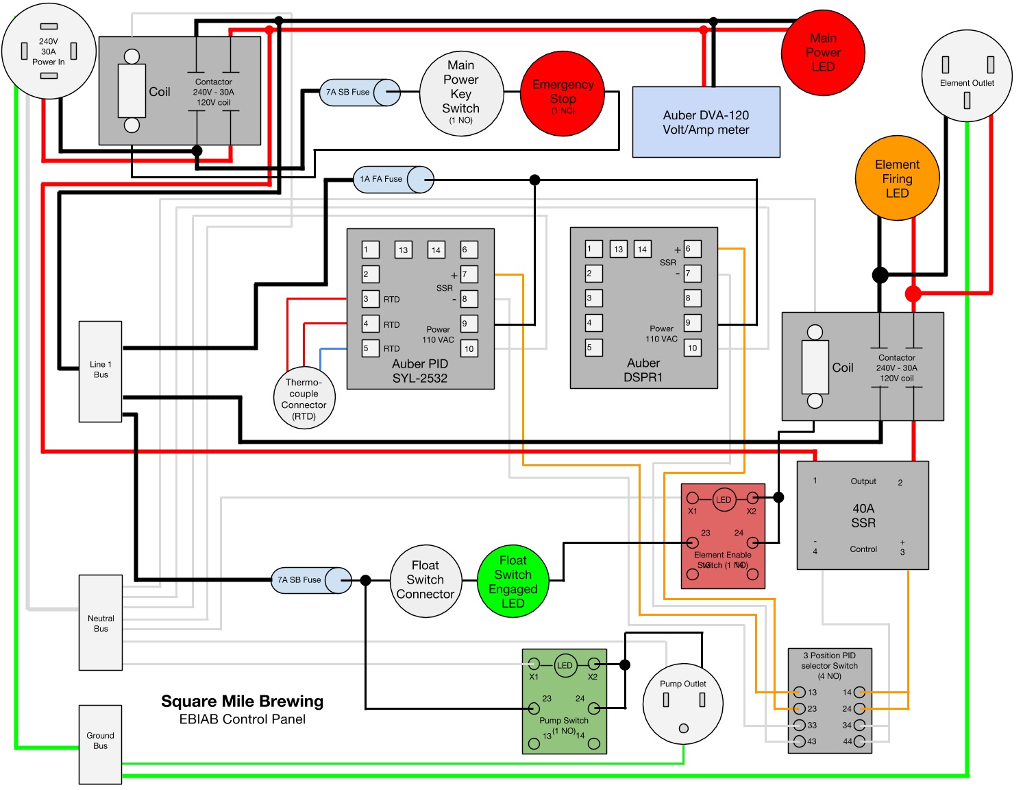
I want to have float switches on my kettles to prevent dry-firing the elements.
Would it make more sense to put the float switch between the PID and the SSR or in front of the coil for the contactor that the SSR is feeding?

If it is between the PID and the SSR the float prevents the SSR from energizing and providing power to the coil.

If the float switch is on the coil then the contactor is prevented from providing power regardless of what is happening down stream.

Does it matter or is there a preference that has some basis?

Also with the adapter from auberins do you remove insulation to spread the terminals apart to make your connections or do you splice the cables to something else? I am realizing the having the cable be over 2 feet long doesn't really provide a whole lot of value in my circumstance.

Thanks for your thoughts and input.

-decoleur
 
Either of the methods you listed would work. I personally would have the switch between the PID and the SSR since that is a low voltage signal (3-32VDC) and the contactor, at least in my case, is 115VAC. Safer to have low voltage traveling out to the float switch and back.

Not quite sure what you're asking in the second question. I didn't need to spread the terminals apart since the PID RTD connections are all right next to each other.
 
I haven't actually wired my panel yet, so keep that in mind, but mine is on the 120V coil line for the contactor that's between the SSR and element. There's also an "element enable" switch between the float switch and contactor coil. Redundant, I know.
 
Still building my panel also, but I'm using 24VDC coil relays for these functions. The relay interrupts power to the 120VAC illuminated selector switch that powers the contactor. The switch illuminates when turned on, but if the relay is not energized, there's no power. The only "high voltage" leaving the panel will be the element power. IMO, 120VAC = "high voltage"...
 
Either of the methods you listed would work. I personally would have the switch between the PID and the SSR since that is a low voltage signal (3-32VDC) and the contactor, at least in my case, is 115VAC. Safer to have low voltage traveling out to the float switch and back.

Not quite sure what you're asking in the second question. I didn't need to spread the terminals apart since the PID RTD connections are all right next to each other.

Thanks WScottCross, I think your comments and the others on placing the Switch between the PId and the SSR make good sense. If given a choice, I think I would rather have the smaller voltage going through the float switch than 120V.

For the second part: the terminals on my pre-made wire currently are coupled so I really cannot spread them more than a inch apart and my PID is on the lid while my SSR is on a heat sink on the top of a 12x16x8 enclosure.
So something has got to give. Has no one had this problem?

poptarts, HarpuaScorpio, PopaFoxtrot, do you have pics or schematics of your builds so I can see what you are up to. I am working on redoing some PJ diagrams to show my final solution and always benefit from seeing others plans.

Thanks for the quick responses.

The Auber float switch that I bought is rated for up to 220V, so that's why I wasn't concerned about it being on a 120 line.

Here's my most recent wiring diagram, the progress of which you can follow in this thread.
ZYisGuq.jpg
 
PopaFoxtrot, do you have pics or schematics of your builds so I can see what you are up to.

No pic's yet. I'm cutting holes in the panel right now - using a stainless box that was originally for outdoor cellular equipment; 1/8" thick and a pita to cut holes in.

The schematic is standard PJ three PID, 240V HLT/BK and 120V RIMS. The 24V circuits are an easy add. I'll try to sketch something up.
 
I have a build thread in my sig, 4 float switches total 2 for pumps 2 for elements.
 
Thanks WScottCross, I think your comments and the others on placing the Switch between the PId and the SSR make good sense. If given a choice, I think I would rather have the smaller voltage going through the float switch than 120V.

For the second part: the terminals on my pre-made wire currently are coupled so I really cannot spread them more than a inch apart and my PID is on the lid while my SSR is on a heat sink on the top of a 12x16x8 enclosure.
So something has got to give. Has no one had this problem?

poptarts, HarpuaScorpio, PopaFoxtrot, do you have pics or schematics of your builds so I can see what you are up to. I am working on redoing some PJ diagrams to show my final solution and always benefit from seeing others plans.

Thanks for the quick responses.

All three of the sensor wires need to be connected to the PID. The PID should have separate outputs that drive the SSR and you need to provide the wiring from the PID to the SSR. What PID are you using?
 
All three of the sensor wires need to be connected to the PID. The PID should have separate outputs that drive the SSR and you need to provide the wiring from the PID to the SSR. What PID are you using?

The temp probe has three outputs and I am using an Auber2362, all good there with length to spare.

The terminals I was talking about were for my float switch. It turns out my float switch is rated at 220AC but the wire isn't that heavy a gauge so I think I will split it between my SSR and my PID.

These build diagrams are awesome. Thanks guys!
 

Latest posts

Back
Top