• Please visit and share your knowledge at our sister communities:
  • If you have not, please join our official Homebrewing Facebook Group!

    Homebrewing Facebook Group

Triac Controllers

Homebrew Talk

Help Support Homebrew Talk:

This site may earn a commission from merchant affiliate links, including eBay, Amazon, and others.

jdgabbard

Well-Known Member
Joined
Sep 27, 2012
Messages
116
Reaction score
8
Location
Tulsa
Bought one of these last night, since it was cheaper than buying the parts to build one.

http://www.ebay.com/itm/400775988169

Who has used these triac or phase angle controllers? Did you find them to be adequate for controlling the boil?

I've used a router speed controller in the past, which is essentially the same thing. However since I'm upgrading to 240v, I needed something that was rated for such, not 120v.


Sent from my iPhone using Home Brew

I bought one a while ago. I think the heat sink it too small because it got way too hot to touch and I quit using it.
 
Were you using a fan? I am planning on mounting it in a 8x8x6 junction box with a PID to control an SSR, but limit power to the element with this. And plan on having a fan on the inside.

Something else I just realized, this appears to have only a single line in, and a single line out. Which throws me off, doesn't 220-240v have two hots, not just a single hot? Im thinking I may have bought the wrong one now...


Sent from my iPhone using Home Brew
 
I bought one a while ago. I think the heat sink it too small because it got way too hot to touch and I quit using it.
I have only checked one datasheet - but for a 4000W max I would assume they are using a 20A SCR. And the datasheet I looked only started derating the max current at above 70°C (AKA too hot to touch). So I wouldn't use that as a basis to discredit these.
Were you using a fan? I am planning on mounting it in a 8x8x6 junction box with a PID to control an SSR, but limit power to the element with this. And plan on having a fan on the inside.

Something else I just realized, this appears to have only a single line in, and a single line out. Which throws me off, doesn't 220-240v have two hots, not just a single hot? Im thinking I may have bought the wrong one now...


Sent from my iPhone using Home Brew

Someone else should confirm this but from the typical DIAC/TRIAC control circuit the controller is wired in series with the load (it is the right part of the diagram). So it goes L1 -> load -> Controller -> L2.
triac-lamp-dimmer-circuit.jpg

The 120V/240V in the US is just that they use centre tapped transformers so the voltage between L1 and centre (N) is 120V and N and L2 is 120v (but out of phase) and between L1 and L2 is 240V. So in reality 240V is not the addition of the 120V phases but it is easier to explain it that way.
 
Mattd2, that schematic is probably what I'm going to need to do. I've only messed with 120v controllers in the past. So I was a little quick to pull the trigger. I noticed afterwards that there were some models that had four connections, 2 in, and 2 out. So that is what confused me. But I'm sure it'll have instructions, or I hope it will...


Sent from my iPhone using Home Brew
 
Were you using a fan? I am planning on mounting it in a 8x8x6 junction box with a PID to control an SSR, but limit power to the element with this. And plan on having a fan on the inside.

Something else I just realized, this appears to have only a single line in, and a single line out. Which throws me off, doesn't 220-240v have two hots, not just a single hot? Im thinking I may have bought the wrong one now...


Sent from my iPhone using Home Brew

I was not using a fan and you are right - it might have been OK with a fan.

I was comparing the heat to the heat put off by a friend's home built controller. The heat sink on his SSR is about the same width and twice as long. It gets warm but not so warm that I can't keep my hand on it and he does not have a fan either.
 
Mattd2, that schematic is probably what I'm going to need to do. I've only messed with 120v controllers in the past. So I was a little quick to pull the trigger. I noticed afterwards that there were some models that had four connections, 2 in, and 2 out. So that is what confused me. But I'm sure it'll have instructions, or I hope it will...


Sent from my iPhone using Home Brew

I have one with 4 input/output posts that I use for a drill speed controller - I'll check tonight if 2 of the posts are just connected together on the pcb and nothing else.
 
I was not using a fan and you are right - it might have been OK with a fan.


I was comparing the heat to the heat put off by a friend's home built controller. The heat sink on his SSR is about the same width and twice as long. It gets warm but not so warm that I can't keep my hand on it and he does not have a fan either.


I know in the HF Router Speed Controller I used for a while the triac is just connected to the back plate. I mounted a copper sink I fabricated and afterwards it was just fine. But that was at 120v. With 220v I can be sure it would have been untouchable. But a fan should fix that.

I have one with 4 input/output posts that I use for a drill speed controller - I'll check tonight if 2 of the posts are just connected together on the pcb and nothing else.


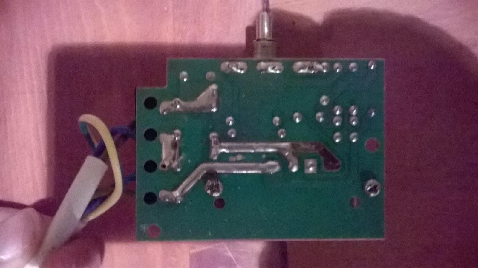
That would be great. If you could, mind posting pictures if the top and the bottom of the board? I am a hobby level electronics guy. I fab my own PCBs all the time. I'd like to see what the schematic is for the board you're using.


Sent from my iPhone using Home Brew
 
Hello:

I bought the 6600w version of this.

Have had two issues so far.

Found that the design put the contacts of the control so close to the edge that when you tightened the nut on the shaft the contact would touch the front panel. In my case it was grounded and I had sparks all over!

It actually only blew the breaker and I was able to fix up the mess, add an insulator and be on my way.

I needed a fan even running it at half rated power.

It was starting to smell even at lower power and I found that there is a fuse holder on the circuit board that does not seem to be rated for this amount of current. It over heated, charring the circuit board at the fuse holder and melted a hole in one side of the fuse.

I have recently updated my element to 4400w and am a little concerned if this can handle the power. I think I will do a sniff and heat test before running a full batch.

If this fails, it think I will redo it with a SSR with a one second duty cycle.

Tom
 
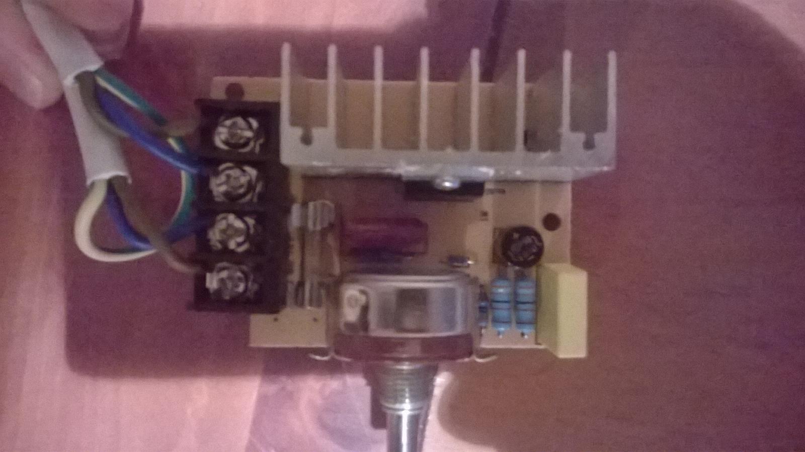
Here are the photos, looks like the "neutral" is just linked and does nothing but pass from one post to the other.

WP_20141008_001.jpg


WP_20141008_002.jpg
 
Here is mine....

Looks identical except the Triac module is a large model as is the heat sink.

Also shown is the overheated fuse holder. I am planning to jumper out the fuse and rely on the upstream breaker.

The last picture shows the melted pot. There appears to been an exposed rivet or solder blob on the contact that touched the front panel when tightened. Although the entire lead vaporized, it turns out not to have been needed as both it and the wiper are connected together.

Although sold as 6500W dimmer I am still unsure if it can handle my 4400w heater. At 3300w it was "smelling" but I now suspect it was the dodgy fuse holder was heating and not the Triac.

You definitely need a fan on this!

TomImageUploadedByHome Brew1412785211.320090.jpgImageUploadedByHome Brew1412785240.889951.jpgImageUploadedByHome Brew1412785257.351059.jpg
 
Sorry, forgot the schematic...

The chip is BTA60-800B.
I cannot find much about it other than it is rated 60A at 800V.

I want to put about 18 amps through it so might have to beef up the pub traces.

Tom

..ImageUploadedByHome Brew1412789048.596907.jpg
 
Sorry, forgot the schematic...

The chip is BTA60-800B.
I cannot find much about it other than it is rated 60A at 800V.

I want to put about 18 amps through it so might have to beef up the pub traces.

Tom

..View attachment 228255

Do you know what's the point of the bridge rectifier?
Nevermind - I found out it is to increase the responsiveness at low seetings (i.e. to remove the likelihood you need to turn it up to get it starting and then ease it back down to your set point.)
 
Here is mine....

Looks identical except the Triac module is a large model as is the heat sink.

Also shown is the overheated fuse holder. I am planning to jumper out the fuse and rely on the upstream breaker.

The last picture shows the melted pot. There appears to been an exposed rivet or solder blob on the contact that touched the front panel when tightened. Although the entire lead vaporized, it turns out not to have been needed as both it and the wiper are connected together.

Although sold as 6500W dimmer I am still unsure if it can handle my 4400w heater. At 3300w it was "smelling" but I now suspect it was the dodgy fuse holder was heating and not the Triac.

You definitely need a fan on this!

TomView attachment 228239View attachment 228240View attachment 228241

I was unsure of what you were meaning about the nut on the shaft and shorting out - I now see the issue! Thanks
 
Hrm. Curious as to why they would only connect the second lead from one post to the other post. Unless it is meant as just a way to add strength to the setup, read: keep the cable from pulling out.

That is weird about the fuse holder tho. You'd think that if it was rated for 6500w they wouldn't have overlooked that. Are you sure you're not pulling more amps than that? Have you metered it?


Sent from my iPhone using Home Brew
 
I think the terminal block is meant to have an input cable and an output cable. This just makes it neat and easy to connect. (I made the connection with wire nuts in the case as I would rather remove any heat producing connection off the board)

I kind of take the specs with grain of salt. (Kind of like the maximum strength of a rope) My last heater was a 3300w and when it was on full I could smell some something I didn't like, thinking it was the circuit board overheating. This would have been less than 14 amps. The fuse end cap actually melted and arced out causing an open (the fuse itself never blew). This appear to be what caused the heat and the board underneath that side of the holder is darkened.

I believe that if I beef up the traces a bit and jumper out the fuse the unit should do for my new 4400w heater. I have built it in a computer powersupply case with the original fan running full blast.

The element should handle this 18 amps, it is just the heat I have to get rid of.

I started brewing with an "infinite" switch (electric range replacement) so I wired it in parallel as I did not want to run the dimmer on full with the 4400w element. Good thing I did, as the dimmer gave out before I reached boil and I switched over to using switch. However as it only switches on and off the boil was a bit erratic. (4400w even in a 10 gallon boil is quite ferocious).

I will do the same thing again in case the dimmer melts down. I figure I have nothing to lose in trying it, and I should be be able to smell overheating (an ir camera would be good)

Will let you know how it works/not works.

Tom
 
Good news!

I did a trial run with 5 gallons.

No strange noises or smells and the fan kept everything nice and cool.

Going through my 10 gallon process....

(I have an old audio VU meter connected that I have adjusted to be full scale when full on)

Full until reach mash temp
About 75W to maintain mash temp
Full to get to sparge temp
Full to reach boil temp
About 2500W to boil

The only thing a PID controller would do is let me walk away and have it stop at mash temp automatically. Otherwise I just dial back the control at the proper time.

I was thinking about a 5500W heater but was concerned with scorching (my stubby 3000W made some crazy charcoal brew. The 4400W seems to be the same length as the 5500W, meaning less watts per inch) and I figured I could safety stretch my present cabling to 18 amps but would have to rewire for 23 amps. (the code for temporary, free air wiring allows some leyway)

The 25% faster heating with 5500 over 4400 was not such a big jump after the 45% jump from 3000 to 4400. In the end I think it is the "sweet spot" in my set up.

I am curious to see if your control can handle the 5500W long term.

Tom
 
I have a keggle with insulating foam on the bottom and fully wrapped with Reflectix.
A lid and piece of foam over the top. It is all inside so little "wind".

My last mash was done without the dimmer and I was surprised that it only dropped a couple degrees in an hour.

Tom
 
Tegra, I don't know how I missed all your responses. I gave up on this particular application, along with building my e-brewing controller. Life got in the way, you know. I have though about repurposing these to 120, but if I'm not mistaken, I think there may be an issue with the POT on these. I think they are voltage specific, although I'm not sure. How is this working out for you? Everything still good?
 
Hello jdgabbard!

Yes everything is well! I have made about 5 batches since my fix and everything is cool.

Feel a little ghetto after seeing all the fancy builds, but this does exactly what i need it to and is cheap and easy to use.

I take back all the bad things I said about this unit. With a few mods it is a great little unit.


I see no reason it cannot also work with 120v. It certainly can't handle the same wattage but should be as much current as a 15 Amp circuit can handle.

Tom
 
Yeah, and it probably wouldn't have as much of a problem with heat as a 240v build would be. I need to get back to work on this. I have most of the parts I need. 8x8x6 pvc junction box with two MyPin PIDs fitted, a digital ammeter, and this triac controller. I also have 2x dual 120 plugs fitted. Power in is one of those female 3-prong 240v twist lock plugs. It would be easy to repurpose it to 120v. I may break it out tonight...
 
It is the current (actually the resistance of the Triac multiplied by the current) that causes the heat. So this can handle only half the current at 120v.

Even after modding this it will only handle 2500w at 120v (5000 at 240v). (I am running 4400w at 240 which equates to 2200w at 120)

That is the beauty of higher voltage, you can use thinner wire and smaller control devices for the same power.

As soon as you get close to 2000W it is good to start thinking 240.
(My first setup grabbed 240 from the duplex outlets on the kitchen counter with two plugs into the same receptacle)

Tom
 
Well, I got on the ball and started putting mine together. I'm wiring it for 120v, as it is really my only option right now. But conversion to 240v wouldn't be too hard, as most of the components are already rated for 240v... When/if I do go that route in the future I'll have to buy a 12x12x6 box instead of this 8x8x6.

There is going to be enough room for the one SSR I'm going to use, and a fan in the bottom portion of the picture. I'll be mounting the heatsink on a plate that will be screwed to the back of the box. The fan will be mouted inside with an attached board with a transformer and diode bridge to regulate the current to 12v DC. I may etch the circuit myself, or just steal the ready made board from a wall wort. I could probably go with a iphone wall wort and a 5v fan now that I think about it.... All the wire for the load components is 14g, the wire for the MyPin PIDs and the Ammeter are 18g. The power in is using 10g.

I need to find a fairly small kill switch, and some decent switches for the pumps. The temp probes are going to be wired to 3-pin panel mount XLR sockets that will be on the left of the 120v sockets. So far I think it's going to work good.

I plan on using this with 1500-2000w elements for 6.5g boils. My triac controller is a 4000w model, so I should be ok, judging from what you're telling me.

View attachment ImageUploadedByHome Brew1428097660.621321.jpg

View attachment ImageUploadedByHome Brew1428097677.982351.jpg
 
I think you will be fine if you have made the mods to the pcb of the controller and have lots of air moving over the heat sink (I guess you could cut a hole on either side of the case for fan and exhaust?)
 
I didn't mod the pcb. I plan on ventilating it and seeing how it runs. I mess with electronics as a hobby, so if I see a problem, I'll make the fix.
 
Mine was rated at 6600W but blew out at 3300W.
That is only about 14 Amps and you want to put 18 Amps through yours.

Here is a link were another guy also burnt his up....

https://www.homebrewtalk.com/showthread.php?t=494977

The unit is fine it is just the mini fuse that over heats.
If you beef up the traces on the board and jumper out the fuse it has been fine for me at 18 Amps.

I was very much down on this cheap control until I "fixed" it.

Tom
 
I wouldn't be using that many amp. More like 13 amps. But, may still need to do that... What material did you use as a jumper? I would assume heavy guage wire...
 
Back
Top