TiltBridge - Tilt-to-WiFi Device for Tilt Hydrometer

Homebrew Talk - Beer, Wine, Mead, & Cider Brewing Discussion Forum

Help Support Homebrew Talk - Beer, Wine, Mead, & Cider Brewing Discussion Forum:

This site may earn a commission from merchant affiliate links, including eBay, Amazon, and others.
I’ve chatted with Thorrak a little about this, but figured I would make this public, in case someone else wants to do this...

I would like to power the Lolin D32 Pro with my 5V DC Power Supply, but I would also like to hook up a USB, when needed, and not fry the board.

I’m hoping someone can confirm.

I think if I tie the EN pin to a Ground pin, and then run my 5V DC through a level shifter to 3.3V. I can then run my Power to the 3V pin on the D32.

Does this sound right?

I’ve attached the D32 Pro schematic for reference, and the YouTube video about the EN pin.

View attachment 657786
View attachment 657788


Thanks in advance.


I think you would need one of these https://www.adafruit.com/product/2165 (and then tie EN to ground) but someone with more electrical knowledge than I have (hi @day_trippr !) might be able to better comment/confirm
 
The one part of the above you definitely do not want to do is use an actual "level shifter" to drop your 5V power supply down to 3.3V as level shifters deal with very small currents, not enough to power your esp32.

Looking at the schematic, there is a node where the USB 5V ("VBUS") and battery voltage "VBAT") merge at the input to the 3.3V linear regulator (U2).

upload_2019-12-19_23-31-58.png


Using a diode [edit: in a similar fashion and orientation as the USB VBUS connection to the highlighted node] you could very safely bring an external 5V supply to that node, find a common ground for the return, and be good to go...

Cheers!
 
Last edited:
The one part of the above you definitely do not want to do is use an actual "level shifter" to drop your 5V power supply down to 3.3V as level shifters deal with very small currents, not enough to power your esp32.

Looking at the schematic, there is a node where the USB 5V ("VBUS") and battery voltage "VBAT") merge at the input to the 3.3V linear regulator (U2).

View attachment 657798

Using a diode you could very safely bring an external 5V supply to that node, find a common ground for the return, and be good to go...

Cheers!

One of the major complaints about the D32 is that they don't expose VIN as a pin. :(
 
Looking at the schematic again, if either of JP2 pins 10 and 11 is truly a "no connect", and if U2 pin 1 is visible, one wire - maybe two if there is no other way to ground the external power supply - would be all that's needed...

[edit - big one]
Except...I just realized the battery power cutout circuit provided by Q1 (which watches the USB VBUS and goes open if VBUS = true) would not "see" an externally applied power source at the node I was using. Level of difficulty just jumped a bunch. I'll think about it tomorrow, but one could buy a cheap powered hub :D

The one issue I'd be concerned about using an "add-on" 5v->3.3v LDO and tying into the board's 3.3V net is some LDOs don't like current sharing - which would be the case as the battery current to the on-board 3.3V reg is "always on" unless there's a USB voltage present, and in the case that the OP connects both a USB device and his external power supply simultaneously....

Cheers!
 
Last edited:
I'll think about it tomorrow

Thank you for your input on my question. I’m “attaching” a reply I found on the interwebs concerning powering the D32. This topic is way out of my wheelhouse...

“I figured it out with the help of Dave Bird's Tech Note 097 which explained how the on-board regulator can be disabled (open-circuit) by tying the EN pin to ground. This allows direct application of 3.3V onto the 3V pin, powering the board directly. Additionally, if EN is held low, a USB cable can be connected and serial comms continues to operate, because the CH340C has 3.3V supply. Power from the USB is shorted to ground via 100kohm resistor, which is no big deal.

An alternative is to power at 4.2V via the battery connector. The TP4054 can take up to 7V on its BAT pin, and the charger won't enable unless the voltage drops below 4.2V, so one could also supply, say, 5V via this connector. The D2 diode will protect USB.

One third option is to supply 5V via VBUS pin, ensuring it is as close as possible to the USB voltage (a difference of a few tenths of a volt may not cause any problems). If paranoid, a diode can be used to protect the USB supply.”

Full disclosure...I don’t know anything about what I just quoted!

...but one could buy a cheap powered hub :D

This isn’t off the table. Yeah, the powered hub is cheap....but I’ll find a way to make it expensive....I always do!
 
Looking at the schematic again, if either of JP2 pins 10 and 11 is truly a "no connect", and if U2 pin 1 is visible, one wire - maybe two if there is no other way to ground the external power supply - would be all that's needed...

[edit - big one]
Except...I just realized the battery power cutout circuit provided by Q1 (which watches the USB VBUS and goes open if VBUS = true) would not "see" an externally applied power source at the node I was using. Level of difficulty just jumped a bunch. I'll think about it tomorrow, but one could buy a cheap powered hub :D

The one issue I'd be concerned about using an "add-on" 5v->3.3v LDO and tying into the board's 3.3V net is some LDOs don't like current sharing - which would be the case as the battery current to the on-board 3.3V reg is "always on" unless there's a USB voltage present, and in the case that the OP connects both a USB device and his external power supply simultaneously....

Cheers!

Would this be true if no battery was present, and the on-board voltage regulator was disabled by tying EN to ground?
 
[...]

“I figured it out with the help of Dave Bird's Tech Note 097 which explained how the on-board regulator can be disabled (open-circuit) by tying the EN pin to ground. This allows direct application of 3.3V onto the 3V pin, powering the board directly. Additionally, if EN is held low, a USB cable can be connected and serial comms continues to operate, because the CH340C has 3.3V supply. Power from the USB is shorted to ground via 100kohm resistor, which is no big deal.

If I have it correctly, this requires always having the add-on 3.3V regulator connected and turned on. I actually missed that the OP was planning on a "permanent" external power source, so this solution appears to satisfy the requirements. And the small current through R4 to the grounded EN pin at U2 is indeed a non-issue, similar constructs are used all the time for configuration jumpers.

An alternative is to power at 4.2V via the battery connector. The TP4054 can take up to 7V on its BAT pin, and the charger won't enable unless the voltage drops below 4.2V, so one could also supply, say, 5V via this connector. The D2 diode will protect USB.

Not a fan of this solution as the battery itself would be at some risk.

One third option is to supply 5V via VBUS pin, ensuring it is as close as possible to the USB voltage (a difference of a few tenths of a volt may not cause any problems). If paranoid, a diode can be used to protect the USB supply.”

Be paranoid. Use a diode, hook the 5V supply to the anode, connect the cathode to the anode of D2. U2 will see a small voltage drop with no USB device connected but still above the LDO cutoff considering the 3.3V loading on an esp32...

Cheers!
 
If I have it correctly, this requires always having the add-on 3.3V regulator connected and turned on. I actually missed that the OP was planning on a "permanent" external power source, so this solution appears to satisfy the requirements. And the small current through R4 to the grounded EN pin at U2 is indeed a non-issue, similar constructs are used all the time for configuration jumpers.

OK..please bare with my ignorance.

I'm going to want to run my 5V Line from my Power Supply to the Unregulated Vin of a 3.3V Regulator. (should I use capacitors in the circuit, or can I get by without them?) I will then run a 3.3V line from the Regulated Vout to the 3V Pin on the D32 Pro. (Do I need a heat sink on the Regulator?) At 240MHz, the D32 Pro pulls 68mA and I calculated a generation of 0.1156W of heat. On the D32 Pro, I need to jump the EN pin to a GND Pin.
 
Yes, if you ground the enable pin on the D32's 3.3V LDO regulator, and then use a (similar) 5V to 3.3V LDO , drive that with your external 5V source, and run the output to the 3.3V network, you'll have accomplished the aims of the first solution listed. High frequency bypass capacitors (0.1/0.01 uF) are never a bad idea on both In and Out power rails at the loads and sources. It's what we do in commercial-grade stuff where a double-sided gum stick size device is often encrusted with 50 to 60 different high frequency decoupling capacitors.

I've read of up to 116 mA on the 3.3V rail when the wifi is blasting but tbh that's after a cursory look around. If you can fit a sink it might be a good idea...

Cheers!
 
Sure, that is a small switching power supply ("buck convertor") which would certainly work (more than enough output capacity) but be a bit of overkill when a three terminal LDO would do the job...

Cheers!
 
Sure, that is a small switching power supply ("buck convertor") which would certainly work (more than enough output capacity) but be a bit of overkill when a three terminal LDO would do the job...

Cheers!

I greatly appreciate all the help on this subject.

“Overkill”?!? Have you seen our brewing set-ups? LOL

Seriously, I know what you’re saying (why spend $5 when you can spend $0.50) For me, and my electronics skill set... throwing a Lincoln at a device to solve my question is a winning proposition.
 
Ok, I just got some Tilts, I have stainless fermenters, and I want the wifi, so...I'm going to give this a try! hopefully I'm better off than the Pi things I have tried! :eek:
 
Ok, I just got some Tilts, I have stainless fermenters, and I want the wifi, so...I'm going to give this a try! hopefully I'm better off than the Pi things I have tried! :eek:
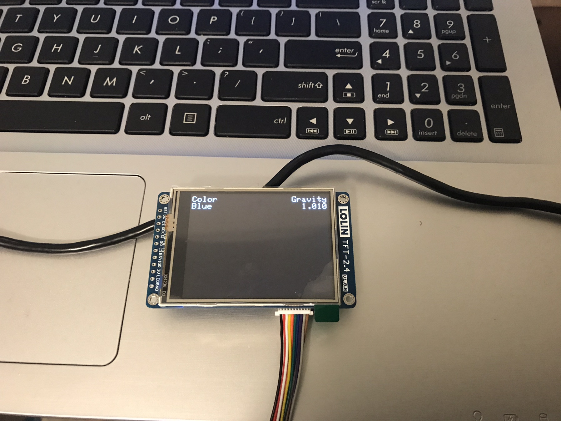
If you’re just now buying hardware, get the three components I linked earlier from LoLin. Firmware still isn’t finalized/in the wild, but it’s a better option than having to struggle with the various manufacturers of the OLED screens.
 
If you’re just now buying hardware, get the three components I linked earlier from LoLin. Firmware still isn’t finalized/in the wild, but it’s a better option than having to struggle with the various manufacturers of the OLED screens.
Thanks! I just bought the new stuff.
 
If you’re just now buying hardware, get the three components I linked earlier from LoLin. Firmware still isn’t finalized/in the wild, but it’s a better option than having to struggle with the various manufacturers of the OLED screens.

The components linked earlier in the thread just arrived. Is there a way to get the beta firmware? Or is the release imminent and I just need to be more patient :)
 
The components linked earlier in the thread just arrived. Is there a way to get the beta firmware? Or is the release imminent and I just need to be more patient :)
With Github there's generally a way - however I'd suggest if @Thorrak's not released it yet you would probably be better off waiting.

Quite honestly, I consider anything given away for free "best effort beta all the time" (including my own work) so best to wait for a release. :)
 
I flashed an esp32 with OLED with the firmware and connected to the access point to setup the WIFI and that's all working. The TiltBridge enumerates the tilts and displays them on the OLED. I then followed the directions for google sheets and every thing works up to the first data entry. The sheet label entered on the TiltBridge setup form is created and one row is added. After that no other data rows are appended to the sheet. Any ideas on where to look to troubleshoot?

thanks
 
As a side note I had two esp32's is that they had the blank OLED after flashing with esptool.py. I then uploaded an example sketch via the Aurdino IDE and that worked. Then the upload via esptool.py worked. Don't know what the upload of the example sketch did, I used the NIST Time example.
 
Not a PC noob here but I've never used Python. I bought this board.

Installed python 3.8, then pip. With pip I installed esptools. and I can't seem to run it. Not using a command prompt, Windows PowerShell, python nor pip through powershell. What am I doing wrong?
 
What happens when you do?

Python 3.8.1 (tags/v3.8.1:1b293b6, Dec 18 2019, 23:11:46) [MSC v.1916 64 bit (AMD64)] on win32
Type "help", "copyright", "credits" or "license" for more information.
>>> $ pip install esptool
File "<stdin>", line 1
$ pip install esptool
^
SyntaxError: invalid syntax
>>> python -m pip install esptool
File "<stdin>", line 1
python -m pip install esptool
^
SyntaxError: invalid syntax
 
You had two entry errors: the dollar sign broke the first attempt, and using python to run pip was the second.
This is all you need:

pip install –upgrade esptool

https://pypi.org/project/esptool/

Cheers!

Running the line in python I get:
>>> pip install -upgrade esptool
File "<stdin>", line 1
pip install -upgrade esptool
^
SyntaxError: invalid syntax
>>>


running it with pip using powershell:

PS C:\Users\PC> pip install -upgrade esptool
ERROR: Invalid requirement: '–upgrade'
 
PS C:\Users\PC> $ pip install -upgrade esptool
$ : The term '$' is not recognized as the name of a cmdlet, function, script file, or operable program. Check the
spelling of the name, or if a path was included, verify that the path is correct and try again.
At line:1 char:1
+ $ pip install –upgrade esptool
+ ~
+ CategoryInfo : ObjectNotFound: ($:String) [], CommandNotFoundException
+ FullyQualifiedErrorId : CommandNotFoundException
 
When you installed python for Windows did you install to “path”?

BTW...the board your using can be problematic and is inconsistent with successful installations (too many variables with the suppliers of the board). The project developer is recommending the Lolin D32 Pro with the Lolin TFT touch screen.
I wasn't running the commands with the board connected...is that the problem?
 
  1. Do not type the leading $ ... that is there to indicate you should be root on a Unix system.
  2. You should be using Python3 so you need to use pip3.
  3. When you use the full word for an option, you need to use two dashes.
Therefore your command is:
Code:
pip3 install --upgrade esptool
 
  1. Do not type the leading $ ... that is there to indicate you should be root on a Unix system.
  2. You should be using Python3 so you need to use pip3.
  3. When you use the full word for an option, you need to use two dashes.
Therefore your command is:
Code:
pip3 install --upgrade esptool

It's installed together with pyserial. Next, the instructions say to use "esptool.py" to run, I get this:

>>> run esptool.py
File "<stdin>", line 1
run esptool.py
^
SyntaxError: invalid syntax
 
You are trying to run it underneath Python, that is incorrect. Simply type:
Code:
esptool.py
... from the command prompt - not in Python.
 
Got it to flash but I had to do it differently. I copied cmd.exe to the esptool folder together with the 3 firmware files. Ran the command "esptool.py --chip esp32 --before default_reset --after hard_reset write_flash 0x10000 firmware.bin 0x8000 partitions.bin 0x3D1000 spiffs.bin" with the "boot" button pressed and it got it done.

Tha last line in cmd says "Leaving...
Hard resetting via RTS pin..."

The screen went dark and now I can't do anything else.
 
Last edited:
Back
Top