• Please visit and share your knowledge at our sister communities:
  • If you have not, please join our official Homebrewing Facebook Group!

    Homebrewing Facebook Group

This is losely brewing related, but a question.

Homebrew Talk

Help Support Homebrew Talk:

This site may earn a commission from merchant affiliate links, including eBay, Amazon, and others.

bracconiere

Jolly Alcoholic - In Remembrance 2023
Joined
Jan 19, 2018
Messages
27,724
Reaction score
17,266
Location
S.AZ
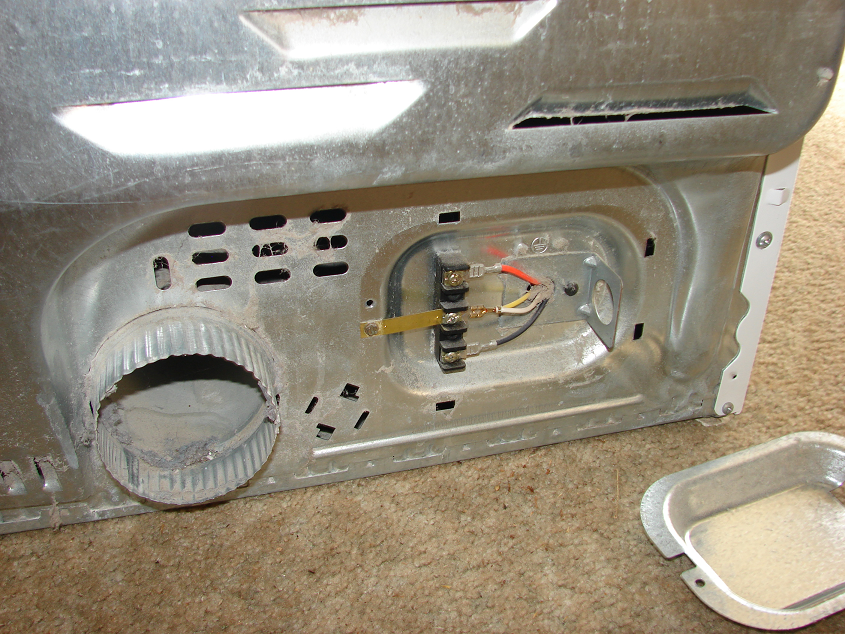
So i just scored a free dryer without a cord for deculming my malt the easy way....it has four wires, going to three terminals, no cord. i'd need a longer cord in way so i can put it on the back deck...but my dryer i have now uses a four wire plug? i was looking at cords for dryers and see there're are both 4 AND 3 wire plugs....this is what the dryer looks like..
1633801116515.png


what exactly do i need? will a four prong cord work with this dryer?

and if not can i somehow convert the drum, and fan to 120v? all i need is the thing to spin, and blow air over the malt.....
 
so take the little jumper bar off for the 3 prong dryer, and hook the ground up to the screw on the chasis?
 
thank you....i have it hooked up with a 120v power cord right now, no love....it's an old dryer..no circuit board or anything, but acrost the resistor, that i get a dead circuit...

what if just tear the thing apart, and hot wire the motor? will 120v run it?
 
thank you....i have it hooked up with a 120v power cord right now, no love....it's an old dryer..no circuit board or anything, but acrost the resistor, that i get a dead circuit...

what if just tear the thing apart, and hot wire the motor? will 120v run it?
Probably not. It might be possible to rewire the motor for 120V, but I am not a motor expert.

Brew on :mug:
 
Probably not. It might be possible to rewire the motor for 120V, but I am not a motor expert.

Brew on :mug:

i was thinking it'd be like using my fan speed controller, maybe just run slower.....trying to figure out how to get the side panels off right now...lol :mug:
 
i have it hooked up with a 120v power cord right now, no love....
That's probably not gonna work, it may need a 240V 3-wire connection. There could be logic inside that prevents it from running on one leg. Can you borrow the 4-prong cord from your working dryer to check?

BTW, to which terminal do you have the black wire connected? And white to white?
 
actually i got the side off this thing, (eventually, lol), and the motor says 115V 60hz.....just need to figure out the wiring, because it has like 6 terminals on it.....
 
actually i got the side off this thing, (eventually, lol), and the motor says 115V 60hz.....just need to figure out the wiring, because it has like 6 terminals on it.....
That will make it easier. Kind of surprised that it is not a 240V motor.

Brew on :mug:
 
just to double check my thinking on this....i tested every terminal for conductivity, in every combo possible, nothing. no matter how i tried it? so the ancient old dryer is dead isn't it?


and i think the $200 compact dryer i ordered off ebay, they're trying to rip me off...deculming is a tough one to figure out how to do 'easy'...maybe easy is why i'm having problems....
Was the dryer "on" when you checked for continuity? If all the switches are off, then there shouldn't be any continuity between any of the power input terminals.

Brew on :mug:
 
Was the dryer "on" when you checked for continuity? If all the switches are off, then there shouldn't be any continuity between any of the power input terminals.

Brew on :mug:


no i just check the terminals on the motor? i would have thought there would be some continuity between the motor power terminals, they just hook up to a big copper coil right? now that i think about it, i guess one goes to the magnets, and the other the copper coil.... 🤔


i'll keep poking at it....
 
i guess one goes to the magnets, and the other the copper coil....
Anchor and stator...

Isn't there a diagram on a metal plate attached to the motor?
There may also be a capacitor involved to get it started, and/or a starter winding.

Is there a belt between the motor and drum?
 
Is there a belt between the motor and drum?

yeah, and i have an unused bench grinder i picked up at a garage sale a while back, been think of see if maybe i can fit in to the thing....


yeah, the tracking number says it came from IL, but the sender requested it returned, for some strange reason now it's going to IN...? was going to have it tomorrow....then there was a crags list with a like new dryer for $30 locally, called them, already sold....I DECREE I WILL FIND A WAY NOT TO HAVE TO DECULM BUCKET TO BUCKET ANYMORE! ;) lol :mug:

right now i'm thinking, turn the drum...put a box fan in front of the door...

(and this is still sorta electric brewing related...i think, if i get it figured out, maybe someone else will find it handy for when malt goes even above $2/lb)
 
If you can take the motor out( I know big pain) you can wire it up on a bench and find out whats wrong possibly. The motor might be done but it also might just need a start cap or regular cap. Usually you can tell if you can spin the shaft by hand (when wired) to get it started. good luck.
 
For electrical dryers, the 220 VAC is used to power the heat source. One leg or 120 VAC is used for the blower motor and the tumbler motor. Has dryers only use 120 VAC.

120 VAC wire color standard is: white is neutral (the left or large prong on a polarized AC cord & outlets), black OR red is hot (the right or smaller prong on a polarized AC cord or outlet). Ground is bare copper or green (the bottom middle prong on a polarized AC cord or outlet). The electrical outlet here in North American standard polarized plug.

For 220 VAC wiring, white is neutral and black and red are the two hot legs.

Good luck with your decumling dryer build.
 
If you are trying to use 120v there would be two options.hot leads are top and bottom and center one is neutral and ground. So try hot to top and neutral white to center. If it does t
work, move black to bottom. If it doesn't work. then motor is trash or controls are trash. The heater coil is the ONLY 240v part of the mix.
 
the model of the motor, which actually would be better direct wired any way, is 5kh26jj064s...i can take a pic of it....

but i can't find a wiring diagram on google....

The heater coil is the ONLY 240v part of the mix.


that's what i was thinking, and i don't need it to heat, just spin and blow.....


so i haven't given up on the motor, and just putting a switch on a cord yet.....
 
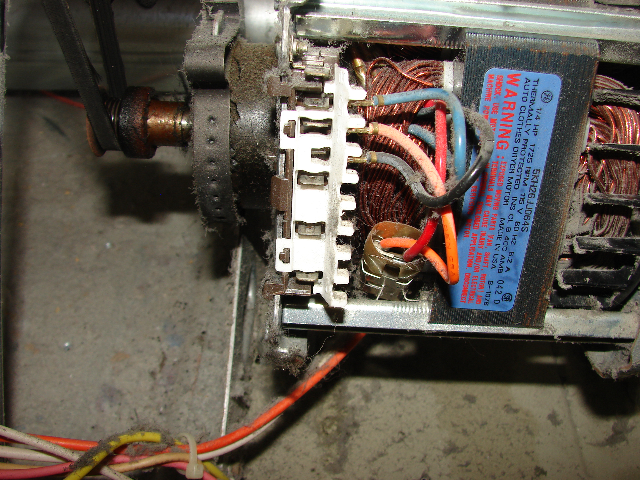
here's what the motor looks like....

1633899608177.png


if any one can tell where to hook a power cord up to it GREAT!
 
If that orange and white are coming out at the motor, then that is most probably the line (orange) and neutral (white)


the orange and white that go under it, go to something in the fan box. probably the dryness sensor.....
 
You might find a wiring diagram for the whole dryer at appliance parts website.


there was one in the dryer box when i opened it up....but it doesn't really tell me how the motor is hooked up, or was.....if i could remember which one it was, and where one of the wires straight from the 'original' plug went someplace at the bottom..i think second from very bottom....i'm eyeing the top three, because they have wires going into the motor's guts....don't want to fry the thing though...if it works at all....
 
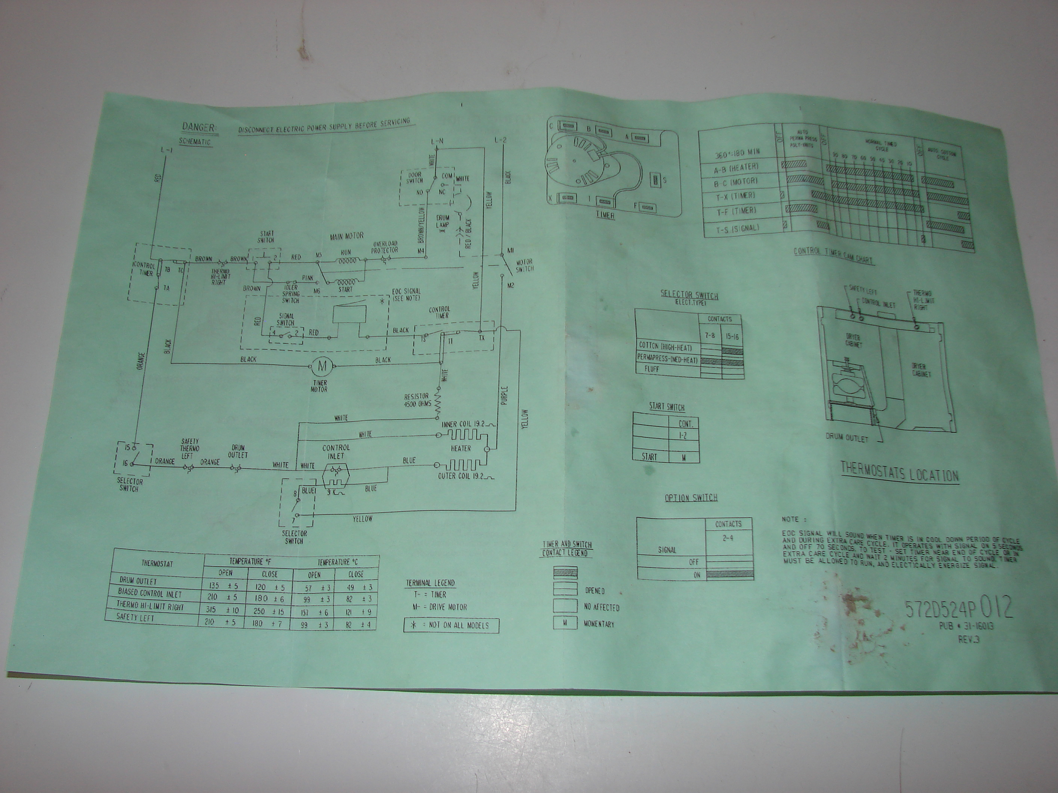
here's what was in the dryers compartment....probably be more useful if i remembered where the wires i dissconnected went originally...


1633901597274.png


if that helps anyone, help me? ;) :mug:
 
That diagram is much more helpful than the picture. This motor is an AC induction motor. These motors don’t use magnets. These motors are very durable, inexpensive to manufacture and easy to turn on (apply AC power) and easy to turn off (remove AC power). The RPM speed is determined by the motor design itself. This motor has a motor starter winding as IslandLizard suggests. The starter motor winding provides high torque to start the drum turning.

From the picture, it looks like some of the wiring has been disconnected. This may complicate things. Hopefully you remember how the wiring all goes back together. So to test just the motor, I suggest connecting 120 VAC as follows: connect Neutral to the Brown/Yellow wire coming off the door switch, node M4 on the diagram, and hot (refer to the details I gave in post #18) to the Red wire coming off the Start Switch, node M5.

Other details …
1. The diagram shows the motor windings on the top left hand side (using the vertical crease in the diagram as a page separator) where it says MAIN MOTOR.
2. The bottom left corner of the first page of the diagram has a TERMINAL LEGEND. To me this implies that there might be a motor terminal block (M- = DRIVE MOTOR) where you can more easily make the above recommended electrical connections.
3. I am guessing that the timer terminal block is the whitish terminal block with the push on connectors that is shown in the picture. If this is correct, then the timer motor maybe part of that motor assembly in the picture.


unfortunately, i don't remember where the wires went on the motor...for some reason i didn't think twice disconnecting, thinking i could just look it up.....


i'm having trouble understanding why this motor has some many hook ups though?

i do appreciate your response... :mug:
 
Come on Bracc you got this. From what I gather your a smart son of a b. Brew on!


LOL, thanks for the kind words....but i'm actually slow.


i think the motor might be fried. because it's a 120v dryer, and even when i hooked it up like intended, it didn't work...just was hoping, maybe it was one of the resistors or something and could hot wire it...
 
LOL, thanks for the kind words....but i'm actually slow.


i think the motor might be fried. because it's a 120v dryer, and even when i hooked it up like intended, it didn't work...just was hoping, maybe it was one of the resistors or something and could hot wire it...

Keep working it man you got this!
 
Keep working it man you got this!


i'm thinking to myself, this is why they say "if it ain't broke, don't fix it" because at this point if it ever did work, it probably will never again..... :mug:
 
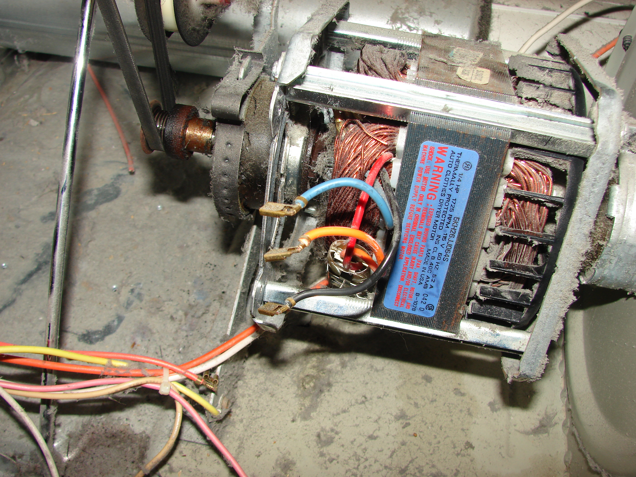
another pic, aparently all the connectors just slips out, i removed it, and disconnected the only wires going to the motor....any ideas people?


1633997896677.png


i'm confused why there are 3 wires....is the orange going to some sorta tiny start cap?
 
i should mention this dryer says it works with either 120v OR 208v......would the other lead be for stepping down 220v?
 
googling tells me, black and orange->red should both be connected to hot, and blue to neutral? as my best guess?
 
How about searching for something like dryer brand dryer model motor replacement
There might be a video showing how to do it for that or a similar model
 
How about searching for something like dryer brand dryer model motor replacement
There might be a video showing how to do it for that or a similar model


i have, but i've found it more helpful looking at DIY dryer motor project videos....because i just need the motor to turn the drum and fan.... @hout17 i haven't given up yet! keep the light on for me! :mug:

(it still hasn't started sparking and caught fire yet!)
 
i have, but i've found it more helpful looking at DIY dryer motor project videos....because i just need the motor to turn the drum and fan.... @hout17 i haven't given up yet! keep the light on for me! :mug:

(it still hasn't started sparking and caught fire yet!)

One of them might tell you which wire does what. Or how to hook them back up so you can see which was which.
 

Latest posts

Back
Top