I noticed that too. I was looking at some parts on their ebay site and clicked on their contact us page. It listed tamas@pioneerbreaker as the contact. I googled pioneerbreaker and almost all of the parts I need have free shipping, when ebay is like 11 bucks.
You are using an out of date browser. It may not display this or other websites correctly.
You should upgrade or use an alternative browser.
You should upgrade or use an alternative browser.
The cold sucks, going electric
- Thread starter snail
- Start date

Help Support Homebrew Talk:
This site may earn a commission from merchant affiliate
links, including eBay, Amazon, and others.
Yeah, those are cool....I'm wishing I used those, because I'll be using DIN circuit breakers. But, I spent about $40 on bus bars...so I need to use 'em.
I'm using these bus bars and am extremely satisfied:

DIN mount is great too, but I wouldn't fret over using bus bars. I suppose it comes down to your particular panel layout, and each will be different.
TB
ScubaSteve
Well-Known Member
- Joined
- May 21, 2007
- Messages
- 3,673
- Reaction score
- 91
Here's what I was talking about with the PB and estop. If anyone sees a problem please weigh in.
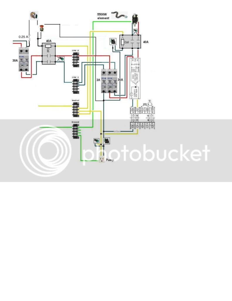
On my system I used a 3PST main power contactor, and that is switching the neutral line so I was able to connect both the start and latching part of the circuit through a single contact block on the estop. If you go with a DPST contactor, as you have diagramed, then you will need to use 2NC contact blocks on your estop. Have the start button wired to one of the contact blocks and the power coming from your 3 A breaker coming into the other contact block. Jump the other side of the contact blocks together and into your power contactor's coil. This will have your estop functioning as a total system shutdown, as it should. If you do not use two contact blocks and instead tie both lines through a single contact block you could power the 3A circuit by pushing your start button even while the estop was triggered, which wouldn't be what you want.
This may be a little late, but Trigger is right. The momentary pushbutton and e-stop seem to be wired wrong. As pictured, they only kill power to your elements and pumps. They should be in series and the output of the E-Stop should be the black wire that leads to the "main" contactor on the left. That way you'll need to have the momentary pushbutton engaged AND the E-Stop (actually a NC switch) should be engaged in order to have a power ON condition. If you push the pushbutton off, or hit the e-stop, it kills power to the main contactor and the ENTIRE system goes dead. What if something happens IN the box? You'l want to turn the entire thing off.
ScubaSteve,
I'm a little confused now. I thought I was good to go with the most recent diagram trigger revised. The way I'm reading it is you push the momentary switch, which only allows power to go through it until you let go. That allows power to go through the main contactor. Power will go through the 3A breaker and back up to the emergency pushbutton, but because it's NC, it allows power to keep going through the contactors coil, therefore still powering the system. To turn the system off, you hit the emergency stop, which makes it NO, cutting power to the contactor, and the system.
I hope it's not wrong. I bought all the switches and stuff for it already.
Scuba, I could be wrong here, but I think that you're mistaking the momentary PB on a latching relay for a mantained PB. I drew that diagram based on my own system, which uses the same setup. The intention was to create a system that will not power on until the power button is punched any time it loses power. Also, whenever the power relay drops out there is no power available to the system anywhere except to the power on PB. Until the e-stop is reset the power on PB will not function, provided it is wired through a separate NC contact block on the e-stop.
As I read that diagram, if you hit the e-stop, the current to the entire control panel is shut off at the contactor. The momentary push button starts the control panel by closing the contactor. However, if the e-stop is hit, the contactor won't close until the e-stop is reset. In my simple mind, it all seems to work. Nicely done!
My system is more complex in that I used another small relay for the start/e-stop circuit.
My system is more complex in that I used another small relay for the start/e-stop circuit.


$58.16
HUIZHUGS Brewing Equipment Keg Ball Lock Faucet 30cm Reinforced Silicone Hose Secondary Fermentation Homebrew Kegging Brewing Equipment
xiangshuizhenzhanglingfengshop


$53.24
1pc Hose Barb/MFL 1.5" Tri Clamp to Ball Lock Post Liquid Gas Homebrew Kegging Fermentation Parts Brewer Hardware SUS304(Liquid Hose Barb)
yunchengshiyanhuqucuichendianzishangwuyouxiangongsi


$53.24
1pc Hose Barb/MFL 1.5" Tri Clamp to Ball Lock Post Liquid Gas Homebrew Kegging Fermentation Parts Brewer Hardware SUS304(Liquid Hose Barb)
Guangshui Weilu You Trading Co., Ltd

$22.00 ($623.23 / Ounce)
AMZLMPKNTW Ball Lock Sample Faucet 30cm Reinforced Silicone Hose Secondary Fermentation Homebrew Kegging joyful
无为中南商贸有限公司


$7.79 ($7.79 / Count)
Craft A Brew - LalBrew Voss™ - Kveik Ale Yeast - For Craft Lagers - Ingredients for Home Brewing - Beer Making Supplies - (1 Pack)
Craft a Brew


![Craft A Brew - Safale S-04 Dry Yeast - Fermentis - English Ale Dry Yeast - For English and American Ales and Hard Apple Ciders - Ingredients for Home Brewing - Beer Making Supplies - [1 Pack]](https://m.media-amazon.com/images/I/41fVGNh6JfL._SL500_.jpg)
$6.95 ($17.38 / Ounce)
$7.47 ($18.68 / Ounce)
Craft A Brew - Safale S-04 Dry Yeast - Fermentis - English Ale Dry Yeast - For English and American Ales and Hard Apple Ciders - Ingredients for Home Brewing - Beer Making Supplies - [1 Pack]
Hobby Homebrew


$39.22 ($39.22 / Count)
Brewer's Best Home Brew Beer Ingredient Kit - 5 Gallon (Mexican Cerveza)
Amazon.com


$27.29 ($13.64 / Count)
$41.99 ($21.00 / Count)
2 Pack 1 Gallon Large Fermentation Jars with 3 Airlocks and 2 SCREW Lids(100% Airtight Heavy Duty Lid w Silicone) - Wide Mouth Glass Jars w Scale Mark - Pickle Jars for Sauerkraut, Sourdough Starter
Qianfenie Direct


$10.99 ($31.16 / Ounce)
Hornindal Kveik Yeast for Homebrewing - Mead, Cider, Wine, Beer - 10g Packet - Saccharomyces Cerevisiae - Sold by Shadowhive.com
Shadowhive

$33.95
Five Star - 6022b_ - Star San - 32 Ounce - High Foaming Sanitizer
Bridgeview Beer and Wine Supply


$20.94
$29.99
The Brew Your Own Big Book of Clone Recipes: Featuring 300 Homebrew Recipes from Your Favorite Breweries
Amazon.com


$176.97
1pc Commercial Keg Manifold 2" Tri Clamp,Ball Lock Tapping Head,Pressure Gauge/Adjustable PRV for Kegging,Fermentation Control
hanhanbaihuoxiaoshoudian


Scuba, I could be wrong here, but I think that you're mistaking the momentary PB on a latching relay for a mantained PB. I drew that diagram based on my own system, which uses the same setup. The intention was to create a system that will not power on until the power button is punched any time it loses power. Also, whenever the power relay drops out there is no power available to the system anywhere except to the power on PB. Until the e-stop is reset the power on PB will not function, provided it is wired through a separate NC contact block on the e-stop.
Yep Trigger, I got two NC contact blocks for the emergency push button. Should be good to go!

ScubaSteve
Well-Known Member
- Joined
- May 21, 2007
- Messages
- 3,673
- Reaction score
- 91
Nope...you guys are right. I was smoking crack when I wrote that. I see it now! It's a nice design....I wonder if I can do that in my build now...hmmmm.....")
CodeRage
Death by Magumba!
Sorry, but that drawing makes no sense to me.
The E-stop button should have one side landed to the fuse, and the other side landed to one side of the start push button. The other side of the push button should be wired to the coil. The other side of the coil should be wired to neutral.
The the black wire coming through the contactors contact going to the lamp needs to be tied to the coil the same spot the push button is landed.
Be careful not to cross legs here or you will make a dead short.
CodeRage
Death by Magumba!
I see what you did, but the problem with that is you can energize the system by holding or pressing the start button even if the e-stop is engaged.
I see what you did, but the problem with that is you can energize the system by holding or pressing the start button even if the e-stop is engaged.
If the legs coming from the power on PB and from the 3A CB are wired through separate NC contact blocks on the e-stop then bonded on the output side to the contactor's coil it should prevent power on when the e-stop is engaged. In other words when the e-stop is hit it will lead to an open circuit for the power button, and break the contactor's latching circuit. If the were tied together on the in side and wired through a single NC contact block then the power on PB could power up the system if held while the e-stop was engaged.
CodeRage
Death by Magumba!
Like I said, it kind of works but you can still energize the contactor if you press that start button if the e-stop is pressed. Remove the E-stop button and test the circuit, it will be momentary but it will turn on.
Just so we're on the same page and I am not looking at a cached version I've attached a screen shot.
Edit:
You need a small control relay in there to run a proper e-stop. the output of the control relay will go to the coil of the contactor. A cheap octal relay will do the job. If you're trying to save the $20 what you're doing will allow you to turn it off and on but it will be flawed due to the momentary start. If you can live with that it's fine I suppose but, it isn't an e-stop circuit.
CodeRage,
I run the circuit I diagramed on my own control panel (except that my power on circuit is wired through the element selector and pump switches so that it cannot function when either is turned on). I have tested it multiple times and it cannot be energized, even momentarily, when the estop is pressed. The e-stop in diagram above is off center, but the power in line is intended to be wired through it. When the e-stop is opened the power from the momentary PB only goes to the contact block on the e-stop button.
Also, I bought a octal relay when building my panel, after I saw the circuit that Kal added to his system. After a suggestion from Quaffer here, and some discussion with a couple of EE's at school, I redesigned it as above because the octal relay was unnecessary. I still have it sitting around if anyone needs it, along with a bunch of DIN rail and contact blocks.
CodeRage
Death by Magumba!
So you're drawing the entire service for one leg through the E-stop and start button? Maybe I am daft but I can't picture what you are describing. Could you update your diagram so it matches your description?
Of all the motor control panels I have worked on and designed it is done the way I described. If it can be done a different way, safely, I would be interested in seeing it.
Of all the motor control panels I have worked on and designed it is done the way I described. If it can be done a different way, safely, I would be interested in seeing it.

CodeRage
Death by Magumba!
Okay, I see what you've done now. This is the reason why I don't like these kinds of drawings. They seem easy to read but they can be ambiguous when it comes to the details. Interesting circuit.
CodeRage,
I run the circuit I diagramed on my own control panel (except that my power on circuit is wired through the element selector and pump switches so that it cannot function when either is turned on).
Trigger how do you wire it up so it doesn't turn on when the element or pump switches are on without using the octal relay?
Similar threads
- Replies
- 14
- Views
- 3K
- Replies
- 4
- Views
- 1K
