Okay, so car batteries aren't happening, we can leave that well enough alone. I've done some more thinking, and here is what I've come up with, in terms of what needs to be done, and how I want it to be done.
I'm not ready to start buying parts this very second, so a wiring diagram is not yet necessary - For now, I'd mostly like help "thinking through" the process that I have come up with, and making sure I'm not overlooking huge issues with my build strategy.
1) Spa Panel
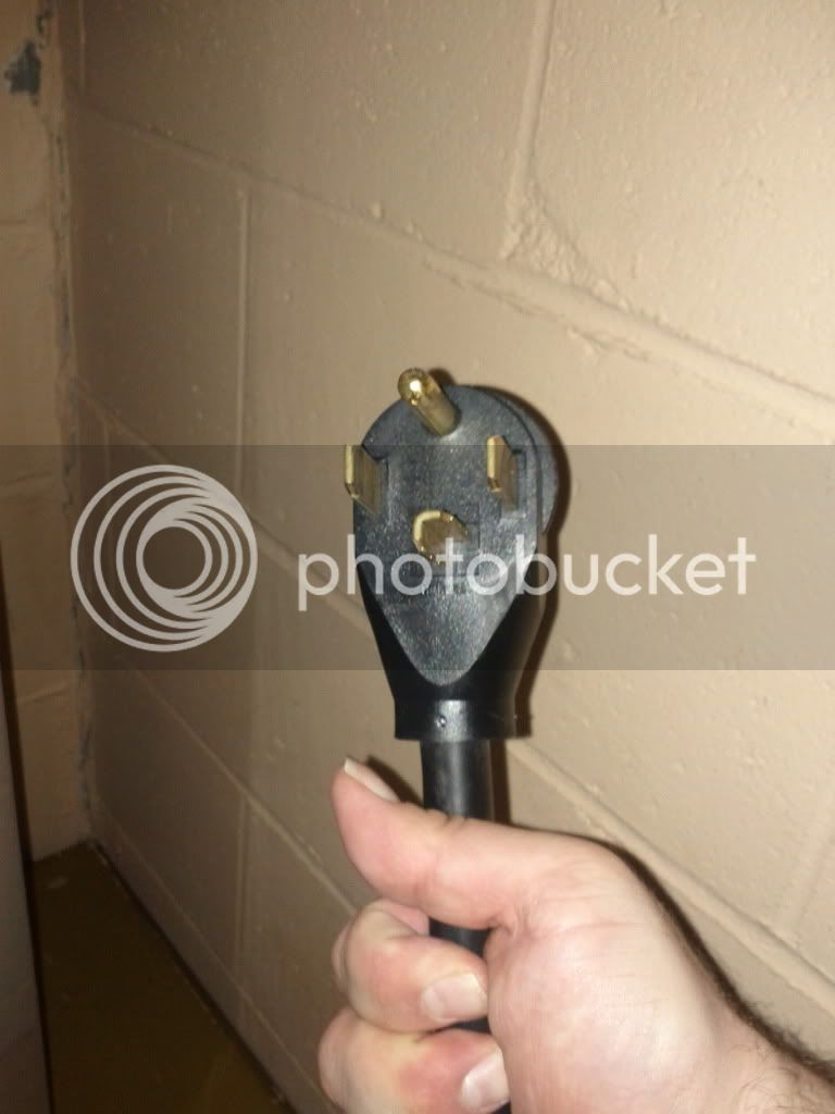
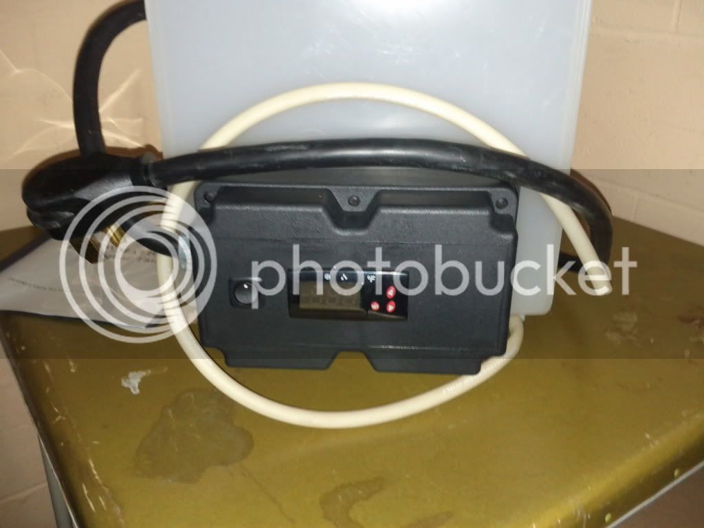
- At least 30A GFCI - however, I'd like to do simultaneous brews - To recap, my HLT instruction manual lists its' requirement as "240 VAC, Max Amperage 25A, Breaker required 30A" and, to my knowledge, it uses 2x 3000W LWD(?) elements. I intend to plug the HLT directly into the Spa Panel on one outlet, and plug my Brewery Controller in to a second outlet on the Panel (and NOT plug the HLT in to the Controller). So, more likely, I will want either a 50A or 60A Spa Panel. Need to do some "real math" to figure out what the Brewmation HLT actually needs. (I've got conflicting info on what is its' wattage.)
- I will also need to purchase two 30A 220V 4-prong female receptacles - one to plug the HLT into and one for the Controller.
- Lastly, I will need a small amount of decent gauge wire, to make the connections for both outlets, and a way to cut the hole into the enclosure. (I have a random-ass pile of short (6"-18") scraps of what looks to be heavy duty, solid core copper. They were extras from a Facilities team that did some work in our building. While cleaning up their mess for them, I decided the scraps of wire were recyclable for future projects.)
1.5) HLT - Nothing needs to be done immediately. Long-term, I plan to drill two holes, install two weldless bulkheads, and attach an In/Out for a Heat Exchanger coil within the HLT. That will come after I have a fully working system - No need to incorporate it into the Alpha version.
2) Pump Assembly
- I already have a March PL-809-HS 120V with molded cord. I would like to keep the cord intact, so I'll mount an outlet within the enclosure for this configuration. Then, if I want to take the pump with me somewhere, I can remove it from the Assembly Box, unplug it from the outlet, and away I go.
- I want to house the Assembly in a toolbox or other protective enclosure, containing both the Pump Motor/Housing, and the circuitry. (The Pump Head may stick out from one end, with the two hoses accessible, or something like that... haven't figured out the right "box" yet or how things will be positioned. )
- I want to add a DPDT(?) switch to the Pump Assembly, the switch will toggle between A) ALWAYS ON mode, B) "neutral"/Off, and C) TEMP CONTROLLER mode. When in Temp Controller mode, the pump can be used to perform recirculation of the mash through a HEX to maintain temp. or even step-mash.
- I want to add an Auber PID + SSR(?) to this enclosure. The SSR does **NOT** need to be massive, I will only be powering the March Pump with this SSR, *not any elements* so 40A/220V is not necessary. (My paperwork indicates the March Pump requires approx. 2A @ 120V.)
---When in Temp controller mode, this activates the Auber PID, and turns the pump on as-needed to maintain (or increase) the temp. of the mash.
---When in "Always On" mode, this would bypass the PID entirely.
- The Pump Assembly will also need a Temp Probe connector and a probe assembly. I am thinking an RTD type probe - and XLR 3-Pin male connector/female receptacle mounted on the enclosure to make it detachable for storage.
- The Pump Assembly should have its' own 120V cord, which will plug in to a single 120V 10A outlet on the Brewery Controller (which is protected by GFCI upstream in the Spa Panel).
- I would assume that I need to build a safety fuse somewhere into this assembly.
- One last note, the PID, SSR(?), and Mode Switch do not need to be on the Alpha version of the Pump Ass'y. It can be initially built for Always On, with sufficient room to mount & wire up the necessary parts to add the PID mode later on.
3) Electric Kettle
- I already have a spare 15gal Aluminum wide-body stock pot. I have my thin-wall Propane one, and a thick-wall one that I picked up recently second-hand. I am thinking... oddly enough... that I will use the thin-wall, propane kettle - as my electric - and build a new propane one from the thicker-wall kettle. The reason for this is that, outdoors in the cold when the wind picks up, my thin kettle acts as a giant heat-sink and strips away heat faster than my burner can keep up with it.
- One of the two kettles will get a hole drilled & a weldless bulkhead & 1/2" valve installed. (Doesn't matter which one - the other kettle already has the same bulkhead/valve - let's move on.)
- Punch the 1 1/4" hole for the Weldless Element.
- Tentative: Buy a pre-assembled element kit from TheElectricBrewery or eBrewSupply (roughly same price/quality). Mount in kettle. Done. Have a beer & congratulate self.
---Possible: Undertake making my own element assembly. (The biggest part that I do not want to deal with is the cutting/sanding/painting - NOT the electric work! I just don't have much by way of tools that cut metal in a controlled & nice-looking manner.)
- No question in my mind: I want to go with the Camco 5500W ULWD element.
- I do not need a sight glass - but maybe I'll make a stupid-simple Marker Stick to check my water level with. (It *should* work the same on both of my kettles, too!)
- No temp sensor either - If I want a "warning" to sound when I start approaching boiling, I will just use my existing "simple" stand alone thermometer/timer, and set the alarm on it for 205*F.
- Long-term, I will want to punch another hole and add a Float Switch for safety measures. This does NOT need to be in the Alpha build.
4) Brewery Controller
- I know I want this to be on the small side, NOT a giant one-panel-does-all like the Kal build. I think I would like it to be wall mounted, but that is subject to change based on the actual layout of my room and equipment once things start to come together.
- It should have a Controller Master On/Off Switch in it - that literally just disconnects & energizes the panel at the earliest point on the wiring diagram. I have read that it is a good idea to add a controller-wide safety fuse to this same area of the diagram.
- I'm okay with incorporating an eStop button + having it trigger the Spa Panel GFCI, as long as it's not too costly to add. Otherwise, I will just plan to use the Master On/Off for this purpose - and the Spa Panel will be in a physically accessible place where I can also kill power at the breaker without reaching over/past my equipment.
- It should NOT have a PID. I want to *only* control my boil kettle with this controller. After considering the benefit vs. expense, I know I want to go the PWM route - especially if I can find friend or family to solder it for me, as I have no interest in learning to solder, I am not a fine-motor-skills guy and have no intent to solder again in the future, just a one-time need.
- The PWM will pair up to an SSR of specs 220V / 40A. I have read that I also need a fuse for the SSR.
---
Note to self: Look into phase angle SSR instead of PWM circuit, to accomplish same goal.
- I want to add a Kettle Mode Switch - a DPDT(?) switch to the panel to go between "100%"/bypass PWM circuit, and "0-99%"/Enable PWM circuit. That way, when I am ramping up to boil, I can just flip it to 100% until the boil begins. Center position would be "No Contact" or for my automotively-inclined brain, "Neutral" on the shifter box.
- It should have a Kettle Element On indicator light. (Low expense, hooks up inline and doesn't add unnecessary complexity to the diagram, so I figure, "why not?")
- It should have an Kettle Intensity knob, which controls the PWM circuit when in "0-99%" mode.
- It should have one 120V 10A outlet using one of the two Hot legs - this outlet should be always-on regardless of Kettle Mode Switch position (but, still disabled by the Master ON/OFF switch).
Operation:
- When heating strike, and mashing, the Controller Master Switch will be turned On (so that the pump operates), but the Kettle Mode Switch would be in "neutral". Meanwhile, the HLT would be ON and maintaining temperature.
- When sparging, the HLT can be turned Off at the beginning of the sparge - the Controller Master Switch remains on, and the Pump Assembly continues pumping, Once sufficient wort is collected in the BK, the Kettle Control Switch would be moved to the 100% position.
- Once sparge has completed, the Pump Assembly would be turned off, and I would wait until boil began - then, immediately switch the KCS over to "0-99%" mode, and adjust the PWM Intensity Knob to a point where I maintain a boil but am not firing my element needlessly.
- At the end of boil, Pump Assembly would be turned back on, hot wort circ'ed through my CFC until sanitized, and then I would turn the KCS back to "neutral", then proceed to chill my wort as normal.
- Once chilling/collection ends, I would turn off the Controller Master Switch, which in turn shuts off the Pump Assembly. The HLT was already powered off, so at this point, I can turn the Spa Panel off entirely before I begin clean-up stage.
5) Infrastructure - The expensive and fun part - I only have 100A service - And if I plan to go 60A so that I can brew back-to-back, I will positively have to get my service drop upgraded to 200A. Oh well, It needs a new panel & service upgrade anyways. Hopefully we can do it less expensively than I think we can, and hopefully it adds enough to the house value that we're not totally screwed when we move. So, in short, new 50A or 60A service, running to the brew room, and terminating in a 4-prong 220V receptacle. The Spa Panel should be free-standing and plug into this receptacle, so that it is not permanent fixture / subject to code.
Summary
So basically, what I'm saying is, the Alpha version will only have the Spa Panel, HLT as-is, Master On/Off Switch, Kettle element/cable and receptacle, Kettle PWM Controller, and 100%/Neutral/0-99% switch, then the 120V Pump outlet, and the Alpha version of the Pump Assembly will only have the enclosure, pump, and power cord.
The Beta version will add the PID, SSR, and Mode Switch to the Pump Ass'y, and also add the HEX coil and bulkheads to the HLT.
Either during Alpha phase - or else when I enter Beta phase - I will also need to buy all of the QD's necessary for the system, and replace all of my loose/stained braided vinyl hoses with new, silicone, permanently-assembled, hose assemblies.
The Final version will add one more pump (probably just a Harbor Freight sump pump) that would give me the ability to recirc ice water for chilling instead of using my ground water - and maybe also incorporate a Float Switch in to the kettle - and perhaps a Timer + Buzzer, if I feel randy like that. But, we will get to that later on, once we have an Alpha version and glimpses of working on Beta. For now, a $12 Big Number Timer will do just fine for me - as will ground water for chilling.
WHEW! So there you have it! Thoughts. Input. Criticisms. Free beer. Whatever you've got, lay it on me.


![Craft A Brew - Safale S-04 Dry Yeast - Fermentis - English Ale Dry Yeast - For English and American Ales and Hard Apple Ciders - Ingredients for Home Brewing - Beer Making Supplies - [1 Pack]](https://m.media-amazon.com/images/I/41fVGNh6JfL._SL500_.jpg)


 whoa. to tell you the truth, I have no idea, re: the car batteries. That is far beyond the scope of my electrical know-how.