Terminal insulation question

Homebrew Talk - Beer, Wine, Mead, & Cider Brewing Discussion Forum

Help Support Homebrew Talk - Beer, Wine, Mead, & Cider Brewing Discussion Forum:

This site may earn a commission from merchant affiliate links, including eBay, Amazon, and others.

dcbw

Supporting Member
HBT Supporter
Joined
Feb 18, 2012
Messages
318
Reaction score
37
Location
Minneapolis
So I read one or two posts here about bad crimping and decided to solder all my terminals. For the most part that requires removing the insulator on the terminal since it might melt at solder temps. So here I am half done with the panel, look at some of the 240V 30A connectors, and think "Geez those are close together, and they're not insulated." How far apart should un-insulated connections like this be, especially for the main power contactor (the right-most one in the image)?

So I started shrink-tubing some of the terminals, but not the actual blades of the blade terminals. Will shrink-tubing work well enough, or should I re-do the high-voltage stuff to use fully-insulated blade connectors for the contactors? How about for the 120V stuff?

What's the required air gap for 240V 30A?

Thanks,
Dan

panel.jpg
 
Shrink tube should work just fine, I can't vouch for a required air gap, but as long as the heat shrunk terminals from different conductors (hot 1 and hot 2, neutral, etc.) are about the same distance as they are in the contactors terminal block you should be fine. The distance of the terminals on the same contuctor line shouldnt matter since they are electrically connected anyway.
 
Although I really dont like spade crimp terminals for power type connections, the clearances on your contactors are certainly within UL requirements. Bolted connections are always better. But, given solid crimped connections, with a treatment of shrink tubing you should be just fine.
 
Just make sure you crimp them as well as solder. A mechanical connection is important in the case of a 'cold' solder joint that is very high resistance. Then you are not relying solely on the solder for electrical OR mechanical joint. A high resistance connection can get hot enough to melt some solders and the wire will fall free if it wasnt crimped. Just some food for thought.
 
Just make sure you crimp them as well as solder.

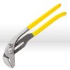
Yeah, I'm certainly crimping them as hard as I can with one of these:

klein.jpg

before I solder them. I'm using 63/37 tin/lead rosin core solder with a melting temp of like 373 degrees which I assume is good enough; the 60/40 solder at the store (which is what Kal suggests at TEB) had a melting temp of 375 so I assumed the 63/37 was good enough. I'm now shrink-tubing the spade terminals on things that are closely spaced, so hopefully that'll be good enough.

Thanks!
 
Just make sure you crimp them as well as solder.

Or, better yet, learn to properly crimp and solder, and use whichever one of those methods best fits the particular job you're trying to do. A properly-installed crimped terminal (right terminal, on the right wire, properly crimped with a crimping tool appropriate to the terminal, etc) will form a gas-tight connection to the wire, and won't need any additional help in the process. Of course, mashing down every part of the terminal with a pair of channel-locks doesn't meet those criteria. Similarly, a good solder joint won't need crimping to support it (though it may still need some sort of strain relief or insulation support, which a good crimp terminal will provide automatically).

Crimping is easier to learn to do right than soldering. Neither is difficult, but both require some instruction. If done poorly, both can fail quickly.

Were you the supplier of all the "safety fluid" on MXC?
 
I've looked on youtube and there are a few videos of how-to solder. I've soldered copper together but never wire quick disconnects. Any body know of decent tutorial on how to solder female terminal ends to the blade end of a receptacle. I have a ratching crimper tool for connection of wire to quick disconnect which is great but the connections between female quick disconnect to the blade end of the receptacle is very lose and I want to solder them for added safety.
I assume its straight forward but would feel more confident with some guided steps instead of me just winging it with a common sense approach.
 
I'd be surprised to find tutorials on soldering these pieces together, as that would completely defeat the purpose of using quick-disconnects. If you feel that it's necessary, though, I'd just use plenty of flux, a good rosin-core solder, and a hot iron. There shouldn't be anything special about soldering quick-disconnects. However, if the female terminal is loose, it'd probably be better to just replace it with one that fits snugly onto the male terminal.
 
The other, easier option - remove the copper terminal connections from the contactor, and then use the screw terminal to secure your wires. You don't have to worry about the terminal 'fingers' sticking out all over the place, and you get a nice secure connection that you can add to or adjust whenever you need.
 
the other, easier option - remove the copper terminal connections from the contactor, and then use the screw terminal to secure your wires. You don't have to worry about the terminal 'fingers' sticking out all over the place, and you get a nice secure connection that you can add to or adjust whenever you need.

+1

What kind of contactors are those?
 
Back
Top